The Locomotive Magazine and Railway Carriage
and Wagon Review
Volume 45 (1939)
key file
Number 557 (14 January)
Towards greater speed of service. 1-2
S.H. Fisher, Assistant Chief Operationg Manager of the LMSR address
to the Institute of Transport. Notes submissions to the Transport Advisory
Council from thge main line railway comapnies in the hope that some of the
regulations placed upon railways would be reduced. Noted the quest for reduced
transit times for both passengers and freight and for lighter vehicles, but
observes that passenger trains were getting heavier due to quest for greater
luxury. Pious hope that cross country transits would be eased (still further
away than ever). Proposes use of bogie freaight vehicles carrying containers
on routes such as London to Birmingham and Manchester to Glasgow. Notes
limitation of short wheelbase four wheel freight wagons and suggests
six-wheel
"The Green Howard" London & North Eastern Railway.
2. illustration
No. 4806 The Green Howard is illustrated to show the external
linkage for the multiple valve regulator header. Leading dimensions are
repeated.
The Rock Island "Rockets". 3-4. illustration
Chicago, Rock Island & Pacific Railway: Electro-Motive Corporation
locomotive with 1200hp Winton diesel two-stroke engine capable of 117 mile/h
running with Budd welded steel articulated cars with sponge rubber seating.The
cars were fitted with electric-pneumatic brakes, with a four-speed retardation
control in the leading car, and automatic slack adjusters are provided to
allow for wearing of the wheels and brake shoes. Flexible diaphragms fill
the spaces between the car bodies, giving an unbroken surface from the nose
of the locomotive to the tail of the observation car. The cars are finished
in bright stainless steel outside, while the locomotive is treated in maroon
and vermilion, with bands and lettering of stainless steel. The steel used
in the construction of the cars varies in tensile strength from 100,000 to
150,000 lb. A four-car train contains 209 seats, including 32 dining seats,
and weighs 150 tons without the locomotive unit. At present the·'
'Rockets" are in operation on five different routes, giving day services
in an cases. Runs between Chicago and Peoria and Chicago and Des Moines are
made by two four- car sets. On the three remaining services, Kansas City-Des
Moines-Minneapolis, Kansas City-Dallas, and Fort Worth-Houston, four three-car
units are employed. The Fort Worth-Houston service is worked jointly with
the Chicago-Burlington and Quincy Railroad, the Rock Island "Rocket" working
alternate runs with one of the Burlington "Zephyr" trains.
Institution of Locomotive Engineers. Wear resistance of ferrous
metals. 4-6
On 14 December Messrs. W. West and C. C. Hodgson presented a paper
on the above subject before the Institution in London.
The brief extract is on the ILocoE page
for Paper 398.
E.A. Phillipson. The steam locomotive in traffic. IV.
Locomotive depot equipment. 6-9. 2 illustrations, 3 diagrams
Wheel drops and locomotive hoists; manufactured by Ransomes &
Rapier Ltd. See also letter from C.W. Clarke on page
126
The Railway Club. 9.
P.B. Ellison talk on the Hay Railway, 1810-1863 presented in London
at the Royal Scottish Corporation Hall.
Bengal N.W. Rly. 9
Order for 6 YB metre gauge 4-6-2 locomotives placed with Vulcan
Foundry
Irish notes. 10-11. 3 illustrations
Commission to investigate Transport in Northern Ireland proposed that
the Northern Ireland Road Transport Board, the Northern Counties Committee
and Belfast & County Down Railway should merge and enter into a pooling
agreement with the Great Nortthern Railway (Ireland). The BCDR should lose
its separate identity. Transport provision in Ulster was greatly in excess
of its needs.
On the NCC No. 23 (2-4-0) and No. 31 (0-6-0) had been retained inservice,
but Nos. 51 and 57 had been scrapped making the C1 class 2-4-0 compound class
extinct. 0-6-0 Nos. 30, 43 and 44 had been scrapped. 2-4-0 Nos. 45, 46, 51
and 57 had been scrapped and class F1 became extinct
V class 0-6-0 No. 13 had received the reconditioned boiler from No. 72 and
had been painted black with the LMS crest on the cabside: the first NCC black
locomotive.
On the County Donegal Railways Joint Committee 4-6-0T Nos. 4-9; 4-4-4T Nos.
10-11 and 2-4-0T Nos. 1-3 had been scrapped and the remaining stock had been
renumbered.
Phoenix was described as a diesel tractor. It had been built as a
steamer by Atkinson-Walker for the Clogher Valley Railway in 1928 and had
been purchased by the County Donegal and fitted with a Gardner 2 L6 diesel
engine in 1932. It worked between Stranolar and Strabane with one man in
charge.
The last relics of the Dublin & Lucan Electric Railway was being lost
through road widening.
Societe des Ingenieurs Civils de France (British
Section). 11
Brief description of paper presented by O.V.S. Bulleid entitled Modern
long distance high speed trains in Great Briatin on 27 May 1938 in Paris
wherein he described the Cheltenham Flyer, Bristolian, Silver Jubilee,
Coronation and Coronation Scot and noted the problems of braking
them, but punctuality had been extremely good.
Eastern Section electrification, L.N.E.R. 11-12.
Leadhills and Wanlockhead Light Railway. 12. illustration
Closure 2 January 1939. Photograph by A.C.W. Lowe of former CR 0-4-4T
No. 15238 (with spark arrester) at Wanlockhead
Ray McBrain. The Magnaflux method of testing and inspection. 13-14. 4 illustrations
A.C.W. Lowe. The West Cornwal Railway. 15-18. 4 illustrations, 3
diagrams
Until 1852 W. Bruton was the resident engineer and his responsibilities
included locomotives. J.D. Sheriff officiated at the Carn Brea repair shops
and Slater was succeeded by H. Appleby. When the South Devon Railway took
over the locomotive stock became the responsibility of J. Wright. Three
locomotives were taken over from the Hayle Railway: Cornubia, Carn Brea and
Penzance. Coryndon was purchased from Chanter who had worked the line under
contract. A 2-2-2 with smoke eliminator was constructed at Carn Brea from
parts supplied by Stothert & Slaughter, brought by sea from Bristol to
Hayle and thence conveyed by road. It was assembled by Joseph Ramsden under
the supervision of Slater. In 1851 it was named Penzance, was changed
to Hayle in 1858 and survived until 1860 and was not cut up until
1866
D[ewhurst], P.C. L.M.S.R. locomotives: a history of the
Somerset and Dorset Joint Railway.18-20. 2 illustrations, 2 tables
Continued page 70.
Locomotives in Hyde Park, London. 20. illustration
In 1869-70 used in association with cleaning the Serpentine used by
the contrctor Jay & Co.
J.L. Koffmann. Railcar operation at high altitudes. 21-3. illustration,
2 diagrams, table.
Saurer engine with Buchi turbocharger used on Central Railway of Peru
between Oroya and Muncao and Desamparados and Caspalca.
L.M.S.R. 23.
Institution of Locomotive Engineers. 23
Some "improved" locomotive valve gears. 24-6. 4
diagrams.
Berthe gear exhibited in Paris in 1900; the Durant and Lencauchez
gears described in Locomotive Mag. in 1914 (December) and 1915 (February);
the Bonneford gear and J.T. Marshall gear as fitted to Maunsell 2-6-0
L.I. Sanders. Carriage and wagon design and construction. II Carriage and wagon underframes. 26-8. illustration, 2 diagrams.
London & North Eastern Rly. 28.
Four 2-6-0 class K engines had been completed at Darllngton, No. 3443
Cameron of Lochiel, No. 3444 Lord of the Isles, No. 3445 Mac
Cailin Mor, and No. 3446 Lord of Dunvegan.
A 300 ton wagon. 28.
The English Steel Corporation placed an order with Head, Wrightson
and Co. Ltd. for an all-steel welded wagon with a capacity of 300 tons with
a length of 60 ft. over buffers and carried on four six-wheeled articulated
bogies.
L.M.S.R. 28
New power driven turntables to be installed at the following
depots:-Plodder Lane (Bolton), Widnes, Keswick, Wellingborough, Sheffield
(Grimesthorpe), Peterborough, Toton (Derbyshire), Evesham, Leicester, and
Liverpool (Exchange). Eight of the new turntables to be of larger diameter
than those which they replace, in order to accommodate bigger
locomotives.
Great Western Railway. 28
The following engines had been completed at Swindon and were in service:
Nos. 3220 and 3221 (4-4-0 passenger engines); Nos. 2894 to 2898 (2-8-0 mineral
engines); No. 7249 (2-8-2T), No. 8103 (2-6-2T) and Nos. 3795 and 3796 (0-6-0T).
The following had been withdrawn: No. 880 (0-6-0 goods, ex Cambrian No. 77);
Nos. 1220, 1641, 1765, 1806 and 1947 (0-6-0T); No. 3181 (2-6-2T), No. 4371
(2-6-0), and No. 4068 Llanthony Albbey (4-6-0).
Reviews. 28
The history of the Highland Railway. H.A.
Vallance. London: Arthur H. Stockwell, Limited.
Various factors have gone to make the old Highland Railway a favourite
with those who love railways for their own sake. The beauty of the country
it served had something to do with this, but perhaps even more compelling
was the way this small company carried on traffic over long distances, in
the face of Nature at her unkindest, and with a banking account that was
never very fat. As might be expected, Vallance's book is a quite unofficial
labour of love, and for it. he deserves congratulations, more, indeed, than
those who have been responsible for the book's production. He has certainly
made a very good job of it. There are seventeen chapters, covering the whole
of the Highlandts history, beginning with Joseph Mitchell's earliest proposals
for an Inverness to Perth direct railway, which was born in the Railway Mania
of 1845. One may quarrel with a few of the author's non-railway references.
It is hardly fair on General Wade, for instance, to wr i te that in building
his famous roads he "only considered the military aspect of the undertaking"
for Wade was a far-seeing and humane man who certainly did not have
"pacification" as his sole object. On the opposite side, the memory of nineteenth
century landowners in the Highlands, who were the Highland's principal sponsors,
is somewhat buttered up, though it should scarcely be implied that the
"improvements" (forced evictions) ceased with the coming of railway transport.
Vallance's capacity as a railway historian is undoubted, and his account
of the gradual formation of the ultimate H.R system, the quarrels with the
Great North of Scotland, and especially of its unfulfilled aspirations, is
most valuable. The Great Norrh adopted the role of an interfering rich uncle,
though by that time was anything but rich. An excellent chapter, too, is
devoted to the difficulties of single line working, and in this occurs the
authentic story of the Englishman who took two days to travel from Inverness
to Perth. Special chapters are also devoted to the train services, the H.R.'s
unenviable role in the Great War, accidents and fighting the "Snow Fiend,"
as well as a complete chapter on the company's little-known steamships.
Though detailed accounts of performance, rebuilding, and working are necessarily
precluded, the section devoted to Highland locomotives is comprehensive and
reliable, the fortunes of even the obscurest Highland engines being faithfully
followed. Very welcome, too, is the material, much of it hitherto unknown
to the general reader, relating to the Carriage Department, and particularly
to the early sleeping cars. But the reviewer is a little surprised at an
historian of . Vallarices calibre referring to Alexander Allen, and to Sir
John Rarnsbottom.
The illustrations are numerous and well chosen, but they suffer from poor
printing. There are several most interesting maps, showing the system as
it was, the system al Mitchell conceived it in 1845, and various suggested
scheme in the remoter Highlands and in the Inner and Oute Hebrides. On the
whole, Vallnce has given us a valuable book, which those who know the old
Highland will undoubtedly welcome.
British light railways. R.W. Kidner. London:
Oakwood Press. 28-9
In his preface to this work the author refers to travel on light railways
as a mode "which was sometimes useful, too often merely comic, but nevertheless
an important part of thl history of transport." Most of our readers will
agree with this, and in view of the number of these concerns which have ceased
to function during recent years, will be glad of a record of their scope
and activities. The railways, over sixty in number, are dealt with in six
groups, and for each there is a diagram of lines and stations, showing locomotive
sheds and sidings with the distances of the principal stations, Dates of
opening and closing, together with a list of locomotives and some details
of coaches, track, signalling, livery and tickets, are also appended. The
whole of the British Isles is covered by the work, which is illustrated by
91 excellent half tone blocks, these forming a useful record of the locomotives
and scenery of the various lines. It is, however, much to be regretted that
the small locomotive sketches, which number 204, have been so crudely
drawn.
Old Euston. G. Royde Smith. London: Country
Life Limited, for the London, Midland and Scottish Railway. 70 pp. plus 6
plates. 29
The book produced by that well-known authority on early railway history,
the assistant secretary of the L.M.S.R., in accordance with the desires of
the L.M.S.R. directors to have a brief retrospect coincident with the centenary
celebrations of the London and Birmingham Railway, the first of England's
main line routes, is not only accurate and balanced without being tedious
or compendious, but is also delightful to read. The title is symbolic of
the importance of Euston to the L. & B.R., and to the L.N.W.R. and L.M.S.R.
in after years, and the contents are a resume of the human essentials of
the first thirteen years of more than a century of activity rather than an
account of the London terminus itself, the history of which can be summed
up in one sentence of Mr. Royde Smith's: Nobody remembers the time when Euston
Station was not being altered or added to in one way or another." First there
are chapters on the origin of the London and Birmingham Railway itself, on
the Euston extension line, the Hardwick arch and the Central Hall, and on
the increase of traffic. Then comes an almost impartial but friendly chapter
on Edward Bury and his locomotives, which everybody should welcome, for there
has been a fashion to decry him. It was no joke being a responsible engineer
on the L & B.R. in the early days, for the Quaker directors, Cropper
and Rathbone, not only made Bury's life unpleasant, but, as Robert Stephenson
recorded in a lenter to Michael Longridge dated 26 January 1835, they were
in hue and cry after their civil engineer, too. Then again, it appears that
some of the directors did not consider themselves there simply to direct,
but to interfere in the management.
There must be some regret that Mr. Royde Smith has not spent just another
dozen lines on the Harvey Combe, Stephenson's pa:tent engine of 1835.
According to Warren, in A Century of Locomotive Building, it is this
engine which is described in Marshall's Description of the Patent Locornotire
Steam Engine of Robert Stephenson and Co., 1838, but Ahrons states that
it is a somewhat later engine of the same type which is described in Tredgold's
Steam Engine. The present records state that it was built for Belgium
and sold to Cubitt, who was contractor for the London and Birmingham line,
but Warren states simply (p. 320) that it was built [or Cubitt. The drawing
in Mr. Royde Smith's book agrees with that given by Warren (which was taken
from Marshalls work) except the positions of the dome and manhole.
Engineering workshop principles and practice. A.G, Robson.
Manchester: Emmott & Co. Ltd., 29
The importance of this book to a student should be in almost direct
relation to the time in his apprenticeship when he begins to study. If it
should not come into his hands for six months Or a year after he has begun
to serve his time, the undoubted value of the first half-dozen or so chapters
will be lost upon him, for he will have already formed several bad habits
which no amount of correct instruction will wholly break off. As the L.C.C.
has adopted this work as a textbook, there is a chanoe here, at least, that
the full value of the book will be extracted, In 32 chapters an amazing amount
of general engineering and machine tool practice is covered, and covered
well, for the text and illustrations give an apprentice just that what he
needs to know about the tools and machines which he is to use and about others
around him, although possibly it is asking a little too much of
student-apprentices to expect them to appreciate the chapters on gauge-making,
heat treat- ment of steel, and the manufacture and properties of metals.
In its technical aspects the book is quite up-to-date, and is singularly
free from those examples of Victorian engineering practice which are a
characteristic of many works which originated in pre-war years.
Correspondence. 29-30
Edward Fletcher. J.W,A..
Re correspondence on Fletcher .boilers, and a cutting I have from
The Engineer 30 June 1882, sheds some light on the weakness of Fletcher's
boilers. Colonel Yolland, reporting on an accident to engine No. 204, class
398 (standard 0-6-0), which blew up at Thornaby on 26 December 1881, says
"that the accident was probably caused by the crown of the firebox becoming
overheated from want of water, and thus weakened, having been unable to resist
the pressure caused by the sudden creation of steam upon water being admitted
to the boiler. "
The boiler was only in use 21 months, and the copper firebox and stays were
in good condition, and it was unknown whether the one water gauge was faulty
or the driver had been careless, but he states that it is most desirable
that duplicate gauges be fitted to all boilers. The main point of his findings,
however, is that the difference of level between the top of the boiler and
the crown of the firebox was only 13 in., which was small in the case of
this engine, and would, of course, allow the firebox crown to become uncovered
very quickly, without constant attention. He was not aware of the greatest
difference in levels then existing, but some engineers kept down the firebox
crown 20 in. below the top of the boiler, and 15 in.-18 in. was a common
difference of level. The lead plug (which failed to give way) was found to
have been covered over with a hard incrustation at the bottom of the lead.
This had not been removed for four or five months, there being no regular
time for renewal at that period. The above may throw some light on the Fletcher
boiler weakness.
Incidentally, the five men killed in the explosion were buried in the North
Cemetery, Darlington, and photographs of four of them are mounted in lead
frames round the memorial erected to their memory.
Edward Fletcher. C. Hamilton
Ellis.
Further to W.B. Thompson's comments on the liability of Fletcher's
North Eastern locomotives to boiler explosion, the following extract from
the official report on the Silksworth accident of January 1880 may be of
interest: "From a careful examination of the surfaces of fracture there is
but little doubt that the explosion commenced on the left hand side along
.the junction of plates 1 and 4, where there is deep grooving in the lower
plate, in some instances extending through almost its entire thickness in
a line along the bottom of the overlapping portion of the upper plate. This
grooving would have been hardly discoverable (even had it then existed) when
the inside of the Iboiler was examined at the end of 1878, as it was to a
certain extent covered by the overlapping edge of the upper plate. This grooving
was no doubt more or less due to the proximity of the joint to the plate
attached to the side of the firebox, which rests on another plate attached
to the framing to permit of the expansion and contraction of the boiler.
The bearing surface being considerable, a great deal of resistance is offered
to free expansion and contraction, and much work, giving rise to grooving,
consequently takes place in the joint in question."
Robert Sinclair. G.G.
Woodcock.
Re article upon R. Sinclair in the Locomotive of November issue. Your
contributor might have mentioned that Sinclair with Allan was one of the
first to introduce long laps and valve travel as we know it to-day. Probably
owing to the haphazard lubrication systems in use at the time, he as quickly
dropped it. By the way, it is interesting to note that although Gooch had
commenced construction of locomotives at Stratford, the first being his 2-2-2
tanks 1851-54, Sinclair never constructed any there except five small 2-4-0
side tanks for the Woolwich branch.
The Webb compounds. C. Williams. 30
Re the letters by W.B. Thompson and
W.T.H. on page 402 of the December issue
The first three Teutonic class compounds were built with experimental low
pressure cylinders of different sizes, and just prior to the buiiding of
the seven remaining engines of the class in 1890, Webb decided to adopt the
30 in. as standard. Consequently Teutonic retained the original l.p.
diameter. whilst those of the Oceanic and Pacific were both
modified to the new standard in ]890. Although not previously recorded, it
may be of interest to note that a number of the Dreadnoughts were subsequently
fitted with h.p. cylinders 15 in. in diameter, including No. 545
Tamerlane which also had the l.p. cylinder reduced to 28 in. in diameter.
As regards the 0-8-0 three-cylinder compound No. 1880, I well remember seeing
this engine in 1900 both before and after it was converted (the date 1903
for the latter is incorrect). Originally it had a large cylindrical (not
Belpaire) firebox with a corresponding large boiler, and was so built, I
believe, as an experiment. I regret that I am not able to furnish any details
of the firebox in question.
Metropolitan Vickers Electrical Co., Ltd. 30
Railway Traction Work during 1938. Work on the electrification of
the Central Railway of Brazil has continued satisfactorily throughout the
year, the sections being open for traffic progressively as completed. The
first order for 52 Metadyne Control Train Units from the London Passenger
Transport Board had been followed by two further orders totalling a further
73 equipments. The order from the South African Railways for a further 42
electric locomotives received in 1937 has been completed. Twenty-seven of
these locomotives were despatched before 31 October, and a further ten during
November and December. The total number of locomotives ordered by the South
African Railways was 162.
An important order had been received from the London and North Eastern Railway
for the complete electrical equipments for 70 main line mixed traffic locomotives
in connection with the electrification of the Manchesterv Sheffield-Wath
lines. Work on these equipments was well advanced and deliveries would commence
during 1939. The mechanical parts will be manufactured by the London and
North Eastern Rly. at their Doncaster Works, where the Metropolitan- Vickers
Company will erect the electrical equipment and complete the locomotives.
The locomotives will weigh about 84 tons each and run on 1,500 volts D C.
They are equipped with 4-axle mounted motors having a total one-hour rating
of 1,850 h.p. and designed to draw 250 ton passenger trains up a gradient
of 1 in 125 at 53 m.p.h., 500 ton express goods trains up a similar gradient
at 40 m.p.h., or 700 ton goods trains up a similar grade at 26 m.p.h. The
maximum speed is to be 65 m.p.h. The locomotives are to be equipped for
regenerative working, which will be a very valuable feature in handling the
heavy freight rrains down the long grades in the Pennines. An additional
24 motor coach equipments for the suburban electrification near Sydney,
Australia. had been ordered by the New South Wales Government Railways, The
motors were being made by the Australian General Electric Company to
Metropolitan-Vickers design, and parts of the control apparatus were being
manufactured at Trafford Park.
Trade Notes and Publications. 30
The Butterley Company, Limited, 30
Butterley Iron Works, near Derby, have orders for the steelwork for
a bridge carrying Wilford Road, Nottingharn, over the L.M.S.R., main line.
The bridge has five spans and an angle of skew of approximately 45 deg. The
old ironwork to be demolished weighs 350 tons, and the weight of the new
steel structure will be 230 tons. The Butterley Company have also secured
the contract for approximately 1,200 tons of steelwork in five bridges in
connection with the widening and electrification of approximately two miles
of track for the G.W.R. at Ruislip.
General Electric Co., Ltd. 30
The opening of an extensive addition tothe Southampton Works of
Pirelli-General Cable Works, Ltd., an associate of the G.E.C., marks an important
stage in the development of this Company's manufacturing resources. Originally,
all types of Pirelli-General cables were made at Southampton, but in 1928
the increasing demand for power cable and super-tension ca-ble led to the
erection of a new factory at Eastleigh, where paper insulated cables (including
the super-tension oil-filled type) and telephone cables are produced. Additional
space was thus made available at Southampton for the manufacture of
rubber-insulated cable, flexible cords and covered wires for winding and
instrument work, and in the last few years the factory has been successively
enlarged, attaining a covered 'area of 350,000 sq. ft. at the end of last
year. Recently, however, the still increasing demand made a new extension
of 80,000 sq. ft. necessary, bringing the total area of factory under cover
to about 425,000 sq. ft.
[ R. C. Giggins]. 30
An appointment in the G.E.C. is that of R.C. Giggins to the administrative
staff of its Government and Railways Department. The activities of this
department have increased ver y considerably during the past few years, and
present conditions have made it busier than ever before. Giggins has been
with the G.E.C. for 24 years. Since 1929 he has been General Manager of the
Company's organisation in Malaya, where he was one of the pioneers of-and
later Chairman of-the British Malaya Broadcasting Corporation.
Report on Economic and Commercial Conditions in Portugal,
by A. H. W. King, O.B.E. 30
Issued by His Majesty's Stationery Office references are made to the
deterioration of the financial position of the Portuguese Railways due to
road competition and increase in cost of coal and other materials. The average
price paid for coal in 1936 was 18s. 11d. per ton, which rose to 27s. 3d.
per ton in 1938. At the end of 1936, 2,768 km. of broad gauge and 723 km.
of narrow gauge railway were being operated. The rolling stock consisted
of 526 steam locomotives, 22 electric motors, 1,298 passenger carriages,
and 9,601 wagons, of which 1,138 were privately owned.
RapieR-Fairmont Rail Motor Cars
Title of a leaflet received from Ransomes & Rapier. Types of
inspection and gang trolleys are illustrated.
Bassett Lowke Ltd. of Northampton. 30
New catalogue of Gauge 0 scale Model Railways. It is very complete
and most attractively produced. There are eleven sections covering locomotives
— clockwork, electric and steam; rolling S10ck, passenger
and goods stations, tunnel mouths, signal cabins and accessories of all
kinds.
Number 558 (15 February1939)
Cast steel frames. 31.
The cast steel frame began to displace the forged bar frame in American
locomotive practice about 1908. The reasons for this and previous changes
may be briefly reviewed as illustrating the progress made in frame construction
in that country.
The bar frame was originally introduced in the United States because no
facilities existed for producing plates suitable for frames, whereas a smith
of average skill was capable of forging a frame from bars. This frame never
could lay claim to simplicity but was found in practice to possess certain
advantages although expensive to make and repair.
The forged frame was displaced by the cast steel frame which in its original
form consisted of cast steel side members, generally resembling the forged
members they succeeded, independent cylinders, cross-ties, etc., being retained.
At this juncture, 'it is of interest to note that where separate sides are
still utilised the bar frame is sometimes produced by flame cutting from
a solid steel slab; in this process the slab after straightening' is heated
to between 400°F. and 600°F. and held at this temperature
during the cutting process, being afterwards normalised. The present development
of the cast steel frame has resulted from much research and may fairly be
claimed to ha ve radically affected locomotive design, and as a corollary
construction and maintenance. This type of frame is usually referred to as
a "bed" and may vary between the compara- tively simple one-piece steel casting,
comprising the sides and cross braces, as introduced in 1924, to the modern
bed consisting of sides, cross braces, cylinders, back cylinder covers, inside
steam pipes, smokebox saddle, sundry brackets, brake hangers, etc., constituting
one of the most elabo- rate steel castings ever manufactured. At first sight
it may appear that excessive weight must be associated with this form of
construction, but this is not the case as the metal may be propor- tioned
subject to the stresses involved-a procedure largely impracticable with the
bar or plate frame. The obvious advantages are reduced maintenance and greater
freedom in design.
There are many comparatively modern locomo- tives at work to-day which are
in frequent need of frame repairs and alignment, cylinders tightening,
etc.-troubles which cannot arise with the cast bed.
That the claim for reduced maintenance is amply substantiated would appear
from the fact that railways in some countries are prepared to import these
beds, although the cost is considerably increased by duties.
In addition to this type of construction being used on some of the largest
steam locomotives, e.g., the Baltimore and Ohio 4-4-4-4 engines, (the bed
of which has four integral cylinders), and the Southern Pacific 4-8-8-2
articulated locomotives (having a bed for each unit), the one-piece cast
bed is also utilised for Electric and Diesel locomotives. Representative
of the former are those incorporated in the Pennsylvania Class GG-1 electric
passenger locomotives, while some of the latter have the fuel-oil and water
tanks cast integral. The type of construction under review is definitely
established and one firm alone has sup- plied upwards of 1,650 cast beds
to some 40 rail- ways operating on the American and Australian Continents;
further, the use of these is by no means confined to new construction as
they have been applied to literally hundreds of rebuilt engmes. .
So far locomotive builders in this Country, while no doubt generally interested
in these frames, have refrained from incorporating them or producing them,
but the time has come when the production facilities must be reviewed.
Fashions in locomotive practice may not change frequently, but when change
is decided upon it is usually and necessarily sudden. As an example we may
cite the etherlands Railways; for many years Holland was looked upon as a
stronghold of British practice and plate frames were as a consequence used,
but when new locomotives were supplied in 1929 bar frames made their appearance.
It is probable that an enquiry from an overseas market may before long contain
a stipulation that a cast bed must be incorporated.
While locomotive builders need not necessarily produce such units
themselves—and in America many are produced and machined
by steel founders and supplied to builders-it would, we think, be opportune
to ascertain, and if necessary assure, that facilities are available here
for the production of such castings. It would also be advantageous to look
over machine-shop equipment, as although the machining required is far less
than on a frame assembled from components, the setting-up and machining of
such a large casting obviously presents problems to shops hitherto dealing
only with the smaller components. of plate or bar frames.
South African Railways, new Beyer-Garratt locomotives. 32-3. illustration.
Part of an extensive replacement programme, sixteen Beyer-Garratt
locomotives with the 4-8-2 + 2-8-4 wheel arrangement had been supplied by
Beyer, Peacock and Co. Ltd. of Manchester. Among many features was the provision
of an auxiliary water tank (not shown in illustration). This was necessary
in order to keep the max. axle weight down to 15 tons; even this is a higher
loading than normally permissible and was conceded conditionally on the weight
usually placed on the bogies being reduced, together with a restriction in
reciprocating balance. These engines were believed to be the most powerful
ever placed on 60 lb. rails and were intended to work on the
Johannesburg-Zeerust-Mafeking line; with long grades as steep as 1 in 40
in addition to curves as sharp as 477 ft. radius. The comparatively large
wheel diameter of 4 ft. 6 in. was decided upon with a view to reducing
maintenance costs and to permit of the use of these locomotives on passenger
trains. For an engine of 3 ft. 6 in. gauge the boiler was of exceptional
size, but despite this the centre is only 8 ft. 6 in. above rail level. Although
a new type, these engines contain many details and parts interchangeable
with those of other recent classes. A smart appearance has resulted from
leaving the planished steel covering of the boiler unpainted and the use
of stainless steel crinoline bands, hand rails and cylinder covers. On test
these engines have handled trains of 750 tons, and it is anticipated that
their use will increase the capacity of the line by approximately 50 per
cent.
Departure of the "Coronation Scot" to America. 33
The M.S. Belpamela left Southampton Docks on Thursday, 26 Jan..
Two special trains, one composed of the engine and the 'Other of the coaches,
made a midnighrt: journey from Willesden Junction direct to Southampton Docks,
arriving there in the early hours of January 19. The engine did not travel
under her own steam, but was hauled dead with connecting-rods and other gear
packed up securely for the 2,000 miles sea journey. The coaches, covered
with a coating of wax to protect them from exposure, and a1l movable fitments
securely lashed, formed a separate train. The engine and tender were lifted
by the ship's derricks into .the hold, and the coaches, lashed and screw-coupled,
were carried on deck. The Belpamela was expected to reach Baltimore,
her port of entry into the United States, on or about 14 Feb. Immediately
on arrival the train will be assembled at the Baltimore shops of the Baltimore
and Ohio Railroad and, after a trial run, will start on her 3,121 miles American
tour prior to exhibition at the World's Fair, New York.
Correction.- 33
It was stated in our Irish Notes last month that the proposed capital
of the new Northern Ireland Transport Merger was the sum of four million
pounds. This figure, however, only refers to the existing capital liabilities
of the Northern Ireland Road Transport Board, and the capital of the new
body will be considerably greater.
Institution of Locomotive Engineers. Diesel train with multiple
axle drives. 33-4.
Resume of paper by Haworth and
Horbuckle Paper No. 400: reproduced thereat
L.M.S.R. 34
Additional 2-8-0 standard freight engines (Class 8) recently turned
out at Crewe were Nos. 8098-8103. Of this series the first five engines,
Nos. 8096-8100, had been allocated to the Midland division. The series of
twenty 4-6-0 mixed traffic engines recently completed at Crewe were now all
in service in the Northern division, Nos. 5452-5471 inclusive. The first
ten went to the Highland section, whilst two of the others, Nos. 5469 and,
5470, were at Edinburgh. No. 5515 of the three-cylinder 4-6-0 Patriot class
had been named Caernarvon. The following ex L.N.W. G1 class 0-8-0s
had been converted to class G2 and had the power classification raised from
6 to 7: -Nos. 8905, 9114, 9281, and 9392. These engines were fitted with
standard Belpaire boilers. Recent withdrawals on the Western Division include
the following ex-L. N. W. engines :-4-4-0 Nos. 25322 F. S. P.
Wolferstan, 25357 Bassethound (George V class) ; 4-6-0 Nos. 25756,
25802 (Prince of Wales class); 4-4-2 Tank Nos. 6806, 6826. One of the ex-C.R.
Pugs was at Crewe to await scrapping, No. 16004. The latest 2-6-4 passenger
tank ex Derby was No. 2652. Recent withdrawals included ex-M.R. 2-4-0s Nos.
20092, 20238, 20267; and 0-4-4 tanks Nos. 1228 and 1392.
"The Coronation Scot" [for the] New York World's Fair, 1939. 35-9.
7 illustrations, plan.
L.M.S. train destined for exhibition at the New York World's Fair
was shipped to Baltimore from Southampton on 26 January 1939. Prior to going
to the World's Fair the complete train with locomotive No. 6220 Coronation
would visit several American cities. No. 6220 had been specially fitted
with a bell and searchlight, shown in the photograph.
The train is a portion of that under construction at the Derby Works of the
L.M.S. Railway for service in Great Britain, and consists of three articulated
twin sets and two loose cars, made up as follows:-
Corridor 1st Brake, Corridor 1st Class: Articulated Twin Set (16 and 24 seats):
40 seats. Corridor 1st Lounge, 1st Class Dining Car, Articulated Twin Set
(28 and 44 seats): 72 seats.
Kitchen Car, 3rd Class Dining Car, Articulated Twin Set: 44 seats.
1st Class Sleeping Car, Separate Car: 12 berths. Club Saloon, Separate Car:
17 seats.
Totals: 173 seats and 12 berths.
The exterior painting is in the standard L.M.S. colours, with four gold bands
running the full length of the train, continuing round the shaped ends of
the brake compartments at each end, and finishing in a "V" shaped point in
the centre. These bands also appear on the engine.
Exterior projections have been reduced to a minimum, the roof, sides 2nd
ends being covered with 16 S.W.G. steel panels finishing flush with the windows,
and between the bogies is a sheet metal valance to within 12 in. of the rail
level.
To preserve continuity of line, the spaces between the adjoining ends of
each pair of vehicles are closed with rubber sheeting, the exterior thus
presents a smooth uniform appearance over the whole length of the train.
The body side doors are fitted with "Beclawat" spring balanced frameless
drop lights.
Special attention has been paid to sound insulation. The corrugated steel
floor sheets are welded to the steel underframes, and the underside sprayed
with " Limpet" asbestos 3/8 in. thick, the flooring consists
of cork 1 5/16 in. thick on which is laid felt, linoleum,
and carpet.
The inside of the roof, bodyside and end panels and framework are sprayed
with "Limpet" asbestos, whilst the walls and partitions of the dining cars
and lounge car are lined with leather on a felt foundation.
The body sides are also fitted with twin glass windows having an air space
of ¼in. between in order to insulate against heat and sound.
The design of the body and underframe is arranged so that the solebars and
cant rails are combined as one unit and the trussed longitudinal members
another.
Solebars and cant rails are of Colville's high tensile steel channel section
and welded to these are steel sockets to receive the teak body pillars, which
are bolted in position to the sockets. Between the quarter light pillars,
the body frame is reinforced by steel diaphragms, which have steel angles,
spot welded along each vertical edge. These diaphragms are welded to the
solebar, cant rail and sockets, and attached to the timber pillars by bolts
passing through the angles on the diaphragms.
The steel body panels (16 S. W. G .) are welded throughout in one unit extending
between each pair of bodyside doors and secured in position by screwing to
the timber framing and welding to the cant rail at the top. The galvanised
steel roof panels are welded in position to the roof members which are of
light construction, the latter being secured to the cant rail by welding.
The bodyside framework is ventilated throughout by introducing an air stream
through grooves provided at regular intervals of 6 in. between the bottom
edge of the bodyside steel panels and the timber securing fillets attached
to the solebars. The steel roof panels are also arranged with the bottom
edge clear of the bodyside panels, thus providing an air space along the
whole length of the car.
Complete circulation of air is effected by providing ventilation holes in
suitable positions in the bodyside framing, cant rails and roof members.
Exterior ventilators are fitted, evenly spaced, along the centre of the roof.
All underframe members, with the exception of the solebars, are of mild steel
and welded throughout. At one end of each articulated underframe is fitted
the standard draw and buffing gear, and at the other the Gresley type of
articulation coupling.
The bogies are constructed of mild steel, welded throughout and have laminated
springs, following the design of those fitted on existing L.M.S. articulated
stock.
The interior decoration of the corridor compartments is carried out on modern
lines, a flush finish being obtained by the use of veneered panels. A variety
of selected Empire timbers are used, each compartment being finished differently.
The corners of each compartment above the seats are rounded, with a cove
veneered to match the panels, thus giving an unbroken line to the finish.
The seats are deep sprung with loose cushions. Dunlopillo armrests and head
rests are upholstered in uncut moquette, self- coloured except for vertical
lines in the blending colours. Three colour schemes are introduced, blue
grey, brown and plum, the curtains and carpets toning with each of the schemes.
A telephone is fitted below each window for communication with the attendant
in the kitchen car, and each passenger is provided with an electric cigar
lighter.
The corridors are flush finished in figured teak, with sycamore inlaid banding,
and walnut plinth.
The lavatory finish is in blue rexine, with rounded corners and ivory ceiling,
porcelain pedestal wash basin, lavatory hopper and toilet shelf are coloured
to tone with the walls. Blue and white Terazzo mosaic is used for the floor
which is fitted with a deep cove to facilitate cleaning. Hot and cold water
is provided and a "Dixie" cup drinking machine with water filter is fitted.
The windows in these compartments are circular, the top half being hinged
for use as a ventilator. The usual outside semaphores are not fitted in
connection with the passenger communication apparatus, but an indicator is
placed in the vestibules above the outside doors, which in its normal running
position, shows a white disc behind a glass panel. When the apparatus has
been operated a red disc appears, and it can be returned to normal by the
guard with a few turns of a key, bringing the white disc in view again and
at the same time allowing the valve to be reseated in the passenger communication
valve box, situated on the end of the car. The latter is connected to the
vacuum brake train pipe as is the standard practice. The interior of the
Club saloon is finished in brown oak, with ivory enamelled ceiling. The body
side and partition panels are relieved by a triple twist rope moulding. Chairs
and settees upholstered in coral leather are arranged in groups as will be
noted by the illustrations. The floor is covered with a nigger brown fitted
carpet, divided into squares by red lines. The curtains are in colours to
tone with the furnishings.
An electric glow fire is also fitted in the centre of the cross partition
at the opposite end of the saloon to the brake compartment, and with a settee
and easy chairs suitably arranged gives a fireside effect to this end of
the car.
In the interior decoration of the 1st and 3rd class dining saloons, a novel
effect has been obtained by lining the walls and partitions with leather
on a felt foundation. The seats are also upholstered in leather with loose
cushions, the double seats being designed to give the passengers individual
seating, the seat ends are also covered with leather and supported on metal
legs. All fittings are finished in silver plated satin, and the metal cornice
mould has a leather insert coloured to tone with the walls of the saloon.
The colour scheme for the 1st class dining saloon is grey for the walls and
seat ends with dull pink seats and back, the sliding doors being faced with
Bakelite to match the walls. The third class dining saloon has green walls
and seat ends with brown for the seats and backs, and doors finished with
Bakelite panels.
The ceilings in both saloons are panelled in 3-ply with ivory enamelled finish.
The fitted carpets and curtains are in colours to tone with the respective
colour schemes. The seats are arranged two on one side of the gangway, and
one on the other side, except at the doorways, where double seats have been
eliminated in favour of a group of single seats. This arrangement provides
ample space for the movement of passengers and attendants, and avoids disturbing
diners in the vicinity of the doorways.
The interior decoration and arrangement of the cocktail lounge is distinctive,
and introduces some new features. The walls do not follow the contour of
the body side but are built out from the cant rail, providing a flat vertical
side with wide window sills. The ventilating and heating duct is housed behind
the boclyside panels, and an alcove electric light fitted between each pair
of windows extending the full depth of the latter. The curtains are so arranged
as to hang back clear of the window span when not in use, giving the passengers
full advantage of the large observation windows.
The walls and partitions are covered with blue leather as also is a portion
of the ceiling across the car adjacent to the partitions, leaving a ceiling
panel of ivory finish, down the centre of which runs a specially designed
electric light fitting. The doors and sills are finished in blue. The walls
and partitions are panelled out with chromium plated mouldings, and as in
the case of the dining cars, the leather is mounted on felt. The colour scheme
of the compartment is red, white and blue, the tables and fixed swivel chairs
being upholstered in blue. The blue carpet is divided into squares by red
lines; red and white are also introduced in the design of the curtains and
table tops.
The cocktail bar recess has a flat ceiling with a dome. The walls adjoining
the bar are covered with cream Wareite with interesting mural designs. The
counter top is veneered with red Bakelite, and stainless steel edgings. The
front of the bar is padded with Dunlopillo rubber, covered with blue leather
and divided horizontally into three sections, with white leather covered
beads, and :finished with a stainless steel skirting. Three revolving stools
uphol- stered in red leather and having chromium plated tubular standards
are spaced round the bar. The back of the bar is fitted out for service.
A sink is provided with hot and cold water, the former being supplied from
a boiler situated in the under frame below.
The sleeping car was built in 1936 and has been withdrawn from traffic to
accompany the train to America. It has a welded steel underframe and six-wheeled
bogies, of the standardL.M.S. design for this class of stock. The body framing
consists of timber pillars secured by steel sockets which are welded to the
underframe and steel angle cantrail. The body sides, ends, and roof, are
covered with 16 S.W.G. steel panels, the latter being welded to steel angle
roofsticks.
Twelve berths, lavatory and attendants' compartment are provided, and from
the latter, light refreshments and hot beverages can be served. The corridor
is finished in walnut and sycamore. The walls of the berths are covered with
blue green shaded material, and the bedspreads and carpets are to tone. The
wash basin is pale yellow porcelain, with hot and cold water taps.
Ventilation and heating are effected by a Thermotank equipment. The ventilating
unit is housed above the vestibule ceiling and, through separate ducts supplies
heated air and air at atmos- pheric temperature to a punkah louvre in each
sleeping berth. The air is cleaned by filters of the viscous type. Ceiling,
mirror and bed lights are provided, the latter having dimming facilities.
The kitchen car has new features including a solid fuel burning cooking range.
Smokeless fuel is fed by gravity on to a special form of grate which combines
the functions of preheating and the first stage of combustion. The first
part of the grate is inclined, and this forms the preheating zone; there,
the fuel is brought to ignition temperature before any air is admitted, by
radiation from the refractory walls of the firepot. The combustion zone is
the horizontal part of the grate, which is fitted with an ash ejector. The
fuel-bed works as a semi-producer, and it is thick enough to ensure that
the gases leaving the fire-pot contain a high proportion of combustibles.
Secondary combustion is obtained by preheated air introduced into the flue
of the oven. The hot gases are burnt by this secondary air with a re- versed
flame, and so they are raised to a temperature that permits very high rates
of heat transfer both to the hotplate and to the griller. The latter is a
patented device developed on behalf of the British Coal Utilisation Research
Association by Professor Rosin, which grills very efficiently without an
exposed fire. The essential feature of the Rosin grill is a refractory brick
dividing the gas stream and transmitting a controlled portion of the heat
to the grilling surface by re-radiation. The cooker proper is of normal type,
and is designed to give all the facilities of the present gas cookers, but
with an increased hot plate capacity. Hot water for washing up, and boiling
water for making tea and coffee are provided by a special steam boiler, using
forced steam circulation for operating a compound calorifier for hot and
boiling water supply respectively. This boiler is also fed by gravity.
Irish notes. 41-2. illustration, diagram (side &
front elevations)
Great Southem Rys.- The first engine of the new "800" class
of 4-6-0, of which three are under construction at Inchicore Works, is expected
to be in service shortly. The following are the principal dimensions:
Cylinders (3) 18½ in. by 28 in. (9 in. piston valves)
Coupled wheels 6 ft. 7 in. diameter
Bogie wheels . 3 ft. 0 in. diameter
Wheelbase, coupled 15 ft. 9 in.
Wheelbase, total . 28 ft. 11 in .
Boiler barrel, length 14 ft. 8½ in.
Boiler, maximum diameter 6 ft. 0 in.
Large tubes, 5½ in. diameter 28
Small tubes, 2 in. diameter 143
Heating surface-Tubes. . 1,670 sq. ft.
Firebox 200 sq. ft.
Total cvaporative 1,870 sq. ft.
Superheater 330 sq. ft.
Grate area . 33.5 sq. k
Firebox length 11 ft. 65/8 in.
Firebox width 4 ft. 5½in.~
Working pressure . 225 lb. per sq. in.
Height of centre line .. 9 ft. 6 in.
Weight in working order. . 85 tons
Tractive effort at 85 per cent. 33,000 lb.
Amongst the new features in these locomotives were:-Roller bearings on bogie
and tender wheels; needle roller bearings on quadrant links and eccentric
rods; M.L.S. multiple valve regulator; double funnel [double chimney];
particularly roomy cab with sliding side windows, the front window on driver's
side is fitted with mechanical wiper. Mechanical lubrication to slidebars
and axleboxes. The second engine will be fitted with Afloc blowdown valve.
The tender is of a new pattern with altered arrangement of bunker, having
folding doors in front end to facilitate the fireman in working down coal
on long non-stop runs. The capacity is 5,000 gallons and 8 tons of
coal.
Transport Tribunal for Eire.
Sean Lemass, Minister for Industry and Commerce, has appointed a tribunal
to examine transport problems in Eire. He stated that he had been informed
by both the Great Southern and Great Northern railway companies that in respect
of each an acute position of financial stringency had arisen, and that Government
assistance was urgently needed to carry on. The tribunal is under the
chairmanship of J. Ingram, and is to issue a report in February. In this
connection it may be stated that far-reaching proposals for closing down
unremunerative lines have been formulated. All branch lines and several secondary
main lines may possibly disappear, and their place will be taken by an extensive
system of road services radiating from the principal stations on the main
line railways.
Northern Counties Committee (L.M.S.R.).
The South Box at Coleraine station has now been abolished, and
the whole lay-out is worked from the junction box. The most interesting feature
of the new colour-light signalling is the use, for the
A century of Austrian loco. practice. 43-4.. 3 illustrations
C. Hamilton Ellis. Famous lcomotive engineers. IX. William
Adams. 51-5. 4 illustrations (including portrait)
See also letter from J. Kite on page 126
E.R.S. Watkin. Locomotives of the Appleby-Frodingham Steel Co. Ltd. 57-8. 2 illustrations
Correspondence. 62
A centenary of Austrian locomotive practice. F. Gaiser. 62
In the articles, "A Century of Austrian Locomotive Practice" (May,
July, Sept. and October of Locomotive Mag.), the Hall system is frequently
alluded to. As this system is somewhat intricate, it is excusable if inaccuracies
'have crept in. As to the first of Hall's innovations, Derens correctly states
on page 368 of the November issue that they were started in Munich and not
in Austria. He also describes the "Lagerhalskurbel" (journal or bearing crank)
in such a lucid manner that nothing can be added. There are, however, some
other points which need to be corrected. Joseph Hall left England, where
he is said to have collaborated with Robert Stephenson, for Bavaria in 1840,
and became locomotive engineer of the Muenchen and Augsburg Rail-way. He
soon won the full confidence of Joseph Anton von Maffei who was general manager
of the M. & A. Rly., and when this gentleman decided to build locomotives
in his own works at Hirschau near Munich, he appointed Hall as works manager,
Maffei himself being merely a financier not an engineer. During his stay
with Maffei, Hall brought out his two patents which so greatly influenced
the locomotive building in Southern Germany, especially in Bavaria, and later
on in Austria, viz. :— (a) The patent of 1853, concerning
his eccentric crank, and (b) That of 1856, concerning his journal crank,
both referring to outside framed outside cylindered locomotives only, the
object being to put the eccentric outside the frames without resorting to
Crampton's return crank which would have, made the engine too broad. For
this purpose the two eccentrics, wrought in one piece, were forged on to
the inside of the crank web, the connecting rod in this case being always
nearer to the engine centre than the coupling rods, thus holding the cylinder
distances at a tolerable distance. With this device, the eccentrics could
not be altered in their relative position to each other, nor in that to the
axle, and this might theoretically seem a defect; nevertheless, the engines
worked excellently in practice and were great favourites with the men. The
eccentric cranks were only practicable on single and hind coupled engines,
therefore when the Bavarian State Railways ordered two experimental engines
in 1856, one a 0-4-0 and the other a 0-6-0 engine, Hall had to take out a
fresh patent for his journal crank. The invention was not entirely new because
one had been shown at the Paris Exhibition of 1855 on an engine for the
Paris-Sceaux Railway. In most of the 0-6-0 coupled engines of the second
Hall system the motion was entirely inside the frames ; there were, however,
a certain number of locomotives, especially in Austria and Russia, where
loading gauges are more liberal, which had return cranks for the eccentrics
as well as Hall's journal cranks. Such an engine is shown on p. 285 (Brenner
Rly., drawing and photo.), but the return crank as such has nothiing to do
with Hall's patents. It is and remains Crampton's invention and has never
been claimed by Hall. When in 1858 Hall went to Austria as works manager
of W. Guenher's locomotive works at Wiener-Neustadt, there immediatly followed
an increased demand for locomotives construted on his patents for Austria,
Hungary, Russia and even ermany. Hall left Wiener-Neustadt in 1860 to superintend
the rail-rolling mills of the Southern Ry. at Graz, yet the demand for his
locomotive system remained unabated for several decades. The number of 257
engines with Hall's journal cranks as given on page 368 of the November issue
refers only to 2-4-0 locomotives built for Austrian railways. The number
of 0-6-0 engines with such cranks must have reached two thousand at least,
considering that the Hungarian State Railways alone had about seven hundred
besides, there were many in Austria, Bavaria, and on certain Prussian and
Russian railways.
An interesting variety had grown up in Prussia, a 2-4-0 passenger engine
with Hall journal cranks for the driving axle only, 199 in all (see Helmholtz
and Staby p. 182/3). From 1867 onwards some of the Austrian railways with-drew
from the Hall system without abandoning the outside frame, and built their
engines with ordinary cranks. The two upper pictures on p. 360 of the November
issue show engines of this latter description. If they had had Hall cranks
described in the patent of 1856, there would be no place for fastening an
eccentric (for working a feed pump) between the frame and the crank. In these
cases the cylinder dis-tance was excessive ; but this seemed preferable to
the fre-quent breakages of the Hall cranks. Engines with Hall's eccentric
cranks were scarcely less numerous than those with journal cranks, but at
the time of the Vienna Exposition (1873) the name of the inventor com-pletely
vanished so that Hall addressed a' letter to the editor of "Engineering"
to assert his authorship ("Engineering," 1873, p. 349). In former volumes
of the "Locomotive" two engines with eccentric cranks, both built by Maffei,
were illustrated, the one in Vol. VIII (1903, I p. 375) and the other in
Vol. IX (1903, II) p. 102.
Reviews. 62
D. A. Low's Pocket book for mechanical engineers. 1938. Longmans,
Green and Co. Ltd.
Well known pocket book is so wide in its scope that any attempt to
describe its contents is unnecessary. Many of the tables have been revised
and corrected and further data included concerning weights, rolled sections,
ball and roller bearings, gearing, fuels etc. In all about 240 pages have
been added to and altered. The section dealing with proportions of machines
and machine details is still a special feature.
The Railway Handbook. The Railway Publishing Co. Ltd.
This useful handbook of 96 pp. 'summarizes data concern-ing the world's
railways and contains essential facts relating to their history and present
day organisation.
Torsional Vibration J. Law. London: The Draughtsman Publishing
Co. Ltd.
The cause and effect of vibration in machinery is a subject of great
importance to many engineers, and it is likely the in-formation in this 58-page
booklet will assist many in preparing their calculations.
Mechanical World Year Book, 1939.—London
: Emmott and Co., Ltd.,
52nd edition of this useful publication contains, as usual, sections
on a wide range of subjects met with in work-shop and general engineering
practice, all of which have been subjected to detailed revision where necessary.
A new feature is the inclusion of concise tabular information on the properties
and preparatory treatment of alloyed metals. In view of the now widespread
use of these the details given will be much appreciated.
Number 559 (15 March 1939)
Design and maintenance. 63
Despite the constant small advances which are being made in the thermal
efficiency of the steam locomotive, such as lower coal consumption and lower
water and steam rates, there is comparatively little further to go before
the limit is reached if present principles are retained. It is true that
considerable improvement could be made in the performance of the generality
of loco- motives in the matter of live and exhaust steam flow and in valve
motion design, but the latest type~ of well-designed main line engines take
full advantage of modern knowledge and research. On the other hand, of the
millions of pounds which are spent each year in repairing. steam locomotives
and keeping them m runmng trim, an appreciable proportion could be saved
by closer attention to the detail design, and, generally speaking, progress
in this phase of locomotive life has not kept pace with developments in cylinder,
valve motion and boiler design as affected by considerations of thermodynamics.
But time is money, and quite apart from any improvements in the actual design
of details which will result in longer life, the facility with which adjustments
and repairs can be carried out may have a much bigger effect on the total
operating cost than, say, even a ten per cent. sav- ing in the fuel consumption.
It is for this reason, above all others, that roller bearings have become
popular for axleboxes. The. fact that they produce less frictional losses
is of no real consequence except, perhaps, for certain electrified urban
and suburban railways, but it is a very real gain to have a box running for
a couple of months without inspection, and runnmg possibly four or five times
that period without reguiring anything more than topping up with oil or grease,
and for this saving the extra first cost and dead weight of the box is a
small price to pay. The ordinary outside axlebox is by no means always easy
to deal with, particularly m the quick withdrawal of the brasses and keys.
These details, and the axle collars and shoulders, should be so proportioned
that the lift before the whole box can be pulled off is a minimum. The usual
leather or wooden guard at the back is generally anything but dust-proof,
and many troubles can be traced to this cause.
As a rule, large-wheeled engines are more economical to maintain than are
smaller-wheeled varieties of the same general type, partly owing to the fewer
power impulses and revolutions for a given mileage, but also because of the
generally greater accessibility of the motion and running gear. The usual
freight engine with small and closely-pitched wheels, often almost solid
with balance weights and crank arms, is deficient im respect to the ready
accessibility of details such, as spring and brake nggmg and axlebox tops.
For such engines a reduction in the balanced proportion of reciprocating
weights brings a double advantage, for not only is the riding easier, and
the hammer-blow lightened (almost invariably there is a greater percentage
balanced than is necessary), but the sizes of the weights in the wheels are
reduced, and it is then easier to get between the spokes when making repairs
to the brake, spring and other rigging. Double-bolt strap-type big-ends are
nothing short of an unmitigated nuisance, and there is no reason for their
perpetuation. Great improvement can be recorded over the last few years by
the adoption of a simple end in which the keep is in one forging with the
bolts, and the rod foot fits over these bolts. This pattern can be used with
or without adjustment. The non-adjustable big-end is of itself a great
contribution to simplicity, but the amount of big-end knock which is heard
these days is an indication of how carefully the maintenance work should
be performed.
Many improvements on the lines mentioned above are to be found in the leading
express types, but less attention has been paid to freight, shunting, and
industrial designs, in which, for example, strap ends are still common for
new engines, even in conjunction with extremely short rods. The majority
of these locomotives have boilers pitched at a lower height than is necessitated
by the loading gauge; not only is the firebox volume thereby diminished,
but with inside-cylinder engines the boiler is right down on the motion,
and it becomes a tedious matter to replace such details as the valve spindle
and crosshead cotters. It is usually easy enough to knock these out from
below, but it is almost impossible to get a swing of the hammer when replacing
them, and if they are inserted at a fiat angle the shape of the frames and
the location of the motion plate, guides, and rods prevents any advantage
being gained. The cylinders of such engines usually being jammed close up
behind the drawbar spring, it is an awkward job renewing piston rings,
particularly when the engine is hot. The quality of the maintenance available
for shunting and industrial engines is not always of the best, and for such
instances outside-cylinder engines have a distinct advantage.
Lettere from J.G.B. Sams on p. 126 on roller
bearings.
Institution of Locomotive Engineers. Problems connected with
locomotive design. 64.
W.A. Stanier's Presidential Address
given on 22 February 1939 dealt with some of the problems in locomotive
design still to be solved and methods adopted on the L.M.S. Rly. to meet
them. A few extracts from the address follow.
The increased size and weight and higher speeds are bringing into prominence
all over the world the necessity of studying the locomotive more closely
as a vehicle on the track. The inter-dependence of the engine and the track
it runs on has long been recognised, but we in this country have been in
a fortunate position for many years i.n that our track has generally been
able to withstand, by a generous margin, the loads and forces which our
locomotives have brought to bear upon it.
It is becoming realised that the lateral forces exerted by the engine on
the track are of hardly less importance than the vertical loads, and the
question of the guiding of an engine and the flange forces exerted is coming
into prominence. Experiments have drawn attention to the fact that it is
the leading coupled wheels at which the highest flange forces are attained.
It is easy to visualise this in an engine without guiding wheels, and, where
guiding wheels are fitted in the form of a bogie or pony truck, some degree
of control has to be exerted. The object is not only to relieve some of the
coupled wheel flange forces when the engine is rounding a curve, out also,
by restraining the extremities of the engine, to avoid oscillation and resulting
flange forces on the straight. The problem consists of so choos- ing the
arrangement and value of the guiding elements that the flange forces of even
a heavy loco- motive at high speed remain well within what the track will
stand, either on curves or on the stra-ight. Bogies and trucks exert their
centring effect by various arrangements depending on gravity in the case
of swing links and inclined planes, or on centring force directly applied
by springs. While at first sight it would appear an easy matter to ensure
that the bearings on which an engine runs should remain trouble free, hot
boxes have at all times presented a problem, and they still exist. The goal
to be sought is their total elimination, and that good progress is being
made can be instanced by the fact that 1,096 engines of six different types,
all having the same general design of axle box, although varying in actual
dimensions, ran through 1938 with a total of 89 casualties due to coupled
wheel hot boxes. This represents the probability of a hot coupled box failure
on any given one of these engines was once in twelve years.
With higher valve velocities which have become common due to longer valve
travels and higher running speeds, it is realised that even a small degree
of wear in motion pins and bushes may seriously affect the efficiency of
the steam distribution. To keep this wear at negligible proportions, and,
at the same time, to increase avail- ability by reducing lubrication needs
to a minimum, needle roller bearings have been introduced on many recent
engines. Of particular interest is the application to the rocking shaft of
a four-cylinder engine. With the consequent elimination of wear at the fulcrum
point the main objection to driving an inside valve gear from an outside
valve gear on such an engine falls to the ground, and a considerable
simplification has thus been possible.
In concluding his address, Mr. Stanier said: "I have only dealt with some
of the many problems which confront us. Seeking locomotive improvement is
like seeking after gold. Old-timers in the gold country used to obtain the
precious metal by the most simple and primitive methods. They used even to
find gold nuggets lying ready to hand in the river-beds. Now, in those same
goldfields, it is necessary to instal the most expensive machinery and draw
upon all the resources of modern science to win the gold from the mother
rock. In locomotive design also it has been possible to win large savings
in the past by relatively simple means, but each succeeding economy is subject
to a law of diminishing returns, and there is visible all over the world
a tendency to realise that in order to establish further gains more elaborate
testing apparatus must be set up and the resources of science drawn upon.
In the matters which we have been discussing, therefore, it is necessary
to obtain means of measurement which must not only be exact but must also
be capable of isolating and evaluating each individual factor in a complex
problem whilst the others remain constant. In the difficult problem of the
locomotive as a vehicle on the rail it has been indicated how the different
forces must be measured and recorded, and for this purpose electrical apparatus
is required which is neither simple nor cheap."
All-steel buffet car. Victorian Railways. 64-6. 2 illustrations
Air-conditioned car named Wimmera on 17.00 down and 08.15
Albury Express
Diesel railcar, L.M.S. Northern Counties Committee. 66. diagram (side
& front elevations), plan
Driven by two Leyland Motors 10 litre diesel engines; drive through
a torque converter. Seating for eighty passengers, Driver located in turret.
Capable of hauling a trailer.
Phillipson, E.A. The steam locomotive in traffic. IV. Locomotive depot
equipment. 67-9. 4 illustrations
Craven Brothers wheel lathe and Butler Machine Tool Co. general
shaper.
L.N.E.R. Royal Train, Bishop Auckland—Kings Cross near
North Road station, Darlington, 23 February 1939. Engine No. 4498 Sir
Nigel Gresley. (J.W. Armstrong). 69. illustration
Royal Train still painted in LNWR livery with garter blue A4
P.C. D[ewhurst], L.M.S.R. locomotives: a history
of the Somerset and Dorset Joint Railway. 70-2. 5 illustrations, diagram
(side elevation)
Continued from page 20. The accident at Radstock
on 7 August 1876 involved two 0-6-0STs meeting head on: 15 passengers were
killed and Nos. 6 and 7 were involved. Numbers 6-9 were supplied by Fox,
Walker & Co. in 1876 and were WN 320-3. These were almost identical to
the original six coupled saddle tanks. Fig. 21 is a drawing of the new series.
No. 2 received a new boiler in 1885; No. 3 in 1893; Nos. 4, 5 and 7 in 1890,
No. 6 in 1894 and No. 9 in 1899. The cylinder size was reduced from
17½ to 17 inch diameter at the same time and the cabs were modified.
No. 8 was converted to a side tank and No, 1 was converted to an 0-6-0 tender
locomotive in 1888, but reconverted to a saddle tank in 1908. Seven received
Deeley boilers jn 1906-11. They all survived for about fifty years, carrying
out banking duties from Batth and Radstock. Some lasted long enough to receive
LMS numbers. Fig. 26 shows No. 1500.
Martin Igel. Haulage performances of locomotives. 73-5. 3 diagrams,
5 tables
Tractive force available affected by gradient and rolling resistance.
Based on German practice and based on acceleration of 4-6-2 (Pacific)
type.
Notes from Western Australia. 75 . 2 illustrations
Steady progrcss had been made with the construction of the new P class
locomotives, four of which were in service. They are named after rivers and
the four running were the Ashburton, Avon, Blaclnvood,
and Fitzroy (last illustrated).
A larger and more powerful type was under consideration and drnwings had
been prcparcd of a 4-8-2l engine Many of the older types needed replacement
and a building programme for new cngines would be commenced in the near future.
The total number of engines in service at the end of 1935 was 422, including
two petrol works shunting locomorivcs. The six Diesel eleotric railcars had
been in service for nearly a year and the results have proved very satisfactory.
Sunday services from thc hills to the coast and trips in the reverse diretion
during the winter were regular features of the working for these cars, whilst
private parties use them for special journevs.
Thc regular services were between Perth and Merredin (main line),
Perth-Katanning, Bunberry-Northcliffe, Burtberry-Busselton , Bunberry-Bonnybrook,
Gernldton-Muslewa, Gernldton-Yuna. The cars bear names of Governors of the
State, viz., Stirling (illustrated), Hutt, Weld,
Hampton, Lawley, and Bedford. The time table for the
new services showed an average saving over previous running schedules of
nearly 40 per cent.
London, Midland & Scottish Rly. 75
New 2-S-0 standard freight engines (Class 8) completed and turned
out from Crewe were Nos. 8I04-10. In our February issue it was stated that
Nos. 8096-8100 of this series had been allocated to the Midland Division.
These five engines, together with the remainder of the series, Nos. 8101-8110,
were all in service on the Western Division and stationed principally at
Willesden. A further series of the same type (1939 programme) were already
completed, .but not yet in traffic. Work was also well advanced on a new
series of 4-6-2 Princess Coronation class locomotives, all of which would
be streamlined, similar to Nos. 6220-9. Recent withdrawals included 4-4-0
George the Fifth class, No. 25357 Bassethound, and another of the
few remaining 0-6-0 special tank shunters, No. 27358. At Derby a series of
0-6-0 freight engines (Class 4) was under construction, numbered from 4577
upwards. Thirty in all of this type were to be built which would be followed
by a series of twenty 2-6-4 two-cylinder passenger tanks. Class 1 0-6-0 shunting
tank No. 1851 had been withdrnwn.
E.R.S. Watkin. Locomotives of the Appleby-Frodingham
Steel Co. Ltd. 76-7. illustration
No. 6 was bought secondhand from Stafford Colliery. It had been built
by the Hunslet Engine Co. in 1889. It was an inside-cylinder (13½
x 18 in.) saddle tank and was scrapped in 1924. The seventh locomotive was
also secondhand and was a Manning Wardle contractor's locomotive built in
1897/8. It received a new boiler in 1903 pressed to 140 psi and a futher
one (180 psi) in 1923. It was withdrawn in 1931 and scrapped in jn1935. The
eighth locomotive was built by Hudswell Clark in 1900 and is shown in Fig.
3. It received a new 180 psi boiler in 1936 when the total heating surface
was increased from 569ft2 to 587ft2. The grate area
was 10.6ft2. The locomotive was intended as additional provision
for the "mines" but was later diverted to a variety of duties within the
Frodingham Works. Subsequently, it was used at Appleby for the haulage of
heavy hot-iron ladles ("jumbos") over a lengthy route between the ironworks
and steelworks furnaces. For this purpose it was found insufficiently powerful
and in need of fairly frequent assistance. The increase in working pressure
raised the nominal tractive effort very considerably. The accompanying increase
in heating surface proved insufficient to maintain the effort continuously,
but the locomotive was well suited to mill or other shunting on level
track.
Great Western Railway. 77
Seven more 4-6-0 express engines had been completed at Swindon, No.
7812 Erlestoke Manor, No. 7813 Freshford Manor, No. 7814
Fringford Manor, No. 7815 Fritwell Manor, No. 7816 Frilsham
Manor, No. 7817 Garsington Manor. and No. 7818 Granville
Manor. Another 2-8-0, No. 3803, a 2-6-2T No. 8104 and five 0-6-0 tanks,
Nos. 3602 to 3606, had been put into service. The following have been withdrawn:
No. 2990 Waverley and No. 4070 Neath Abbey (4-6-0), No. 3253
Boscawen, No. 3290 Severn, No. 3306 Armorel, No. 3409
Queensland, and No. 3423 (4-4-0). Nos. 4339, 4367, 4388 and 8308 (2-6-0),
also No. 254 (0-6-2T).
Carriage interior painting: cellulose lacquers. 77
It is only of recent years that cellulose lacquers have been considered
for finishing work on carriage interiors, and their application has largely
taken the place of French polishing. The special properties of clear cellulose
lacquers have a definite appeal particularly in accelerating the finishing
schedules for the interior decoration of certain compartments. These properties
are mainly the speed of application, the rapid drying with a non-tacky film,
and freedom from marks. Durability of the clear cellulose film was established
under direct exposure tests and the resistance to moisture, checking, etc.,
were far in advance of the old polish finish. One of the larger railways
carried out extensive experiments a few years ago and found that the finishing
of interior panelling with clear cellulose lacquer was more economical than
polishing owing to the speed of application and hardening, and the largely
decreased labour costs.
G.E.C. appointments. 77
R.C. Giggins, who returned to London from Malaya a few months ago
to take up a position as assistant manager in the Governrnent and Railways
Dept. of the General Electric Company, Ltd., has now been appointed rnanaqer
of that department in succession to the late W.E. Maddams.
Locomotive testing with a counter pressure brake.
78-80. 3 diagrams
The NER 2-cylinder 4-6-0 was modified with a special compound spring
on the drawbar with damping provided by long spiral springs plus rubber elements.
A diagram shows a test run from King's Cross to Barkston when a "moderate
size" express locomotive was tested. A fuller description eventually emerged
as ILocoE Paper 441 which notes that
the locomotive was a B17 class 4-6-0
Engine working. 80
Colour card indexing employed at Crewe Divisional Office which attempted
to ensure that locomotives returned to their home depots on the Western
Division
Old S.E.R. coaches. 81-2. 3 illustrations
Built by Gloucester Carriage & Wagon Co. in 1879: third class,
second class and guards van (last with birdcage type lookout).
2-6-2 tank engines, G.W.R. 82. 2 diagrams (side &
front elevations)
31XX Nos. 3100-3140 and 81XX 8100-8149
Irish notes. 83-4. 4 illustrations
Northern Counties Committee: Nos. 50 Jubilee and
Parkmount were built by Beyer, Peacock & Co. in 1895 as two-cylinder
compound 2-4-0 with 7ft coupled wheels, the largest diameter on any Irish
railway. In 1897 both were modified as 4-4-0s. They were classified as Class
D. In 1926 No. 50 was rebuilt with two 19 x 24in cylinders, larger boiler
and classified D1.
Belfast & County Down Railway. No. 6, then only used a a spare was a
Beyer, Peacock & Co. 2-4-0 built in 1894: threee almost similar, but
two-cyliner compounds ahd been scapped in 1920. Three 2-4-2Ts built by Beyer,
Peacock & Co. in 1896/7 were still running with the numbers 5, 7 and
27; No. 7 was illustrated in Vol. 9, page 188.
No. 9 was 0-4-2 side tank rebuilt from a tender engine built in 1887 by Sharp,
Stewart and Co. The cylinders were 16 in. by 22 in., and the coupled wheels
5 ft. 0 in. ; the total heating surface is 784 sq. ft. This engine is now
the oldest on the line, and is only used as a spare for shunting work. There
were four 0-6-0 tender engines which are used for both goods and passenger
work; the oldest is No. 26, built by Beyer, Peacock and Co. in 1892; the
cylinders were 17 in. by 24 in., and the coupled wheels 5 ft. 0 in. ; the
total heating surface is 979 sq. ft. No. 14 came from the same makers in
1904; the cylinders were 18 in. by 26 in., coupled wheels 5 ft. 0 in., wheelbase
15 ft. 2 in.; total heating surface 1,248 sq. ft., and the weight in working
order, 40 tons 18 cwt. No. 10, Beyer, Peacock & Co., 1914, was illustrated
in Issue for February 1914, p. 29. The dimensions were similar to No. 14
with the exception that the boiler was larger with a total heating surface
of 1,360 sq. ft., and the weight in working order is 44 tons. Finally in
1921 an almost similar engine, No. 4, was built by Beyer, Peacock and Co
but with a total heating surface of 1,483 sq. ft. The last two engines were
usually employed on the heavy summer excursion trains to Newcastle; these
often load edto fifteen six-wheelers, and the return fare, for 75 miles was
but Is. 6d. third class. No. 29 was a 0-6-4 side tank built by Beyer, Peacock
& Co. in 1923 for shunting work in Belfast goods yard; it was
illustrated in VoL 29, page 317; the cylinders
were 17 in. by 24 in., coupled wheels 4 ft. 0 in., total heating surface
1,064 sq. ft.; tanks 1,350 gals., weight in working order, 55t tons. The
two Diesel locomotives carried the numbers 2 and 28. The former worked stopping
trains round Belfast, and the latter was usually on the Ardglass branch.
It will be noted that none of the locomotives were superheated.
Driving wheel slip. 84
The Baltimore and Ohio Railroad carried out a series of investigaeions
into the damage resulting to raids from the slipping of driving wheels. These
investigations showed that when slipping occurred to such an extent that
the rails became burned it was necessary, on the average, to replace at least
three rails. As this is naturally an expensive matter the Company have
endeavoured to eliminate it by instructing drivers Ito apply sand previously
to coming to a stand, open the sanding gear before the regulator, and handle
the latter carefully after starting.
L.M.S.R. 84
Six hundred members of the Crusaders' Union who were visiting
the Crewe Locomotive Works of the LM.S. Railway on Monday, 17 April had planned
for them a railway "thrilL" On the return journey to London, their special
train was being timed to run parallel for some distance with the streamlined
Coronation Scot express from Glasgow to Euston; the Crusaders ' Union
train will be held at Nottingham [sic must have been Northampton!] until
shortly before the Coronation Scot was due to pass the junction at
Roade, near which point the two trains will come side by side. [KPJ C.J.
Allen probably involved]
More miles—fewer locomotives. 85.
Argued that productivity was improving due to invrestment in more
powerful locomotives and improved motive power depots
Swiss Federal Railways, new 12,000 h.p. locomotive. 86. diagram (side
elevation)
A/e 8/14 manufacted by Oerlikon and Swiss Locomotive and Machine Works
at Winterthur
Self-lubricating bearings. 86
Oilite microcellular bronze
L.I. Sanders. Carriage and wagon design and construction. II. Carriage
and wagon underframes. 87-8. illustration, 5 diagrams
Includes illustration of cast steel underframe for hopper wagon built
by Uicast Corporation of Toledo, U.S.A.
A Belgian veteran. 89. 2 diagrams (side elevations
plus 1 front elevation)
Locomotive discovered in 1934 in Zeebrugge. Information supplied by
Godfrey Soulens. Locomotive probablly owned by Grand Central Belge and possibly
built in 1847. See letter from F. Gaiser in October
1931
Dual-gauge locomotive design. 90. diagram.
For South Australian Government Railway: contract placed with Armstrong,
Whitworth & Co. for locomotives capable of switching between standard
gauge and broad gauge (5ft 3in)
The Model Railway Exhibition. 90.
Central Hall Westminster, April. Exhibit of Coats of Arms of LNER
constituent companies
L. & N.E. Railway. 90
Four new V2 class 2-6-2 from Darlington, Nos. 4816-19. Nos. 453 (J71)
and 855 (N8) withdrawn.
Diesel mechanical locomotive. Guaqui-La Paz Railway, Peru. 91. 2
illustrations
Hunslet Engine Co. designed to work at high altitude: 16,000
feet
Producer gas locomotive. Australian Paper Manufacturers Limited. 92.
illustration
Green Eucalyptus cubes waste for forestry railway to serve mill at
Gippsland in Victoria. Saurer diesel engine.
Federated Malay States. 92
Crown Agents for the Colonies ordered sixteen metre gauge locomotives
from North British Locomotive Co.: five 2-cylinder Class C2 4-6-4T and eleven
three-cylinder Class O1 4-6-2 tender engines.
The Jaipur State Rialway. 92
Order for six metre gauge 4-6-0 tender engines placed with Hunslet
Engine Co. Robert White & Partners, Consulting Engineers
Early Stephenson Engine. 93. iillustration
The Melbourne and Hobson's Bay Railway Co. hold the honour of having
built and worked the first line of railway in Australia, their line from
the metropolis to Sandridge (now Port Melbourne), a distance of 2¼
miles, having been opened in September 1854. Actually the first running was
done with a small improvised locally built engine, but the real locomotive
stock was Stephenson built, commencing with 2-4-0 well tanks, followed later
by 4-4-0s.
In addition, two engines of uncommon type for shunting on "Sandridge Pier"
were imported from the same makers, one in 1859 and the other in 1875. The
first of these, No. 5, is depicted in the accompanying picture of a very
faithful model made in 1869, and quite recently made over to the Railways
Department by Professor Wilfred Kernot of Melbourne University. It is intended
to locate it in a glass case at Flinders St. station, Melbourne, now one
of the greatest suburban traffic centres of the world, but even more celebrated
in the enthusiast's eyes as the starting point for Australia's historic first
train mentioned. The model depicts the details so clearly that it is hardly
needful to give more than a few dimensions of what. was No. 1177 in Stephenson's
list. Her drivers were 3 ft. 9 in. diam., cylinders 8 in. by 14 in., boiler
pressure 130 lb., weight 101 tons, and tractive power 1,998 lb. The heating
surface was 330 square feet, with 5¼ square feet of driving grate
(from which it may be gathered that an automatic stoker was not required).
This engine and her similar though larger mate, No. 24, continued as Pier
Donkeys for ten years or more after the acquisition by the Government Department,
but thereafter came a period of retirement, from which she was bought by
the contrac- tors for the Outer Harbour works at Adelaide, South Australia,
and eventually she came to her end about 1910. See also
page 269
Correspondence. 93
The Webb compounds. James H.
Anderson
In the issue of March 1938, at· page 90, F.C. Hambleton
refers to F.W. Webb's. Teutonic class of locomotives, ten in number, all
of them named after White Star liners except No. 1304, which was. named
Jeanie Deans. Alfred Rosling Bennett (an ortginal member of the
Institution of Locomotive Engineers) was Chairman of the Engineering Section
of the Edinburgh International. Exhibition of 1890, and worked very hard
d to make it the success it was, and the railway section was particularly'
good.
Bennett .interviewed Webb to get him to send a locomotive to the Exhibition
which at first he seemed disinclined to do unoifhe heard that Mr. Worsdell
had promised to send' one of his latest compounds.
When Webb did promise to send an engine he asked what name hould be given
,to it, and Mr. Bennett at once' suggested "Jeanie Deans."
I knew Bennett—he was very pleased at
this—he looked, upon it as a compliment not only to himself
but also to—Edinburgh and to the memory of the author of
The Heart of Midlothian.
Harvey Coombe. C.F. Dendy Marshall. 93
With reference to the remarks relating to the Harvey Combe
in your review of Royde Smith's book, the writer does not seem to be aware
that Warren correoted his. descripnion of this engine, in a letter to The
Engineer of 24 September 1926, giving another illustration, which
correspends exactly with Royde Smith's.
Reviews. 93-4
The theory of' heat engines. W. Inchley. London: Longmans,
Green and Co. Ltd.,
The fourth edrtion of this work, edited and revised by H. Wright Baker,
contains little of the or.iginal book, but great care has been taken to retain
the author's intention to give in a complete and concise form the
thermodynamical' principles of the subject.
In addition to the new material incorporated, dealing especially with internal
combustion engines, refrigeration and heat transfer, the whole book has been
replanned to present a logical development of the subject. The figures and
diagrams are nearly all new and many worked and unwor ked examples are included.
A feature most helpful to the elementary student is the marking, by means
of an asterisk, of the simpler sections in order that these may be read first.
This work deals with the principals in a thoroughly logical manner.
Electrical Year Book 1939. Emmott & Co. 94
New Simplex oxygen cutting machine. 94. illustration
Hancock & Co. (Engineers) Ltd.
London & North Eastern Railway. 94
Seventy carriages being built for Darlington to Saltburn service.
To be formed into sets formed of four articulated units of two coaches, three
of which to form normal train with further unit to be added to handle heavy
traffic
Brush Coachwork Ltd. 94
Number 560 (15 April 1939)
Locomotive facts and figures. 95
Despite their formidable tabular array, the annual financial reports
and statistical returns of the four main line British railways always present
facts and figures which when analysed afford a good deal of interest from
the locomotive point of view. The returns for the year ended December 31,
1938—-one of the most difficult in the history of the industry—are
no exception in this respect.
Due to standardisation and the weeding-out of obsolescent types which have
been and are still being replaced by units of greater power, contraction
of locomotive stocks has been a feature of British railway practice ever
since the amalgamations of 1923 began to take a practical effect. This
characteristic is again evident during the year under review, the total number
of steam locomotives owned by the four main line railways having declined
from 19,679 at the end of 1937 to 19,577 at the end of 1938. For this net
decrease of 102 the two northern groups are primarily responsible: the L.M.S.
having reduced its stock by 44 engines and the,L.N.E.R. by 58. At 3,630,
the Great Western s stock shows a decrease of only two, whilst, despite Its
great progress with electrification — the Southern Railway with 1,816
steam locomotives actually shows an increase of two. On the L.M.S., two
wheel-arrangements which became extinct during the year were the 4-4-0 tank
and 0-6-4 tank.
There was no change during the year in the total number (37) of internal
combustion locomotives owned by the four main line companies, but under the
headmg of Rail Motor Vehicles (which includes electnc or internal-combustion
passenger-carrymg units) there was an increase from 1,882 to 2,002, due mainly
to the larger numbers of electric units employed on the Southern and L.M.S.
Railways—in the latter case, of course m connection with the Wirral
electrification which came into. operation during the year. The L.M.S., which
still operates five steam rail motor vehicles, also acquired three new Diesel
units the former type is now extinct on the Great Western and the Southern
only possesses one, but no fewer than 80 figure m the L.N.E.R. return. (All
the foregoing figures exclude service units). The year 1938 had been looked
forward to by the railways as being likely to prove at least as good as its
predecessor, but due to the trading set- back (Itself the outcme of international
troubles) and the intensification of road competition, the very reverse proved
to be the case, and in the result the year turned out a truly disastrous
one. Railway administrations were therefore forced to turn to economy after
a period of expansion, and at a time when the costs of stores and materials
were higher. Locomotive running expenses were affected both by the increased
cost of coal and by higher rates of wages, so that in the aggregate the
locomotive runnmg expenses of the four main line compames exceeded those
of 1937 by about £510,000. Having regard, however, to the fact that
the ttal locomotive running expenses of the British railways reach the
astronomical figure of nearly £33,000,000 annually, this increase may
be regarded in the circumstances as commendablv small. Under. the heading
of " Fuel," the only company which does not show an increase in its locomotive
running expenses is the L.M.S., and some highly interesting remarks on this
aspect were made by Lord Stamp, the chairman of the com- pany, at its annual
meeting recently. Lord Stamp told the shareholders that the increased price
of locomotive coal represented a sum of no less than £201,750, but this
was turned into a net gain of £83 by economies, to the total value of
£201 833 m the quantities of coal used. Towards these economies, decreased
mileage contributed £153.104, and .decreased consumption per mile,
£48,/29. Bearing in mind that the railway concerned has made so much
progress in the acceleration of Its services, the last-named figure is
particularly interesting as indicating the beneficial results of introducmg
more efficient engines, and of encouragmg the staff in the thrifty and intelhgent
use of fuel
J.E. Montgomrey, B.Sc. (Eng.), M.I.Mech.E., 95
Appointed Secretary of the Institution of Mechanical Engineers in
succession :to Brigadier-General Magnus Mowat, C.B.E., who had retired on
account of ill-health. .
H. Holcroft. 95
Appointed Technical Assistant to the C.M.E. Southern Raiilway.
G.W.R. [appointments]. 95
W.H. Bodman appointed Divisional Locomotive Superintendent, Cardiff
in succession to C.T. Hurry Riches. A.W.J. Dymond appointed as assistant
to Bodman.
New express locomotives: German State Railways. 96. illustration
Two locomotives delivered from the Fried. Krupp Locomotive Works in
Essen to the German State Railways were intended for hauling "D" express
trains of 650 tons, consisting of 14 coaches and luggage van, at improved
speeds. The engines were undergoing running tests. The leading dimensions
were given.As will be seen from the photograph, a streamline covering was
fitted for appearance and reducing wind resistance. The working pressure
was 284 psi and to keep down weight the boiler was constructed of special
alloy steel. The firebox is of Krupp steel known as Isott H. The engine being
of the three-cylinder type, the inside cylinder drives on to the first, and
the two outside cylinders drive on to the second axle. Special braking equipment
had been provided in view of the high speeds anticipated.
Electric trains for the L.N.E.R. 96
The L.N.E.R. had placed contracts for the passenger stock to Ibe used
on the lines 'being electrified between Liverpool Street and Fenchurch Street
and Shenfield, and between Manchester and Glossop. The new coaches of all-steel
construction and of the open saloon type and fitted wiIth electro-pneumaric
doors which may be opened by the passenger pressing a button, or may be
controlled by the train staff. Contraots placed for 100 60ft. motor coaches
and 100 55ft composite trailer coaches with the Metropolitan Carnrnell Carriage
and Wagon Co. Ltd., and for 100 55ft. driving trailer coaches with the Birmingham
Railway Carriage and Wagon Company Ltd. Orders had also been placed with
the English Electric Company Ltd. for 92 three-coach electric train equipments
for the Liverpool Snreet/Shenfield trains, and with tlle General Electnic
Company for 8 three-coach electric train equipments for the Manchester /Glossop
trains.
L.M.S,R. 96
Following recent experimental runs on the Oxford and Cambridge Branches
the strearnbined 3-car Diesel articulated train was .in regular passenger
service between London (St. Pancras}, Luton, Bedford, Kettering, Leicester,
Nottingham and intermediate stations; taking the place of existing steam
trains and provided London with its first regular Diesel passenger service.
During a recent journey it covered the 15.2 miles between Bedford and
Wellingborough in 15 minutes 48 secs., representing a gain of 2½ minutes
on schedule. A speed of 75 rn.p.h was reached on the 1 in 119 gradient after
passing Sharnbrook.
Institution of Locomotive |Engineers. Annual Dinner.
97-8. illustration
Held at Trocadero Restaurant in London on 31 March:. over 400 members
with their guests were present. Sir Nigel Gresley, C.B.E., D.Sc., occupied
the chair, the President, Mr. W. A. Stanier, being unable to attend owing
to illness. After the loyal toast, "The Guests" was pro- posed by Mr. O.
V. S. Bulleid, and Mr. Holland Martin, on behalf of the Rt. Hon. Lord Stamp,
G.B.E., G.C.B., responded. In proposing "The Institution," the Rt. Hon. E.
Leslie Burgin, LL.D., Minister of Transport, referred to his recent footplate
experience with the L.M.S. Royal Scot, and during part of his speech wore
the driver's cap presented to him by Lord Stamp as a memento of the occasion.
Sir Nigel Gresley responded on behalf of the President and referred to the
continued success of the Institution and its new branches in the Colonies.
He also paid tribute to Mr. Stanier for his recent address, "Problems Connected
with Locomotive Design." During his remarks, Sir Niigel Gresley expressed
gratitude to Mr. J ulian Tritton and his sister for their gift of £500
to the Institution in memory of their father, the late Sir Sevmour B. Tritton.
The presentations of the 1938 Session awards followed. An expression of thanks
to the Secretary and Committee for the excellent arrangements made was offered
by Mr. W. S. Edwards, and warmly applauded by all.
Great Western Railway. 98
The following 4-6-0 engines had recently been completed at Swindon:
No. 5088 Llanthony Abbey, No. 6860 Aberporth Grange, No. 6861
Crynant Grange, No. 6862 Derwent Grange, No. 6863 Dolhywel
Grange, No. 6864 Dymock Grange, and No. 7819 Hinton Manor.
Two 4-4-0 express engines, Nos. 3223 and 3224, also seven tanks had been
put onto service. The tanks were No. 7250 (2-8-2), No. 3101 (2-6-2) and Nos.
3607 to 3611 (0-6-0). Recent withdrawals included No. 3370 (4-4-0) Sir
William Henry, and No. 3378 (4-4-0) River Tawe.
New streamlined 4-8-4 express locomotives, Victorian Railways. 98.
To obviate double-heading of heavy passenger trains on the Western
main line between Melbourne and Ararat (131 miles), three expness locomotives
of the 4-8-4 type were to be constructed at ,the Railway Workshops, Newport,
Victoria. These locomobives known as class H, and would be the largest, heaviest
and most powerful in the Victorian Rlys. service; capable of a maximum speed
of 65 m.p.h. The estimated tractive effort at 85 per cent. of the boiler
pressure is 55,000 lb., and the total weight in working order, with tender,
approximately 261 'tons. They will have three cylinders each 21½ -in.
dia. by 28 in. stroke, and coupled wheels 67 in. dia. The cylinders will
be three-piece steel castings, the centre cylinder ,being located forward
of the two outside cylinders will drive the leading coupled axle. The two
ctutside cylinders will drive the second pair of coupled wheels. Cast iron
liners will he fitted in all cylinders. The frames were cast steel bar type,
made in Australia. The frame stays will also be cast steel. The overall length
of engine arid tender will be approximately 92 ft. 6 in. and the total wheelbase
82 ft. 1 in. The maximum axle load will be 23 tons on the coupled wheels.
The modified Belpaire type boiler will be of liberal dimensions and all-steel
construotion, with a welded firebox with itherrnic syphons. The 'boiler pressure
of 220 lib. will be higher ,than that of any existing locomotive :in Australia.
The grate area win be 68 sq. ft. A mechanioal stoker of the Simplex improved
'type B fitted, the engine of which will be located on the rear of the engine
frame. Roller bearings will be utilized for the engine bogie and trailing
truck axles, and also for tender bogie axles. The locomotive trailing ,truck
will be of a new type, fabrlcated .from mild steel plate by electric-arc
welding. The outside valve gear will be of the Walschaerts type, actuating
large-diameter, long-travel piston valves. The inside cylinder valve will
derive its motion from an improved type· of conjugated gear driven from
the outside valve gear, behind ,bhe cylinders. The power reverse gear will
be of the pneumatic 'type. The Westinghouse air brake equipment wiil be of
the A-6-ET ty.pe. The rectangular type tenders wiil be carried on six-wheel
,bogies and will have a capadtyof 14,000 gallons of water and 8 tons of
coal.
L.N.E. Ry. 98
Four further V2 class 2-6-2 engines have been oompleted at Dartington,
Nos. 4820, 4821, 4822 and 4823. No. 4818 has been named in honour of St.
Peter's School, York, and No. 4500 (A4) is to be renamed Sir Ronald
Matthews, and No. 4499 Sir Murrowgh. Wilson. No. 2528, ex H. &
B.R., had ,been withdrawn. New six coach twin articulated trains are in servdce
on the Darlington-Saltbun Iine. No. 4469 had been renamed Sir Ralph
Wedgwood.
G.W.R. No. 5069 Isambard Kingdom Brunel, one of the latest Castle class 4-6-0 express engines..98. illustration
Central Uruguay Railway. 2-8-0 reconstructed locomotives.
99-103. 4 illustratiions, 5 diagrams (including 2 side elevations
& sectinalised front elevation)
P.C. Dewhurst modifications. 2-6-0 converted to 2-8-0.
Swiss Federal Railways, shunting locomotives. 103. illustration
Oerlikon four-wheel 100 h..p. locomotive capable of hauling 240
tonnes.
L. Derens. Dutch Sttate Railways Company. 104-7. 2 illustrations,
2 diagrams (sectinalised side & front elevations & plan),
table
Four-cylinder simple 4-6-0 with drive onto leading axle. Designed
at Beyer Peacock who also supplied initial batches; other batches from Werkspoor,
Henschel, Hanomag and Schwartxkopff (last had eight-wheel tenders). Majority
fitted with Schmidt superheaters but some from Werkspoor fitted with small
tube superheaters
E.A. Phillipson. The steam locomotive in traffic. II. Locomotive depot
equipment. 108-10.
Machine tools: radial drill from James Archdale Ltd of Birmingham,
Kitchen & Wade Ltd of Halifax combination machine (drilling and lathe
used for machining axleboxes).
T.E. Thomas. 110
General Manager (Operation) London Passenger Transport Board accepted
Presidency Institute of Transpport for year beginning 1 October 1939
Early Eastern Counties Railway Locomotives. 111
Concluded from page 56. Some additions to the accounts of Sinclair's
2-4-0 or Class Y engines, illustrated in Vol.
14., page 61, should be referred to before completing these notes. The
earliest of those built by Neilson's had feed pumps only, driven by eccentrics.
They did not have the half round beading between the chimney and its base
nor the circular opening in the middle of the driving splasher. A photo.
of what was probably the first engine of the class appeared in
Issue of December 1938, p. 384. Fig. 53 illustrates
No. 317, the eleventh engine of the series, showing injectors and Johnson's
number plates. It is interesting to note that the first E.C.R. locomotive
to be fitted with injectors was No. 308 of this class.
Fig. 54 shows No. 336, one of the five engines rebuilt by Adams, with boilers
made by Neilson's, described in Vol. 14, p. 100.
These were Nos. 309, 336, 346, 347 and 364. The smokeboxes were carried down
to the footplate with a concave curve covering the exhaust pipes. In the
'eighties, No. 336 worked local goods in the Stratford district. No. 309
had at the end of her career as No. 0309, a second hand boiler put in, probably
out of No. 313, withdrawn in 1885, to keep the engine in service a little
longer; this had an inclined bottom to the firebox as had also that·
in No. 364. This engine at the time had a cab· like No. 353,
see Fig. 115, Vol. XIV, p. 138. We have now
reached the period when, on July 1, 1862, the Eastern Counties Railway and
other component companies (see the Locomotive
Mag., Vol. 6, page 90) were incorporated as the Great Eastern Railway.
It is a matter of regret to the writer that, owing lo lack of space, a lot
of the matter at his disposal has not been made use of, and on that account
the notes are not as extensive as they might be.
The Institution of Locomotive Engineers. 111
The following. members have Ibeen elected: H. N. Bassett, Buenos Ayres;
A. W. Bruce-Joy, Bombay; F. G. S. Martin, Calcutta; G. A. R. Trimming, Chief
Mech. Engr., East Indian Ry.; H. C. Yang, Ministry of Rys., China. Associate
members: R. C. Cochrane, Buenos Ayres; J. Gatto, Tucuman, Prov. de Buenos
. Aires; T. J. Groves, LM.S. Ry . Wolverhampton; J. J. Johnston, Gt. Southern
Rys., Inchicore; G. A. Lemon, LM.S. Ry., Derby; J. G. Purves, LM.S. Ry.,
Derby; P. Sahai, East Indian Ry., Lucknow ; N. G. Virrt, Engineering Asst.,
the· Crown Agents for the Colonies. Transfer from Associate to. Associate
member: G. da Cunha Da Costa, G.I.P. Ry. Works, Bombay. Associates: A. G.
E. Hewlett, Calcutta; T. H. Morris, Bengal-Nagpur Ry., Calcutta; T. D. Swinden,.
Stocksbridge, near Sheffield. Graduates : G. Hannington. L.M.S. Ry., Derby;
W. Kirkwood, North British Loco. Co. Ltd., Glasgow ;D. A. Norton, L.M.S.
Ry., Derby; J. W. Peet, L.M.S. Ry., Derby; J. G. Whitehouse, Gorton Foundry,
Manchester ; K. H. Wright, LM.S. Ry., Derby.
The La Turbie. 111
Rack railway at Monte Carlo was derelict. The loco. is still .there,
locked in a shed at the bottom of the incline. Curiously, the clocks on the
grass-frown, platform and outside the station are still kept going.
The first railway in China: Shanghai and Woosung.
112-14. 3 illustrations
Involvement of Sir Robert Macdonald Stephenson and Richard Rapier
of Ransomes & Rapier Ltd. year 1863-64, Sir Robert Macdonald Stephenson,
who had done much for the development of railways in India, visited China
with the object of establishing railways in that country. He was received
with great enthusiasm, and it looked as though railways must soon be introduced.
Sir Robert Macdonald pointed out the chief features as a basis for his proposals.
These were: 1. China was so deficient in roads and canals, and these were
so often out of repair that she needed railways, and would therefore benefit
by them more than any other ,country. 2. The physical features of the country
were admirably suitable for the purpose. 3. Most materials and labour of
all kinds were available in China, and therefore the railways might be construc-
ted by the Chinese themselves. 4. Financial arrangements could be made by
an English house as the rail ways were certain of success. 5. The railways
would afford the Chinese Government and authorities the finest 'facilities
for collecting legitimate taxes. (Note.-Local Governors had opposed railways
on the grounds that they would interfere with their privi- leges in turning
the local taxing powers to their best accoun t) . 6. The railways would not
wholly displace canals, and give much more employment than they would take
away. However, Sir Robt. Macdonald Stephenson had visited China on public
grounds, and consequent- ly proposed extensive schemes, being anxious to
prevent mistakes and extravagances such as had occurred in the construction
of railways in other countries. Nothing came of his scheme, probably due
to its elaborate nature. His proposals embodied a scheme for rail communication
from Pekin to Calcutta, and it was more than likely that his intentions were
misunderstood. In view of the non-success of Sir Robert's extensive schemes,
it now seemed to some of those interested that 3- short line, in one of the
ports more amenable to European influence, might be more successful. Therefore,
in 1865, a company was proposed with the object of constructing a railway
from Shanghai to Woosung, with a jetty and bonded warehouses at the latter
place. The passage of large vessels up the difficult and· changeable
Yangtse to Shanghai would thus be avoided. The firm of Messrs. Jardine and
Matheson had made various attempts to introduce railways to China but without
success, so they finally thought the only way to make a railway would be
to quiet- ? ly acquire land and make the line as a private undertaking, under
their sole control. Messrs. J. M. proposed to construct a road of some sort
from Shanghai to Woosung, and the acquisition of the necessary land was a
difficult and tedious process. In 1872, Richard Rapier, of Messrs. Ransomes
and Rapier Ltd., Ipswich, thought that a step might be gained by sending
some engines and carriages and rails to the Emperor of China on the occasion
of his majority and marriage. (He was quite ignorant of Messrs. Jardine and
Matheson's scheme). However, his scheme was not adopted for diplomatic reasons,
and finally due to the death of the Emperor after a year and a half of his
assumption of personal government. Richard Rapier still felt some opportunity
might occur for introducing a railway in China, and in view of being ready
for such a chance de- signed and built at Waterside Works, Ipswich, a locomotive
which should be strong enough to take a decent load, and yet be small enough
to pack in a case for sending out to China for trial and exhibition. The
loco. was commenced in the autumn of 1873, and as there was no hurry it was
not finished until a year later. A brief description of this locomotive (Fig.
1) is as follows:- Wheels Cast iron, 18 in. in diam. Cylinders 4 in. diam.
by 6 in. stroke hornblocks were fitted, the axleboxes running direct in the
slots. . Valve Gear ... Stephenson, the eccentrics were simple, being flanged
discs with one flange loose to enable straps which were solid to Ibe slipped
on. The loose flange was afterwards bolted on. . Feed pump 'between frames,
and driven by eccentric from rear axle. This eccentric was of similar
construction to the valve eccentrics. Length over Frames ... 6 ft. 0 in.,
the tender was of similar length. Gauge 2 ft. 0 in. Weight in working order
22 cwt In the spring of 1875, two of the directors of the Woosung Road Co.
(which had been formed for the construction of a railway along the pro- posed
Shanghai-Woosung Road, with a capital of £20,000 after paying for the
land) visited Ipswich to see the little locomotive. Running on a circle of
only one chain radius,
Institution of Locomotive Engineers: air conditioning of
passenger stock. 114-
Precis of Paper 405 by A.H.
Chilton: Meeting in London on 22 March 22. The following is
a brief summary. Until comparatively recent years, railways had laboured
under the disadvantage, by comparison with hotels and ships, that no matter
how luxuriously stock may be equipped, the presence of noise and dirt,
inseparable from the railway track and motive power, permeated the passenger
space. Therefore, however attractive the furnishings and fitments and other
amenities may be, and however smoothly trains may run, the comfort and well-being
of the passenger is generally adversely affected by the infiltration of air
un- pleasantly laden with dust, the products of combustion and the noise
consequent upon open win- dows and the absence of insulation.
The development and historical aspects of the subject were dealt with, and
in this connection it is interesting to note that one of the earliest efforts
in this country was an evaporative system which was tried out on the
Southern Belle in 1908.
It was emphasised that window construction is important, and considerable
development is taking place in the production of suitable windows. These
are usually double glazed, and in the more advanced window the air space
between the glazing is sealed and dehydrated. In the luxury class of window,
interesting developments are taking place, viz.: on the Union Pacific Railway
of America, cars have been fitted with windows made up of two sheets of polarised
glass, so that when the inner glass is rotated through an angle of 90 deg.,
the window becomes non-transparent.
Referring to the matter of air supply, treatment and distribution, the author
said that the outside air quantities should be in the neighbourhood of from
10 to 20 cu. ft. per. minute per person. Usually the total amount of air
in circulation is in the vicinity of two to four times that of the outside
supply, and it follows that this quantity must be sufficient to absorb the
heat gain in the car and bring about the desired internal state. A further
consideration is that the minimum limit of outside air must be sufficient
to maintain the requisite internal pressure. The necessity of cleaning filters
was then mentioned, and the method of doing so described. In extremely dusty
climates separate filters may conveniently be carried as spares. Turning
to methods of distribution, the bulkhead, centre duct and roof plenum chamber
methods were illustrated. In general, one cannot lay down a hard and fast
law for the most suitable method of distribution, as car construction so
largely affects this problem. The control of an equipment is extremely im-
portant, and the common statement "an air conditioning equipment is only
as good as its con- trois," is very true.
Since the return air is an accurate measure of the state of the car content,
it is usual to locate the controlling thermostats in the return air circuit.
These thermostats in turn control the operation of the refrigeration or of
the heating equipment as may be required.
The Author next referred to refrigeration sys· tems, mentioning that
the refrigerant commonly used with mechanical refrigeration systems is Freon,
which is non-toxic, colourless, non-corrosive, non-inflammable, and possesses
a temperature pressure characteristic very suitable for rail- way applications.
By means of a graph the characteristics of other common refrigerants were
also shown, the nearest to Freon being methyl chloride. The electro-mechanical
and direct mechanical systems, which so far as their refrigeration details
are concerned are comparable, were illustrated by a schematic diagram. The
subjects of refngeration components, refrigeration units, compressors and
power equipment for the systems mentioned in the paragraph above, were dealt
with, reference also being made to the ice activated and steam ejector
systems
The paper, which was well illustrated through out, concluded with a reference
to power con- sumption and a summing-up as to the most suit- able system
to adopt for particular conditions.
C. Hamilton Ellis. Famous locomotive engineers: X: Thomas
W. Worsdell. 115-18.
Later published in book form as
Twenty locomotive men.
J.W. Armstrong. The Forcett Railway. 119-20. 5 illustrations
Five miles long, built to convey limestone from the Forcett Quarries
and opened in 1867. The engineer was William Bryson and the contractors Trowsdale
& Sons of Stockton. It branched off the Darlington to Tebay line.The
line has no great engmeermg features beyond the Tees viaduct, but there are
altogether 18 under or over bridges. One feature about the Tees viaduct is
the extreme lowness of the parapets, about 12 in. high only. From its inception,
the line was worked and maintained by the Central Division of the old N .E.
Ry. and no regular passenger traffic has been worked over it, although the
engineer's saloon pays an occasional visit to view the track, etc. The engine
shed at Eppleby accommodates the shunting engines, owned by the Forcett Quarry
Company. The first engine they possessed was built by Fletcher, Jennings
& Co., in 1867. It was an 0-4-0T, outside cylinders. 10 in. by 20 in.,
and named Whitehaven (WN 76).
By 1900, the company had been reorganised as "The Forcett Limestone Co. Ltd.,"
and they replaced the first engine with two Hawthorn, Leslie & Co.'s
standard 0-4-0T's outside cylinders., 3 ft. 6 in. drivers, 14 in. by 20 in.
cylinders.; they were named East Layton (2457/1900), and
Forcett (2465/1900). In 1911, the former was. replaced by a slightly
larger four wheeled saddle tank engine with outside cylinders from the same
makers. She was also named East Layton (WN 2871/1911) and had 3 ft.
6 in. wheels, 14 in. by 22 in. cylinders. These two engines were stabled
at the shed, and as they run over the Forcett Railway to the quarries, a
telegraph was installed to prevent the L.N.E.R. engine being on the line
while they are proceeding to work. There is a fair amount of goods and coal
traffic, and the L.N.E. train does a trip on Mondays, Wednesdays and Fridays,
leaving Darlington at 09.15. This train also served the Barton branch (old
Merrybent Darlington Railway), and is generally worked by class "J77" No.
1033, which was originally built at Darlington in June 1877, as one of Fletcher's
B.T.P. class, and rebuilt at York in 1899 as an 0-6-0T shunter. A heavier
engine was not allowed on these branches.
Southern Railway. 120
Further Q class tender goocls, engines put into service: Nos. 541
and 542. These engines replacing Adarns 0-4-2 engines, the following of which
class had been withdrawn: Nos. 613, 620, 624, 625, 629, 642 and 644. Other
engines withdrawn for scrapping were Nos. 7, 362, 1164 (0-4-4T), 563, 586,
658, 659 (4-4-0), 2013 (4-4-2T) and 2227 (0-4-2T).
Coronation Scot. 120
American railway cntbusiasts have presented an American-type whistle
to the Coronation now touring .the U.S.A. prior to exhibition at the
New York World's Fair.
E.R.S. Watkin. Locomotives of the Appleby-Frodingham
Steel Co. Ltd. 120-1
Continued from page 79). The ninth loco. was purchased from the Yorkshire
Engine Co. in 1902, and was, in general type, a four-wheeled saddle-tank,
with side bunkers, a working pressure of 140 lb. per sq. in., and a cylinder
diameter of 14 inches. The tractive effort was probably about 11,000 lb.
and this was considered sufficient for the newly arising "charging-box" traffic
at the steelworks. With the later extension of mechanical charging to all
the open-hearth furnaces and the consequent increase in outputs, however,
the traffic became excessive for the power and adhesion of the four-wheeled
locomotive. Towards the end of the war, after about 15 year'. service at
Frodingham, old No. 9 was sold to a neighbouring works.
Frodingham Locos. Nos. 10 and 12. The tenth loco., No. 10, was purchased
from Andrew Barclay & Sons , in 1904. A sister loco., No. 12, was obtained
from the same source in 1905. Both had tractive efforts exceeding the previous
maximum on the works. New boilers were provided in 1924 and 1925, with increased
working pressures and tube diameters. Main dimensions are listed below:-
Steam Pressure-Original (1904-5) 140 psi Present (from 1924-5) 180 psi. Tube
Heating Surface-Original 568 ft2. Present 612 ft2.
Firebox Heating Surface 64.6 ft2 Total Heating Surface-Original
632.6 ft2. Present 676.6 ft2. Grate Area 11.5
ft2 Tank (Saddle-type) 750 gals. Cylinders (outside-type Diam
15 in. Stroke 22 in. Wheels (six-coupled) diam 3 It. 4 in. Tractive effort
(calculated at 75 per cent- Original 12,994 lb. Present .. 16,706 lb. Gross
weight (full working order)- Originnl (approx.) 35 tons Present 38.3 tons
The two locos. were intended to handle the furnace material traffic, largely
on the "drops" (bunker) inclines. In operation they have been found remarkable
for their high starting effort, and "bulldog" tenacity at low speeds. Restricted
boiler dimensions resulted, however, in limited speed or marked "priming"
under heavy load, and it is unfortunate that higher steaming capacity had
not been specified.
The two locos. were found of great value, for annother purpose, after the
introduction of "car-casting" at Frodingham in 1917. This process nvolved
the repeated short-distance movements if ingot-casting-cars, each of 40 tons
laden veight, over routes including curves of 140 and 160 ft. radius. The
cars, built to resist splashng by molten steel, were low, small wheeled,
close-coupled, and dead-buffered. Inertia against .tarting was very high
and conditions required :hat sets of four and sometimes eight cars should
)e handled without division. The low central buffers of the cars required
corresponding provision on all locos. used to handle them. Unfortunitely
it was found impossible, at the time, to devise a spring loaded central buffer
which was sufficiently durable and adaptable to existing frames, Serious
damage resulted to the structure of several locos. which were then equipped
with olid central buffers on' deepened buffer planks. When so equipped,
in 1918, Nos. 10 and 12 were found to experience relatively little damage,
owing to their heavy main frames and general build. During replacements,
less of buffer planks was increased gradually to 11 in. (mild steel). With
the increases of working pressure, in 1924-5, the nominal tractive .fforts
were raised to 16,706 lb.
Increases in tube iiameters provided some increase in heating surfaces, but
the higher efforts can only be considered available over the shortest distances
or at lery low speeds. Though recently regarded only as spare locos., Nos.
10 and 12 must be credited vith valuable service in the ingot-casting traffic
iver a lengthy period. Between the arrival of the two locos. described ihove,
the eleventh unit of the fleet was purchased, second-hand, in early 1905.
This loco., Old No. 11, was built by Black, Hawthorn in 1877, and was of
six-coupled, saddle-tank type, with a working pressure of 120 psi., outside
cylinders of 15 inch diameter and 22 inch stroke, and a gross weight of about
34 tons. The wheelbase was 11 ft. 10 in., and the wheels were of 3 ft. 8
in. diameter. The duties performed by this loco., which was of very considerable
age on arrival, were limited to mill shunting. In 1924, it was scrapped after
standing in disuse for a year or two.
Frodingham Loco. No. 13.
The thirteenth loco. was purchased from Hudswell, Clarke & Co. Ltd.,
late in 1905. A new boiler was provided in 1929. Details of the loco. are
listed below;- Steam Pressure-Oniginal Present (1905) 150 lb. ~er sq. in.
(from 1929) 180 lb. per sq. in. 142 at 1~ ill. 142 at 1~ in. 552 sq. Ft.
595 sq. ft. 67.7 sq. r-. Tubes=-Or iginnl Present Tube Heating Sudace-Original
Present Firebox Heating Surface . Total Heating Surface-Original619.7 sq.
ft. Present 662.7 sq. ft. Grate area 11.4 sq. Ft. Tank (saddle-type) 750
galls. Cylinders (outside-typej-c-Diarn. 15 ill. Stroke 22 in. Wheels
(six-coupled) diam. 3 Ft. 7 in. Wheelbase 10 Ft. 9 in. ] ournals 6 on. by
6~ in. Fr aime thickness 15/16 in. Tractive effont (calculated at 75 per
cent.j-c- Original 12,950 lb. Present .. 15,540 l.b Gross Weight (full working
order)- Or.iginal (approx.) 33 tons Present 35.2 tons Adhesion Ratio (gross
weight/tractive effo Original (approx.) 5.7 Present 5.1 The working pressure
of 150 lb. per sq. in. was higher than in previous models and the boiler
dimensions provided steaming capacity sufficient for most purposes. The design
of the steam pas- sages, cylinder valves, etc., was also such that the loco.
has always been found "sharp" and speedy. The duties performed were various
and included "mines" haulage in the earlier years. In the late pre-war years,
No. 13 was found the most suit- able unit for handling the growing blast
furnace slag traffic, though rarely available for this purpose.
The fourteenth loco. was provided for blast furnace slag traffic in
1906, and was obtained from Andrew Barclay, & Sons . General features
are listed below;- Steam pressure 160 psi Tube Heating Surface-Original ..
490ft2. Present 491 ft2.. Firebox Heating Surface-...
61 ft2.. Total Heating Surface-Original .. 551 ft2..
Present .. 552 ft2.. grate area 9.5 ft2.. Tank
(saddle-type) .. .. 670 galls. Cylinders (outside-type) Diarn. 14 in. Stroke
22 in. Wheels (six-coupled) diam. . 3 ft. 5 in. Tractive effont (calculated
at 75 per cent.) 12,620 l.b, Gross weight (full working order) 33.3 tons'
Adhesion ratio (gross weight/tracti\'e effort) 5.0 The working pressure was
an advance over all previous practice on the works. The total heating surface
and grate area were low, however, even with 160 psi. working pressure, and
the steaming capacity proved, in practice, to be insufficient for the slag
bank traffic. From 1917 the loco. was used for general shunting duties, limited
in recent years to mill shunting. Frodingham traffic now requires few 14
inch locos., and No. 14 was scrapped on requiring heavy repairs, early in
1938. ( To be contznued).
Irish Notes . 122-3
Clogher Valley Railway.
This line, of which an illustrated description appeared in the
Locomotive, Vol. 19, page 276, scheduled for
closing down. It was of 3 ft. gauge, running for most of its length of 37
miles alongside the public road, and since 1928 had been operated by a joint
committee of the Tyrone and Fermanagh County Councils. Several changes have
been made since the article referred to appeared; of the six original locomotives
built by Sharp, Stewart & Co. in 1886/7, two, Nos. 1 and 4, had been
scrapped, while No. 5 was dismantled. These engines are of the 0-4-2T type,
with cylinders 13½ in. by 18 in., coupled wheels 3 ft. 0 in., trailing
2 ft. 3 in., wheelbase coupled 5 ft. 7 in., total 10ft. 4 in., total heating
surface 514 sq. ft., tanks 600 gals., weight in working order 23 tons 16
cwt. It had been the custom to run bunker first, in order to obtain a better
look-out for the driver. They are fitted with Joy's valve gear, the only
example of this gear in Ireland, though three engines on the Cork & Muskerry
Light Railway (now dismantled) also had it. No. 7 locomotive, a 0-4-4T built
by Hudswell, Clark & Co. in 1910, was scrapped in 1934. No. 8 was an
Atkinson-Walker steam tractor built in 1928, which is now running on the
County Donegal Railways as No. 11 Phoenix; it was illustrated in the
Locomotive Mag. for February 1939 [KPJ: this cross
reference appears to be incorrect]. Finally, there is a Diesel rail coach
and a similar engine, but with tractor body, both built by Walker Bros.,
Wigan, in 1932. These were illustrated in the
Locomotive Mag, Vol. 39, page 8, and
Vol. 40, page 8. The power unit is of similar
type to those running on the County-Donegal Railways. Most of the train services
on the line are now maintained by these units, the tractor hauling a passenger
coach as trailer. Only one steam train is now normally in service except
on special occasions, such as fair days. The service has been considerably
accelerated by the use of Diesel units. In 1935, on the closing of the Castlederg
and Victoria Bridge Tramway, one of the engines, a 2-6-0T built by Hudswell,
Clark & Co. in 1904, was acquired by the Clogher Valley Railway. It was
rebuilt at Auchnacloy shops as a 2-6-2T, an illustration and particulars
appearing in the Locomotive, Vol. 42, page
242, so further reference is unnecessary here. Since 1928 there has been
only one class of coach, the first class being abolished.
Great Southern Railways.
The Tralee and j)ingle narrow gauge section will be closed down for passenger
service on and from 17 April. An illustrated account
appeared in the Locomotive for February 1937.
London Midland & Scottish Ry. 123
Five of the new series of 2-8-0 ·standard freight engines (Class
8F) had so far left the Crewe shops, Nos. 8111-15. At Derby the first
of the new 0-6-0s had been completed, No. 4577. The engines in this series
were to be fitted with 3,500 gallon tenders, which are being exchanged for
new 4,000 gallon tenders with ngines of the Silver Jubilee class as they
passed through the shops. A series of 0-6-0 heavy-oil shunting locomotives
was also now under construction at Derby and numbered from 7080 up. No. 5522
of the 4-6-0 Patriot series (Class 5XP) had been named Prestatyn.
Two ex- L.N.W. G1 class 0-8-0s have recently been rebuilt with standard Belpaire
boilers, Nos. 9135 and 9365. Recent withdrawals of interest include 4-4-0)
George the Fifth. class, No. 25362 Fire Queen, and 0-6-0 Special tank
No. 27334, Liverpool, the latter having completed forty-four or sixty
fourr years' service. Other withdrawals were: 4-6-0 Prince of Wales class
No. 25752; 4-6-2 superheater tank No. 6960; 0-6-0 Coal Class No. 28099; 0-6-2
Coal tanks Nos. 7764 and 7799; and 4-6-4 Baltic tank No. 11113.
Obituary. 123. illustration
Death of Williarn Cowie, retired Locomotive Inspector of the Highland
Railway. He was 68 years of age and had 48 years' service when he retired
three years ago. Cowie had charge of the Royal Train on several occasions
between Perth and Inverness, and could boast that he had driven at one time
or another almost every engine of the old Highland including singles Nos.
12 and 32. An exception was the Findhorn Branch tank. L.M.S Illustration:
No. 14402, Ben Armin with Cowie in foreground (A.C.W. Lowe)
American locomotive buildlng. 123
The United States Department of Commerce issued figures showing the
position of locomotive orders, both for home and abroad, during January 1939.
During that month the leading manufacturersdelivered 23 engines and had in
hand orders for an additional 91. This compares unfavourably with the
corresponding month for the previous year, when 35 were delivered and 156
on order. Of the 91 locomotives on order this January only 11 were steam,
24 being electric and 56 oil-electric.
American locomotive fuel efficiency. 123
The President of the Association of Amerioan Railroads has stated
that the railways of .the United States during 1938 required on the average
115 lb. of fuel to haul 1,000 tons of freight and equipment over a distance
of one mile. 14.9 lb. of fuel were necessary to move a passenger car over
the same distance.
G.W.Ry.-Old Oak Common Locomotive and Carriage Depot. 123
Had been undergoing enlargement for the past five years and will be
completed this month. The depot covers over 100 acres and is the largest
of its kind in this country. Some 450 engines and 2,000 carriages are dealt
with daily by a staff of 1,700. There are separate up and down lines for
working empty stock between Paddington and the depot with automatic signalling
throughout the 3.5 miles. A 70-ft. turntable is provided and five signal
boxes control movements. In all there are 15 miles of sidings.
Wemyss Coal Co. locomotive. 124. illustration
Coal had been mined in Fife from a very early date, certainly since
the twelfth century, and in November 1428 there is a record of the raising
of coal at Wemyss. David, second Earl of 'Wetnyss, obtained a charter from
King Charles II and. built Methil harbour, thereby establishing an extensive
export trade. A number of collieries had since opened on the Wernyss Estate,
which had continued throughout in the same family ownership. R.E. Wemyss
obtained a Board of Trade certificate to construct a private railway, which
was opened from Thornton to Buckhaven, 4¼ miles, on 8 August
1881, and worked by the N.B.R. To facilitate the export business this was
soon extended to Methil, a further 1¼ miles, and a new dock
constructed at the latter place. The railway, hitherto known as the Wemyss
and Buckhaven, was from the opening of the extension on 5 May 1887, known
as the Methil Ry. Both railway and dock were sold to the N.B.R. on January
11, 1889, and on 17 March 1894, the Wemyss Coal Co. Ltd. was registered to
work the minerals on the Wemyss Estate. The present chairman of the company,
Capt. Michael Wemyss, is a direct descendant of David, the second Earl,
previously mentioned. The company has formed an extensive system of railways
connecting their collieries With the harbour at Methil, where two further
docks have been completed by the North British Railway. They are the owners
of a stud of locomotives, of which No. 6) is shown in the illustration. This
engine, formerly G.N.R. No. 601, was one of a very numerous class first built
in 1874, and had 4 ft. 7 in. wheels on a base of 15 ft. 6 in., of which 7
ft. 3 in. were between the leading and driving and 8 ft. 3 m. between the
driving and trailing. The cylmders were 17½ in. by 26 in. and
the boiler had a length of 10ft. 1 in., with a minimum external diameter
of 3 ft. 10½ in. The saddle tank held 1,200 gallons of water,
and the working weight was about 40 tons. The engine was built at the Doncaster
Works in 1875 and was sold during the period of the Great War to J.F. Wake,
of Darlington, who reconditioned it for the Wemyss Coal Co.
Recent accidents. 124.
Wishaw. Thc Inspecting Officer of the Ministry
of Transport issued the report upon the accident which took place on 4 August
at Wishaw South Station, situated on the L.M.S. main line dram Carlisle to
Glasgow Central. A special freight train from Carlisle overran signals on
a falling gradient and collided at about 20 miles an hour with the rear of
an empty passenger train. The driver of this latter train who was alone at
the time was thrown off by thc impact and his engine, with the regulator
open, broke away. After travelling some 3½ miles it overtook
a passenger train, partly wrecking the last coach and killing thc guard.
The Inspccting Officer found the prirnary cause of this series of accidents
was the inability of the driver of the frpight train to stop at signals,
which may have been contributed to by under estimarion of the load. A signalman
is also mentioned for hls failure to observe that there was nobody on the
engine when it passed him, especially as it was running tender first.
L. M. & S. Ry. 124
Dr. Leslie Burgin, Minister of Transport, made a trip on the footplate
of No. 6226 Duchess of .Norfolk, with the down Royal Scot Express
as far as Blisworth. A special stop was made there for Dr. Burgin to alight
and return on a homeward run. Although permanent way checks caused delays
between London and Tring a fine run was recorded, the 62.8 milcs being covered
in 65 minutes. The train consisted of eleven coaches, approximately 350
tons.
Reviews. 125
Locomotive management, cleaning, driving,
maintenance Jas. T. Hodgson, and the late John Williams. Revised by Chas.
S. Lake, London: The Railway Gazette, 500 pp. 105 half-tone illustrations
and 195 line drawings.
As its title indicates, the work is a manual intended for the use
of locomotive eng,inemen and those in training for the responsible duties
associated with that calling. It will be found also of considerable assistance
to members of the running shed and shop staffs whose work brings them into
daily contact with the preparation and maintenance of locomotives.
Details are clearly illustrated and described in the book, and there are
special chapters devoted to the regulations affecting the movement of engines
and trains in traffic. Questions and answers on locomotive breakdowns have
been brought up-to-date.
The book contains a large number of half-tone illustrations of modern
locomotives, and the tables of dimensions given below each are a useful feature
for ready reference. In the appendix typical footplate views are shown of
various loco- motives in service in this country with the fittings numbered
and key lists provided giving the function and name for each part
Diesel locomotives and railcars..Brian Reed, London: Locomotive
Publishing Co. Ltd.
Advantage has been taken when preparing the second edition of this
work to include considerable additional and recent information. A large amount
of development has taken place since the first publication of this /book,
and the more outstanding of the achievements are described and illustrated.
Among the many who will find it of value are those contemplating changing
over to this form of traction, but who are as yet undecided. Great care has
been expended in compiling tables and data of comparative operating costs
and the advantages are defined with clar ity and accuracy. In the section
devoted ·to railway requirements, there is now embodied matter relating
to Bodies and Framing; in this the technique evolved for the coachwork of
railcars is referred to and well illustrated; in fact, the illustrations
throughout are of a high standard. This applies not only to photographic
reproductions, but also to the line drawings. all of which. are of such a
size that the details may be easily followed-by no means a universal thing
in modern text-books. This new edjtion will be welcomed by all who desire
a comprehensive and reliable review of the subject, and should also be absorbed
by those whose prime' est is in other forms of propulsion, for it fairly
and forcibly conveys the extent to which the Diesel locomotive and railcar
have been developed and the position they occupy in modern rail
transport.
Railways, roads and the public. Sir Charles Stuart-Williams and
Ernest Short. London: Eyre and Spottiswoode..
Although the railway companies' plea for a square deal must be known
to practically everyone by now, it is doubtful if many really appreciate
what they are asking for or the grounds on which they claim it. The whole
matter is rather complicated and, as in most controversial affairs, there
are points on both sides which must be fairly weighed in order to get a just
understanding of the case. Railways, Roads and the Public puts all
these in a very concise and easily comprehended form and will be found of
much use to those who really wish to get a fair and impartial view of the
case. Railways are a vital necessity to the country and although, owing to
the circumstances explained in the book road hauliers are able to compete
with the railways in many cases. on favourable terms, they cannot supersede
them, and the importance of keeping them in a sound financial position thus.
becomes apparent. The book is divided into four parts, the first being a
somewhat lengthy introduction, setting forth. the circumstances that have
brought about the present crisis. The second details the various services
the railways have rendered to passengers; whilst the third similarly shows
how' they have treated industry, whilst the fourth gives the point of view
of the railway stockholder. The writers have done good service in bringing
out this work at the present time, and the public who desire to do so should
avail themselves of this opportunity of becoming conversant with the facts
of a, problem which affects the welfare of all.
Electric arc welding in shipbuilding. A. M. Carrick. London:
The Draughtsman Publishing Co., Ltd.
Although primarily intended for those interested in shipbuilding,
this publication contains much which will be of use in other spheres. Among
such items may be mentioned the descriptions of, process, types of joints,
strength, examination, cost, geornetrical properties of sections, etc.
Trade notes and publications. 125
In readiness for the .forthcoming :holiday season the main-line railway companies have issued their usual guides for the assistance of their patrons. They are as bulky as usual and appear to contain everything that the would-be holiday maker should require to enable him to deoide the important question of where to go. As usual they contain an excellent assortment of illustrations in sepia covering amongst them practrically the whole of the country, whilst the descr iptive no res of uhe pr incipal places of resort answer most of the· questions that would generally be asked. There are also, the usual particulars of accommodanicn available and probably few publications corrtain so much useful information at the modest price.
Following Bassett-Lowke's excellent display at the Model Railway Exhibition, sales were being held at their London and Manchester branches, also at Northampton headquarters, continuing during this month. A special list had been prepared, which includes locomotives and rolling stock, signals, track, parts and accessories of various kinds. which have been greatly reduced in price. Besides model' railway equipment, model ship items, boilers, stationary engines, etc., are offered.
Correspondence. 126
West Cornwall Railway. Reginald B. Fellows.
Two interesting items have very recently come into the market and
have been purchased by the Railway Club. One is a ticket of admission to
a dinner held on Wednesday, 25 August 1852, to celebrate the opening of the
West Cornwall Railway, and the other is a quaintly worded notice which was
issued with the Dinner Tickets. The notice runs as follows:-
NOTICE.
All persons having Dinner Tickets will bring a Plate. Knife and Fork and Pint Cup. The Dinner will consist of Roast and Boiled Beef, Pudding, Bread and Beer; and those who intend to dine will assemble on the Western Green, at Two o'clock, there to await the arrival of the Procession from the Town Hal!, and then proceed to the Dinner Tables, which will be presided over by the Rev. Henry Batten and Edward Boljtho, Esq.
No one will be admitted without a ticket.
The notice was printed ·by F. T. Vibert of Penzance. It has occurred to me that in view of the recent interesting articles on the West Cornwall Railway your readers may like to hear of the Dinner Notice.
The steam locomotive in traffic. C.W.
Clarke
At page 9 of the January issue, reference is made to a 100-ton locomotive
hoist. Both, in the text and at Fig. 34, the hoist illustrated is described
as being in use on the South Indian Railway. Actually, the 100-ton hoist
illustrated installed at the Bhusawal Shed of the Great Indian Peninsula
Railway, and Fig. 34 shows a 4-6-0 type, D/5 class locomotive hoisted for
wheeling.
The D/5 class is a modified B.E.S.A. design, placed in service in 1923. They
are the last type fitted with the distinctive G.I.P. Railway chimney, before
the railway became a State Railway. Works Manager's Office, G.LP. Rly.,
Bombay.
[Addenda/corriegenda]. James F. McEwan. 126
Re Locouotive Mag Volume 44 p.
391, foot of second column. The old G. & S. W. Ry.
loco. referred to was sold in 1932 by the L.M.S. The loco. ex L.M.S. 17196
was built at Kilmarnock in 1898 by James Manson. It was one of the 160 class
(No. 173), renumbered in 1919 to 171.
Re Locouotive Mag Volume 44 p. 383-4, top of
col. 1. p. 384 The Caledonian did not have any well tanks until 1851 when
two were built and so far as McEwan knew were the only two well tanks with
the tanks sandwiched between the two frames on thnr line. All the other well
tanks had the tanks underslung between the inner frames. The two engines
referred to above were for a short local service and the next rebuilding
of an engine to tank form was done by Canner in 1858, and later this gentleman
made some of the original single drive engines into well-tanks for branch
work.
William Adams. J.E. Kite.
126
The figure of 60 Jubilee's in .the Adarns article (page 54) should
be 90,
Locomotive design. J. G. B.
Sams.
Re leading article of March Issue; the alleged popularity of roller
bearings for locomotives; is this a fact outside Sweden? I believe that a
few are in use in America and France, but they have a regrettably long way
to go before they can be referred to as "popular". I am also a little confused
over the question of maintenance and accessibility of freight and passenger
engines; my experience has been that the large wheeled engines are if anything
more expensive to maintain owing to their higher speeds and the greater care
spent on the passenger fleet. It is usual, for example, to examine passenger
engines daily, while many Freight and shunting engines have to be content
with a weekly look-over. As to accessibility, the greater height from the
ground of ,the axles of a large wheeled engine balances out the
clearance-below-boiler question and I would suggest that as springs and their
gear are usually dealt with from the pit, the question of the awkwardness
of the wheels does not arise. See response frpm P.A. Hyde
page 158
N.E. Railway No. 523. J.W. Armstrong. 126. illustration.
Accompanying photo is one of the numerous 0-6-2T engines designed
by T.W. Worsdell for the N.E. Rly., of which the one pictured, No. 523, was
buidt at Darlington Works in May 1889, Works No. 77, and was originally a
2 cylinder compound on the Worsdell-Van Borries' system; they had cylinders
18 in. and 26 in. by 24 in. stroke, and driving wheels 5 ft. 1 in. diameter,
and classed B. All were later rebuilt as 2 cyinder simples, and in the period
1915-20, many were superheated, including No. 523. The interest of this photo.
is that it is taken at Tebay N. E. Rly. shed (which was closed in 1903),
and the old lamp, style of painting (needless to say, green), bunker without
coal rails, and the compound number plate is discernible on the leading splasher.
They were sent to Tebay to replace the 1001 class, with mineral traffic over
Stainmore, and were in time replaced by T1 class 0-8-0 in 1902. No. 523 worked
many years in the Hull area, and was broken up in 1937, the L.N.E. Rly.
classification being N8. Added interest is that the driver was Joseph Armstrong
(who had this engine new till 1901) and the fireman was Robert Armstrong,
father and son, who were my grandfather and father respectively. .
L.N.E.R. (North Eastern Section). 126
On and from Monday 1 May 1939, the undermentioned sections of line
will be closed for passenger traffic :-Durham-Blackhill via Witton Gilbert;
Towlaw-Blackhill.
Number 561 (15 May 1939)
Railway propaganda. 127-8
Mainly as relating to the steam loomotive which the "public love".
Questions the value of streamlining in publicity value. Cleanliness more
important than livery. Mixed reception to general use of Caledonian hooter
rather than a whistle on the LMS. Misgivings about blue. Naming criticised
for the loss of names like Penrith Beacon, Merrie Carlisle and Rising
Star.
Correct crank spacing. three cylinder locomotives.
140-2.. 5 diagrams, 2 tables
Advantages of three cylinders: more uniform turning effort with more
even drawbar pull; more constant pull on the fire with less spark emission,
elimination in variation in rail pressure. See also letter
from P.C. Dewhurst on page 213.
L.I. Sanders. Carriage and wagon designn and consrreuction.
II, Carriage and wagfon underframes. 146-7. 2 diagrams, table
Welding: butt welds and fillet welds
Canadian National Railways The Royal Train. 147
Cars to form a special train to be used by Their Majesties the King
and Queen during their travels in Canada have been prepared at the Point
St. Charles shops, Montreal.
The Royal Train has 12 cars altogether, two of them usually reserved for
the Governor-General which have been assigned for the personal use of the
King and Queen, will be placed in the rear of the train.
One of the cars has two main bedrooms with dressing rooms and a bath, two
other rooms for members of the royal staff, and a spacious lounge for the
use of Their Majesties. The other car contains a dining room, kitchen and
large lounge, an office and two bedrooms with bathroom for members of the
staff.
Two of the Canadian National business cars known as Atlantic and
Pacific have been remodelled and redecorated for the use of the
ladies-in-waiting and the equerries. One of the latest type of standard dining
car used on The International Limited, has been included. The train
was air conditioned throughout and presented a uniform appearance, the exterior
decoration being carried out in royal blue and aluminium with a horizontal
gold stripe above and below the windows. The cars in which Their Majesties
will travel bear the royal coat of arms in the centre of each car below the
window level.
Four locomotives have been prepared for hauling the Royal Train; one of the
6400 class, two of the 6000 class and one of the Pacific type. In the wooded
sections of the Rocky Mountains oil burners will be used. Each locomotive
will display a plaque bearing the royal coat of arms.
A pilot train, consisting of seven cars, will preceed the royal train.
Institution of Locomotive Engineers. Review of Electric
Traction In England. 147-50.
Symposium preented to the Institution at a meeting held in London
on 19 April. The following is an abstract.
The subject was divided into four sections; the first of which, devoted to
a Statistical Review, was dealt with by W.A. Agnew, Past President, M.I.Mech.E.,
M.Inst.T., who was also responsible for arranging the whole, and began by
referring to the historical aspect. The first practical demonstration of
electric traction, with curent supplied from a power station, was made in
1879.
In that year 'Nerner von Siemens, who had constructed a small electric locomotive
for use in a coalmine, arranged for it to be temporarily installed at the
Berlin Trade Exhibition where it served to haul three small passenger cars
round a circular railway. Siemens' railway was later transferred to London
where it was demonstrated in the Crystal Palace during 1881.
In the summer of 1883 Sir William Siemens associated with William Acheson
Traill, made some experimental runs on the Portrush and Giant's Causeway
Railway with a car driven by an electric motor, the current being supplied
from a small steam-driven dynamo and conveyed to the vehicle by means of
a metal bar mounted on posts along the side of the track.
On the completion of a water power station the line was formally opened by
the Lord Lieutenant of Ireland on 28 September 1883.
On 3 August 1883, Magnus Volk opened his small railway along the beach at
Brighton, power being supplied from a shunt-wound dynamo, driven by a 3 h.p.
gas engine, to a series-wound motor on the small passenger car. Several other
small electrical railways were laid down in this Country in succeeding years,
but it was not until 1890 that a standard gauge railway, fully equipped with
stations and signals and with locomotive hauled trains, capable of handling
large numbers of passengers was established. This was when the City and South
London Railway was opened from Stockwell to King William Street in the City
of London.
In 1893 the Liverpool Overhead Railway opened and in 1898 the Waterloo and
City Railway followed by the Central London Railway in 1900. Tables were
then shown in which particulars of the various eleclrified lines in this
Country were given, including descriptions of the types of rolling-stock
in use, horse-power of motors, system of control equipment, etc.
Among his concluding remarks this speaker said that while the main purpose
of this symposium was to illustrate the present position of electric traction
in this Country and indicate the generall trend in rolling stock design and
equipment, it might he permissible to mention certain advantages from
electrification. Electrification is, of course, economically justifiable
on lines where existing traffic is heavy, or there is reason to expect
considerable traffic increase from a faster and more frequent service.
For trains working through long tunnels and over very heavy grades,
electrification has proved to be most successful.
Electric locomotives can be constructed with a large proportion of axles
motored to secure a high tractive effort, or several locomotives may be coupled
together and operated by one train crew. The maintenance and operating costs
of electric rolling stock engaged in really intensive service is substantially
lower than with other forms of railway traction.
The second section, referring to Power Supply for Railways, was presented
by W.G. Thompson, Ph.D., B.Sc., A.M.LE.E., who, dealing with the matter of
supply and distribution, said electrical energy for traction purposes has
to be supplied in a suitable form with the maximum reliability and minimum
cost. Unfortunately, the form of electrical energy used for traction in this
Country is not the most suitable for transmission requirements, hence the
need for converting equipment. Usually three-phase extra high tension alternating
current lines transmit power at voltages of 11,000 volts or upwards from
the generating station to the track sub-station, where the supply is transformed
down, converted to direct current and supplied to the track at, say, 3,000,
1,500 or 600 volts D.C.
To-day most of the converting equipment is of the mercury arc rectifier type,
although there is still a number of rotary converter plants in operation.
The size and arrangement of the equipment will depend upon the power demand
and the overload requirements dictated by traffic conditions. Sub-station
capacities up to 8,000 KW. may be required, but individual rectifier units
are unlikely to exceed 3,000 KW. or 4,000 hp.
Reliability of electrical equipment is achieved in several different ways,
the chief of these being the inherent self-protection of the selected equipment,
the provision of the necessary additional protective gear, the duplication
or sectionalising of essential circuits and the carrying out of regular
maintenance inspection.
Minimum costs are attained by adjusting the balance between capital expenditure
and supply losses and through the incorporation of labour-saving automatic
control, whereby the majority of sub-stations are unattended and are operated
from a central control room.
A diagrammatic layout of mercury arc rectifier equipment was shown and the
arrangement of the components-intended to provide both safety and flexibility
in operation-described.
The thlrd section was on Electric Traction Motors and was given by J.W. Voelcker,
B.Sc., A.M.LE.E., who commenced by describing the characteristics of motors.
It was mentioned that the fact that these can be designed to give adequate
power within the physical limitations of wheel pairs of almost any gauge
and axle load enables the motive power to be distributed over a number of
vehicles, thus demonstrating one of the outstanding features of electric
traction. The principal characteristics of a motor are torque and speed and
are usually expressed in terms of tractive effort at the driving wheel and
vehicle speed respectively, both to a current base at average line voltage.
The general nature of their relation is a matter of design, while by suitable
selection of gear ratios and wheel diameters the desired vehicle performance
may be obtained. Moreover, the choice of gear ratios for a given gear centre
dimension has an important advantage when applied to electric traction, for
it often permits the same motor and control equipment to be used in both
passenger and freight service, the gear ratio alone being altered, thus enabling
a valuable degree of standardisation and economy in spares to be obtained.
On the subject of speed control the contributor of this section said that
the speed of a motor can be controlled by variation of either applied voltage
or of its feld excitation. In traction work with constant supply pressure
the former method can only be applied to a reduction of voltage by the wasteful
insertion of resistance, as at starting. Field weakening, on the other hand,
permits a series of increased speeds to be obtained economically though
accompanied by a reduction of tractive effort.
The excitation may be varied either by making tappings in the field windings,
or by shunting the field with suitable resistances. The subjects of rating,
power-weight ratio, mechanical details, etc., were all referred to under
this heading.
Lastly came the section devoted to Control Equipments, which was contributed
by J. H. Cansdale, M.LE.E., who described the methods of control in use.
Generally speaking, in this Country, electric locomotives have not, up to
the present, been used for railway work, though a very important section
of the L.N.E.R., the Manchester-Sheffield line, is now being electrified
and will employ 70 locomotives. The Southern Railway is also building two
electric locomotives for trial running. Details of these being not yet available,
consideration was confined entirely to multiple unit stock. There are, in
general, two types of control. electra-magnetic and electro-pneumatic, both
of which may again be sub-divided into unit contactor and camshaft types.
Brief particulars of the different types were then given, together with a
schematic diagram showmg the method of resistance notching of .the P.C.M.
control. This contral is installed on the London Transport 1938 tube stock
and is new to this country although it has been operating satisfactonly in
the U.S.A. for a number of years. A reference to the Metadyne control concluded
this comprehensive and interesting paper.
Irish notes. 149-50. 3 illustrations
"In view of the probable closing down of the remaining narrow gauge
systems in Ireland..." Considers narriow gauge operatted by Northern Counties
Committee and refers back to article in
Locomotive, 1902, 7, 92 noting that most of the locomotive
types described then had disappeared. The 3 ft. gauge lines of the Northern
Counties Committee (L.M.S.R.) comprised the lines from Ballymena to Larne,
with branch from Ballyboley to Doagh, Ballymena to Retreat, Ballymoney to
Ballycastle and Londonderry (Victoria Road) to Strabane. The Ballymena and
Larne Iine is now only in use for goods traffic, while the same remark applies
to the section from Ballymena to Retreat; the last portion of this line,
from Rathkenny to Retreat, was closed to all traffic on 19 April 1937. The
section from Ballymoney to Ballycastle was, until 1926, an independent company;
passenger traffic was still operated on this line. The last section from
Derry to Strabane was worked by the County Donegal Rlys. Joint Committee,
who provided the rollmg stock.
A class of six 2-4-2 compound side tanks was built as follows: Nos. 101 and
102 (formerly os. 113 and 112) by the N.C.C. in 1908/9; Nos. 103 and 104
by the N.C.C. in 1919/20, and Nos. 110 and 111 (formerly Nos. 69 and 70)
by Beyer, Peacock & Co. in 1892. The original dimensions were: cylinders
14¾ in. and 21 in. by 20 in.; coupled wheels 3 ft. 9 in. and
wheelbase coupled 6 ft. 3 in., total 20 ft. 3 in. Heating surface, tubes'
677.86, firebox 63.03, total 740.89 ft2, grate area 11.29
ft2., tanks 570 gals., weight in working order 30 tons, of which
20 tons was adhesive. The classification was S, but only Nos. 104 and 111
were still running in this state, No. 103 had been scrapped in December 1938.
Nos. 101 and 102 were rebuilt as class S1 in 1933, the wheelbase being lengthened
2 ft. 0 in. in the rear to provide a larger bunker; the weight in working
order being 32 tons 18 cwt. These two engines worked the Ballycastle section.
No. 110 was rebuilt in 1931 as class S2; in this case a four-wheeled bogie
was substituted in the rear, the wheel arrangement of 2-4-4 being probably
unique in the British Isles; a larger boiler of G6s type was also provided;
it measured 9 ft. 10ft in. by 4 ft. 0 in., and the centre is 6 ft. 1 in.
above rail level. 164 tubes of 1¾ in. provided a heating surface
of 825 ft2., which with 83ft2. added by the firebox
bring up the total to 908 ft2. The pressure was 200 psi., the
grate area 12 ft2, and the weight in working order 44 tons 4 cwt.
This engine was still at work on the Ballymena and Lame section. Two 4-4-2
side tank engines were taken over from the Ballycastle Rly. in 1926, which
had been built for that line by Kitson'in 1909; the cylinders were
14½in. by 22 in., wheels 3 ft. 7 in. and 2 ft. 6 in., wheelbase
coupled 6 f.t. 6 in., total 22 ft. 5 in.; boiler 9 ft. 6 in. by 4 ft. 0 in.
with 170 tubes of 1 ¾ in. Heating surface, 769 (tubes) plus 83
(firebox), total 852 ft2., grate
area 12 ft2., tanks 800 gals., weight
in working order, 39 tons 11 cwt. They had proved too heavy for the Ballycastle
road, so they were adapted by their new owners to work on the Ballymena and
Lame section; the top of the funnel was reduced from 10ft. l0in. to 10ft.
2½ in., the coupled centres were reduced from 2 ft. 3 in. to
2 ft. 0 in., and a new boiler 9 ft. 10 in. by 3 ft. l0½ in. fitted;
they were numbered 113/4 and classed T, and were still at work bringing up
the narrow gauge total to seven locomotives. Illustrations:
N.C.C. No. 102, class SI as rebuilt in 1933; N.C.C. No. 110, class S2 as
rebuilt in 1931; N.C.C. No. 114, class T. (Photographs. H. Fayle)
Locomotives for Turkey. 150
The Turkish State Railway placed orders for fifty eight locomotives
with English builders. The firms to be entrusted with the construction of
these engines are Beyer, Peacock and Co. Ltd., the Vu1can Foundry Ltd., and
Robert Stephcnson and Hawthorns Ltd.
Metre gauge Beyer-Garratt locomotives Abidian-Niger Railway. 150
Acquired ten 4-8-2 + 2-8-4 Beyer Garratt articulated locomotives for
working the heavy traffic. The main line is about 500 miles long between
Port Bonet-Abidjan and Bobo Dionlasso, and has many steep gradients and sharp
curves; the maximum gradient being 1 in 40 and the minimum curve 460 feet
radius. Rails 50 to 60 lb. per yard. The total weight of each engine in working
order was 148 tons and the total length over buffers was 90 feet 5 inches.
The maximum axle load is lit tons and the tractive effort at 85 per cent.
b.p. is 44,660 lb. Other particulars are as follows:- cylinders (4), 17 in.
by 24 in ; coupled wheels 4 ft. 3 in. diameter. heating surface:-tubes, 1,805
ft2.; firebox, 186
ft2; superheater, 258
ft2. Total, 2,249
ft2 grate area, 47
ft2. Boiler pressure, 200 psi. The
Walschaerts gear is operated by a steam motor placed in the boiler cradle
manipulated from the cab by a hand lever. Shaftings run from the motor to
each set of valve gear, crossing the articulation gap by special universal
joints. Each rod has a worm actuating a block to which the lever operating
the radius rod is attached. Check sectors at the valve gear and an indicator
in the cab are provided.
The tanks carry 6,160 gallons of water. The fuel is usually wood (hard) but
a proportion of coal is necessary for obtaining the higher speeds of 45 m.p.h.
with a 750 ton train on the level. The engines were built at Raismes, France,
by the Societe-Franco-Belge in collaboration with Beyer, Peacock & Co.
Ltd. Manchester. Tests with these locomotives have been so successful that
a repeat order for ten more had been placed with the same firm.
South Australian Railways. New steel passenger cars. 151-2
L.N.E.R. 152
"It is interesting to note that all of the Great Eastern express
locomotives built at Stratford since 1900 and taken over by the LNER were
still at work"
Locomotive stock returns, 1938. 153-4. table
4-4-0T type became rextinct with withdrawal of Lambie former Caledonia
Railway No. 15025
Tender locomotives
GWR. Twelve new Manor class mixed traffic 4-6-0; additions to Castle and
Grange 4-6-0 classes and 4-4-0 Earls were under construction. Ten n ew standard
goods 0-6-0 brought up the class size to fifty; and after a long gap more
2-8-0 coal engines were under construction.
LNER. New construction: ten Pacifics, 19 Green Arrows, 5 Lochs and 37 standard
goods 0-6-0s and NBR Atlantic restored to traffic
LMS: Ten new Pacifics to an enlarged design; twenty standard mixed traffic
(4-6-0) and two 2-8-0 coal engines were added to stock.
S.R. A new class of goods engine (Class Q 0-6-0) was introduced, eleven of
an order for 20 being completed.
Tank engines added:
GWR. The 72XX class of 2-8-2T was increased to a total of forty engines
(conversions from 2-8-0T) whilst three varieties of 2-6-2T were turned out
and 35 standard 0-6-0 pannier shunting tanks.
LNER. Fifteen standard passenger tanks V.1 and five standard goods tanks
J.50 were the only additions. It is worth noting that the goods tanks were
built at Gorton; new engines have not been built here for many years with
the exception of two special tank engines of a modified G.C. design.
LMS. Sixty passenger tank engines were put into traffic, Nos. 2618-2651 of
the 2-6-4 type and Nos. 173-184 and 196-209 of the smaller 2-6-2 variety.
S.R. The only addition was No. 1302, transferred to ordinary stock (previously
"service vehicle" No. 234S, and originally S.E.R. No. 302).
Engines withdrawn. "It is not practicable" to give these in detail, but it
may be mentioned that on the G.W.R. the M. & S.W.J. 0-6-0 and 4-4-0 tender
engines had now disappeared from the list as well as several Dukes and Bulldogs
and Dean goods. Many of the engines withdrawn, were being renewed as new
standard types as already recorded in these pages:
On the LNER. the B13 (Paris Exhibition) class 4-6-0 had become extinct, also
some H. & B. and N.B. classes of 0-6-0 goods engines. Two classes of
tank engine had also disappeared, the North Eastern 2-4-2T and the Great
Eastern 0-4-4T as well as other numerically small classes. On the LMS, as
regards tender engines the L. & Y. types had been the heaviest sufferers
and three of the L. & Y. Baltic tanks had also gone. The Caledonian 4-4-0T
and the Midland 0-6-4T were both extinct. Nineteen of the L. & Y. 2-4-2T
had disappeared, but quite a number of this class still remain in traffic.
On the S.R., Drummond's first 4-4-0 class had now disappeared, No. 298 having
been the last survivor. Three Adams' 0-4-2 Jubilees and four Stroudley 0-4-2T
were other noteworthy withdrawals.
The scrapping programme has not been so heavy during 1938 as in 1937; of
11,909 tender erigines 234 were cut up, and of 7,770 tank engines 186 were
withdrawn. Readers who wish to make further comparisons should turn up Locomotive
Stock Returns 1937 on page 131 of our 1938 volume.
L.M.S.R. 154
Four stations on the main line between Preston and Lancaster (Castle)
had closed: Barton and Broughton, and Brock for passenger traffic, and Scarton
and. Galgate for all traffic. It is anticipated express train working over
this section will be facilitated.
Old third class carriage District Railway, London. 154. illustration
Photograph taken outside the Gloucester Carnage and Wagon Company's
Works and shows an example of a carriage built (about 1874) by them for the
District Railway, London. It will be noticed that the vehicle had the familiar
round topped doors characteristic of the Metropolitan and the Metropolitan
District, or as it was called, "The Daylight Route." The carriage was fitted
with the continuous vacuum brake, and more interesting, had arrangements
for lighting by coal gas carried in a longitudinal flexible reservoir of
india rubber sheet concealed in the box like structure on the roof. The gas
was filled through pipes brought down to platform level to connections which
could be coupled up to the gas mains at the terminal stations.
The guard had no special compartment but travelled in the last one of each
train, this being provided with observation windows to the rear, and a large
gas tail lamp. Carriages composing the trains were first, second and third
class.
Private carriages on railway trucks. (From a Correspondent).. 154
The custom of travelling .in one's own carriage in the early days
of railway operation is mentioned by Charles Dickens in Dombey and Son.
The eccentric Duke of Portland usually travelled in this way between Welbeck
and London. His last journey was performed in this manner, the private road
carriage being mounted on a M.S. & L.R. carriage truck. A serious accident
on 8 December 1847, probably conduced to the abolition of this means of travel,
for it became obsolete soon after 1850.
On the day mentioned the "up" Leeds to London express was approaching Rugby
when a private carriage in which the Countess of Zetland was travelling with
her maid was set on fire by a spark from the locomotive. The "umbrella,"
or hood, caught first, then the carriage. The two women were obliged to evacuate
the body of the vehicle and clung to its wheels while the train rushed along,
despite efforts of other passengers to attract the attention of the driver.
Before the. train could be stopped the maid fell off on to the track and
was killed, whilst the Countess was badly burned and rendered insensible.
She was ill at Rugby for some days afterwards in a critical condition.
Walschaert [sic] valve gears. Stephenson-Molyneux
system. 155-6. illustration, 2 diagrams
axle of one of the engines constructed by Messrs. R. Stephenson &
Hawthorns, Ltd., for the Buenos Ayres & Pacific Railway, to which this
gear was applied, was assembled without the use of keys or dowels, reliance
being placed entirely on the careful fitting of the "grip." In service this
has proved very successful.
L.N.E.R. 156
A steamer similar to the Tattershall Castle and Wingfield
Castle with accommodation for 1,200 passengers, .hads been ordered for
the Humber Ferry Service and cruises. This Ferry Service operated between
New Holland. on the Lincolnshire side of the Humber, and Hull (Corporation
Pier) on the Yorkshire side.
L.M.S.R. 156
It is officially announced that the Hcadquarters Organisation of the
Chief Mechanical Engineer and Eleclrical Engineer's Department, London, Midland
and Scottish Railway, is to be transferred from Euston to Derby. The staff
to be transferred number between 200 and 300, comprising (in addition to
the Chief Mechanical Engineer and Deputy Chief Mechanical and Elcctr ical
Engineer and Assistants) technical staff', headquarters draughtsmen and 'clerical
staff also certain of the Chief Accountant's staff engaged on work connected
with the locomotive and clerical accounts. Th. transfer of staff and
officer·records will commence shortly ant will nor interfere
with current work.
Reviews. 157
The theory of machines. Thomas Bevan, London: Longmans, Green
and Co. Ltd. 549 pp., 357 fig.
Intended principally for students preparing for an. engineeriing degree
or for an associate membership exaninattlon of one of the technical institutions,
this book contains a good deal of information useful to the practising engineer
whose theoretical knowledge has become rusty, or who has to make a study
from first principles of some phase of mechanical engineering outside his
normal orbit. To the locomotive engineer the chapters on valve diagrams and
gears and balancing will attract .the first attention, but unfortunately
these two chapters are none too long for the ground they have to cover. In
the former, such out of date and rarely used motions as the Joy, Gooch,
Hackworth, and Marshall are illustrated and described, but .it would have
been far more valuable to have concentrated on the Stephenson and Walschaert
[sic] types and to have left out the others. There is still a real need for
competent and conoise instructions as to the working out of the proportions
and characteristics of these two—so far and away the most
widely-used of all locomotive valve gears. High commendation is due to the
author for having adopted Dalby's graphical method for the balancing of masses
revolving in different planes. It gives quickly, simply and aocurately all
that is required in locomotive calculations, and there seems to be not the
slightest reason for the perpetuatron of clumsier methods. But it is probably
dangerous of the author to say that at high speeds the effects of unbalanced
forces may lift the wheel from the rail. The speed at which this occurs is
probably universally above what the particular engine could attain. For example,
uhe three-cylinder 4-8-0 engines with 55½-in. wheels belonging
to the B.A. Great Southern Railway, which have proportions suspiciously like
those of the author's question 23 on p. 481, have a critical speed of about
110 m.p.h., but if the balance weights for the reciprocating weights had
been concentrated in the driving wheels, which may have been what the author
had in mind, instead of being spread over the six coupled wheels as is normal
praotice, the critical speed would have been lowered to 63-65 m.p.h. Among
the remaining 23 chapters in this well-written and well-produced book is
included material on brakes, gearing, governors, and vibrations, in addition
to elemental chapters on friction, inertia and kinematics, and one of the
most interesting subjects touched upon is coriolis acceleration, which is
rarely covered in any text book, the normal author apparently being scared
of the complications of determining the acceleration of a sliding point relative
to another fixed point on the same moving link.
The Taff Vale Railway. D.S. Barrie. The Oakwood
Press.
The Oakwood Press are doing good service in publishing short histories
of some of the many railways which have recently been absorbed 'in the four
groups and are likely inl consequence to become forgotten. No. 2 of the series,
dealing with the Taff Vale Railway, has just been issued, and as it is from
the pen of D.S. Barrie there is no need to stress the care and accuracy with
which it has been produced. Of the many independent lines serving South Wales,
the Taff Vale was not only the oldest and most important, but is historically
interesting in that the upper part of its main line is the modern equivalent
of the Penydarran tramroad, the first line to be traversed by a steam locomotive.
Its system of lines was somewhat intricate and perhaps not easily followed
by those not well acquainted with the district, but the author has been at
great pains to make this clear both in the text and in the diagrams accompanying
it. The development of the system is traced from the beginning and the multitude
of dates given bears testimony to the amount of research bestowed on it.
The principal types of locomotive are described, half a dozen of them being
illustrated by half tone blocks, whilst portraits are also included of such
Taff Vale stalwarts as Ammon Beasley and Tom Hurry Riches. The next volume
of the series will be looked forward to with interest.
The locomotive stock book, 1939. D.R. Roberts,
C. Smith, D.E. White and K.R. Prentice. London: Railway Correspondence
and Travel Society.
This publication comes out in full once more this year, and contains
in its fifty-four pages a considerable mass of statistical matter. Compared
with the issue for 1937, all the former features are retained, with the addition
of a list of locomotives ,preserved in various places and those of many minor
lines which appear for the first time. For the four main groups complete
lists are given of all the locomotives in stock at the end of 1938, together
with up-to-date tables of all named engines, and particulars of those added
and withdrawn during the year. Illustrations are given of those classes which
became extinct, whilst ·the representations of name and number
plates introduced in 1937 have this year been added to with a completely
new set which also includes certain transfer coats of arms used by some of
the railways. This is a very interesting feature which, it may be hoped,
will be further extended in future issues.
Train speeds and services in 1938. Lionel Wiener.
Brussels: The International Railway Congress Association.
Abstracted from the Bulletin of the International Railway
Congress, the particulars reproduced in this booklet form a comprehensive
analysis of all the fast train timings in Europe. In addition to the statistical
tables giving the longest and fastest runs in each country, distinguishing
between those made by steam, diesel and electric traction, a number of useful
diagrams are inserted showing the routes taken by the trains dealt with.
The author's name is sufficient guarantee of the care taken to secure accuracy,
but it seems a pity that more care was not taken in checking the proofs.
This would undoubtedly have avoided such anomalies as crediting (Table 17)
runs between Paris-St. Quentin and Paris-Troyes to the L.M.S.R., or the
discrepancies in the distance between Euston and Carlisle , 467 km. in Table
13 and 481 km. in Table 18; the lattcr is correct.
Narrow gauge locomotives. R.W. Kidner. The
Oakwood Press.
In our January issue we reviewed a booklet British Light Railways
by the same author, and the present work supplements the particulars given
in the former publication. It contains principally tables of dimensions,
these were not given in the previous volume, and also reproduces many of
the engine sketches which were. Some new half tone blocks, however, have
been included which add to its usefulness. There is also a list of former
locomotives on narrow gauge railways which have now been withdrawn.
Manufacture of high strength light alloy extrusions. R. Worsdale.
The Draughtsman Publishing Co. Ltd., London.
Treatise discusses fully the manufacture of extrusions in the high
strength light alloys and shows their present-day use in general engineering
design, including aircraft, transport and shipbuilding.
Correspondence. 158
Locomotive design. P.A.
Hyde.
Re issue of 15 April, letter from J.G.B. Sams, in which he asks if
the popularity of roller bearings for locomotives exists outside Sweden.
From this it would appear that . Sams is lacking information on the subject
and it might interest him to have certain facts which point to the steadily
growing adoption of that for m of bearing, at least in the United States
and in the British Commonwealth.
As a matter of fact, Sweden is behind other countries in the adoption of
the roller bearing for locomotives. Not very long ago I was shown a statement
issued by the A.R.A. which stated that over 60 per cent. of the engines then
under construction in the States were roller equipped, and a reference to
the descriptions of engines lately built shows that a very large proportion
are equipped on all axles with one or other of the outstanding makes of bearing.
I think I am right in saying that all the Diesel electric passenger trains
and vehicles are so equipped. Sams may be interested to learn that of the
locomotives lately delivered from the UK or on order here a high proportion
are partly or fully equipped with roller bearings, while two systems within
the British Commonwealth, viz., the South African Railways and the New Zealand
Government Railways, seem to be standardising the roller, the former for
all carrying axles of engine and tender and the latter for all axles.
Within the last three or four vears South Africa will have had more than
300 engines so fitted, while New Zealand have now more than 50 engines under
construction here and have placed orders for some 20 further sets of bearings.
Within the last few months the papers have noted that 16 Garratt's with rollers
on carrying axles have been shipped to South Africa and it is within my knowledge
that a further 9 similarly equipped are being built for other systems. Two
engines of normal design were lately shipped to India with rollers on bogies
and tender and I believe that I am right in saying that a further 20 are
so building at the moment for that country.
As far afield as Manchuria completely rollerised engines are in service,
and I think that Sams can agree that the above facts point 'In the "long
way" as having been covered and he need have no regrets on the subject.
Locos. of the Appleby-Frodingham Steel Co. R.A.
Wheeler. 158
With reference to the interesting serial article now appearing in
the Locomotive on the subject of the Locomotives of the Appleby-Frodingham
Steel Co., it is of interest to note some further details regarding engine
No. 9 which I obtained some time ago from the Yorkshire Engine Company. This
locomotive was built by the Yorkshire Engine Co. in January 1902-Makers'
No. 628-and had cylinders 14 in. by 20 in. and wheels 3 ft. 3 in. in diameter.
It was purchased about 1917 by the Redbourn Hill Iron and Coal Co. Ltd.
Soutiiern Railway. 158.
Swanley Junction station was closed and a new four-track station with
two island platforms known as Swanley was brought into use. The new station
is on the main line a short distance to the west of Swanley Junction.
Floodlighting a railway depot. 158
New system of floodlighting installed at Nairobi Station and Goods
Yard, the main centre of the Kenya-Uganda Railways. Increase of traffic at
this point, where most of the work is carried out at night, necessitated
some improvement of the former lighting system. A new floodlighting scheme
supplied by the General Electric Co. Ltd. was carried out by the mechanical
engineer's department of the railway. The installation consists of twenty
G,E.C. Broadway-type floodlights mounted on steel poles. Six of these poles
are equipped with two units each and eight have one each. Fourteen of the
lamps are of 1,000 watt capacity and six of 500 wntt.
The total area illuminated is about 75,000 sq. yards. The standards were
carefully positioned so that all lines and points were brilliantly lit up.
Ground signal lights arc no longer necessary for indicating the position
of the points; these can be seen by engine drivers from a considerable distance.
Each lamp is provided with a focussing device and also with "sights" similar
to those on a rifle. These enable the lamps to be correctly focussed so that
the beam is thrown in the desired direction.
Trade publications. 158
Stone-Deuta electric speed indicator for locomotives. 158
J. Stone arid Co. Ltd., booklet describing the new Stone-Deuta electric
speed indicator for locomotives. This device is easily installed on locomotives
or railcars and its makers claim, among other advantages over mechanical
systems, that its accuracy is not affected by wear and little artent ion
is required. A useful feature of this instrument is that it can be cal ibr
a ted to suit any size of driving wheel within the range of 4 ft. to 6 fit.
9 in. diameter. The above named company have also sent us a book on the
Isothermos axlebox. With the increase of speeds and journal loadings which
have taken place in recent years it has been necessary to evolve a box which
will withstand modern condlitions. The axlebox in question has been brought
out after much study, and the fact that stock fitted with it is stated to
run some 80,000 miles without the axleboxes receiving any attention
Number 562 (15 June 1939)
The articulated locomotive. 159.
Garratt, Meyer, Fairlie and Mallet types.
L.M.S.R. No. 6230 "Duchess of Buccleuch". 159 + colour plate
Class "15F" 4-8-2 locomotives South African Railways. 160. illustration.
44 being supplied by North British Locomotive Co. to design of W.A.J.
Day under supervision of T.C. Swallow, Advisory Engineer to the South African
High Commissioner for South Africa in London.
L.N.E.R. 160
Five new V2 class from Darlington Works; Nos. 4828-32. J24 Nos. 1822,
1823, 1829, 1846, 1950 and 1954 and J25 Nos. 1963, 1969, 1976, 1982, 1986,
1993, 2000, 2040, 2047, 2061, 2075 and 2138 taken out of service, but not
broken up; but Hull & Barnsley 0-6-0 No. 2409 hadv been broken up.
V2 No. 4843 The King's Own Yorkshire Light Infantry named by Lady
Deedes, wife of General Sir Charles Deedes, Colonel of the Regiment..
Diesel-electric locomotives, South Africa. 161-2. 3 illustrations
Southern Railway. 162
The annual Continental outing arranged under the auspices of the Mutual
Improvement Class at Norwood Junction Locomotive Depot took place from Friday
19 May to 23 Tuesday 1939. Holland was selected for attention. Visits were
made to the Locomo-tive Depots at Amsterdam (Central) and Rietlanden, on
both of which the party was accompanied by L. Derens. One whole day was devoted
to a round-trip of Holland by rail, the itinerary selected involving passage
over the great bridges spanning the Lek, Waal, Linge, Maas, and Hollandsch
Diep. A halt was made en route at Utrecht to visit the Railway Museum, where
the party was received by Asselberghs, the Curator ; this aroused the greatest
interest, and the demonstration of the signalling system in use on the
Netherlands Railways by means of the model track on exhibition was highly
appreciated, as it enabled the principles of operation to be acquired in
the minimum of time. The visitors were subsequently entertained to luncheon
at the Hotel Terminus by the Conductor, J. Pelham Maitland, at which Baron
van Pallandt van Eerde and G. J. de Vos van Nederveen Cappel were also present.
An excursion was also made to Volendam and Marken, in the Zuyder Zee, and
around the city of Amsterdam, by water, in a private launch specially chartered
for the party.
82 B.H.P. diesel locomotive , Hibberd-Crossley. 162. illustration
Diesel mechanical shunting engine built by F.C. Hibberd & Co.
Ltd. of Park Royal, London, for service in the Crossley Works, Sandiacre:
fitted with Freeborn automatic gear which enables the driver to work the
locomotive in either direction by the throttle; reverse and brake handles
completing the control. There are five speeds ranging from 3 to 10.4 m.p.h.
S.K.F. roller bearings fitted to the gear shafts and jackshaft.
G.W.R.. 162
100 open and 100 covered wagons fitted with shock absorbing device
recently introduced were to be built Swindon. The principle on which this
device worksd is simple.. The body moves independently on the underframe
and fitted with spring buffers to absorb shocks.
Latvian Railways.. 162
Henschel and Son secured an order for twenty locomotives from the
Latvian Administration.
The Chicago, Burlington and Quincy Railroad. 162
Cut schedule of one of the Zephyrs operating between Chicago
and St. Paul from six hours thirty minutes to six hours fifteen minutes.
As the distance is 431 miles the average speed was raised to 68.9 miles per
hour.
Rhodesian Railways.. 162
An order placed with Metropolitan-Cammell Carriage and Wagon Co. for
four diesel railcars, two of which articulated. All fitted with Ganz engines.
The experimental car described in our July issue of 1937 has given very
satisfactory working results.
H. Fayle. The Cork, Bandon and South Coast Rly. and its locomotives. 163-5. 3 illustrations, diagram (side elevation)
G. & S.W.R. single driver express locomotives. 165. illustration
Experimental determination of the overturning speeds of
railway vehicles on curves. 166-7. 3 illustrations
South African Railways experiments on 3ft 6in gauge with vehicles
released down a steep gradient onto a test curve. Experiments followed the
derailment of a train at Vlakteplaats on 10 December 1936.
L. Derens. The Dutch State Railways Company. 168-71. 4 diagrams
Great Western Railway. 171.
The following engines had been completed at Swindon: No. 6873 Caradoc
Grange, No. 6874 Haughton Grange, No. 6875 Hindford Grange,
No. 6876 Kingsland Grange, No. 6877 Llanfair Grange, and No.
5090 Neath Abbey. Five tanks, No. 7252 (2-8-2), No. 8105 (2-6-2),
Nos. 3617, 3618 and 3619 (0-6-0), also No. 3225, a 4-4-0 tender engine. Sixteen
engines withdrawn, No. 4069 Westminster Abbey (4-6-0), Nos. 3270 and
3433 tender engines (4-4-0), No. 2439 0-6-0 goods, Nos. 3179 and 5133 2-6-2
tanks, No. 3500 2-4-0 tank, Nos. 1615, 1632, 1785, 1795, 1875 and 1979 0-6-0
tanks, also Nos. 1161, 3571 and 3577 0-4-2 tanks.
L.M.S.R. 171
The first five, Nos. 7080-7084, of the new 350 h.p. Diesel electric
shunting locomotives (Class "O" freight tank) had been completed at Derby
Works and allocated to Toton. They were being used there in connection with
the mechanisation of the Down Sidings.
E.A. Phillipson. The steam locomotive in traffic. IV. Locomotive depot
equipment. 172-4. 3 illustrations, diagram
Cobra cold saw manuafactured byVoucher Ltd of Walsall, air cooled compresxor
by Ingersolll-Rand, reversible drill and impact wrench and cylinder boring
machine. Portable tools
Egyptian State Railways. 174
Ordereed ten 2-6-0 tender locomotives from First Locomotive Works in Poland;
forty all-steel bogie third class carriages from Baume & Marpent and
eight double frame Sheffield Twinberrow bogie carriages wiith isothermos
axleboxes from G.H. Sheffield & Co.
C.R.H. Simpson. Some early American wheels. 175-6. 5 diagrams
First locomotive to which balancing was applied was Sandusky buil for
the New Jersy Railroad and Transportation Co. by Rogers, Ketchum & Grosvenor.
.It seems that Rogers gained the idea from baldwin who had built Ironsides
for the Philadelphia, Germantown & Norristown in 1832. Baldwin
took out a patent for a cast iron wheel in 1833 and tese were fitted to E.
Miller. on the Charlestown & Hamburg R.R.
These compound wheels were more successful than anything previously tried,
and continued to be used for several years. Many years later there were some
lines having a gauge of 5 feet which it was apparant must soon be converted
to standard gauge. To avoid exten- sive alterations to wheels and axles when
the time for conversion came, Rogers in 1881 introduced a wheel centre having
a wide rim, a projection pp being cast on the inside of the wheel centre.
When the engines were new the tyres were set on the out- side, Fig. 5. When
gauge alteration became necessary they were pressed further on and the portion
of the wheel centre left projecting on the outside then turned off.
Wheels of this type were first used on an engine for the Alabama & Great Southern R.R: in 1881, and thereafter all 5 feet gauge engines built by Rogers were fitted with them.
Crown Agents for the Colonies. 176
Orders placed by the Crown Agents with Craven's Railway Carriage and
Wagon Co. Ltd. for sixteen low-sided bogie wagons and 36 low-sided four-wheel
wagons, for the Federated Malay States Rlys.
Peat fuel for locomotives. 176
Some very successful experiments with peat fuel burning on locomotives
had recently been made in Eire. Details of the firebox arrangements are likely
to be available shortly, when we hope to publish particulars
Railway Exhibits at Zurich. 176-7. 2 illustrations
The railway section of the Swiss National Exhibition held in Zurich,
and open until 29 October 1939, was divided iinto outdoor and indoor exhibits,
and compared with the last of these exhibitions to be held in Zurich, that
of 1883, was a complete change-over, for whereas the piece de resistance
half a century ago was the then new 4-6-0 steam locomotive class built for
the Gotthard line, steam at the 1939 show was relegated to two old machines,
both of which were running before the 1883 exhibition, and a snow-plough.
However, the Gotthard line was again very much in evidence.
First of the two steam locomotives was the Speiser, an 0-4-4 Engerth
tank engine built in 1857 by the Maschinenfabrik Esslingen for the Swiss
Central Railway, and rebuilt at the Hauptwerkstatte Olten in 1880. It has
inside cylinders and outside pipes leading from a steam stand and regulator
just behind the chimney to the valves beneath the smokebox. The second steam
engine is the original four-wheeled Riggenbach rack locomotive of the Rigi
Railway. It has a vertical boiler and 'outside cylinders, and bears the Swiss
Locomotive and Machine Works No. 1, date 1873.
The rotary snow-plough is one of those used on the metre-gauge Rhaetian and
Bernina Railways. It is of the 0-6-6-0 type, WIth a four-wheeled tender,
and the mechanism is driven by two sets of outside cylinders having valves
controlled by Walschaert motion .. Steam is used only for the knives and
for runnmg light ; when in operation in a drift the plough is pushed by one
or more electric locomotives. A snow cutter belonging to the Bernina Railway
was also on show.
Largest of all the exhibits was the 244-ton 12,000 h.p. electric locomotive
for operatmg passenger and freight trams over the sinuous 1 m 38-40 grades
on the Gotthard (Lucerne-Chiasso) route of the Swiss Federal Railways. Normally
it had a starting tractive effort of 110,000 lb. and. an adhesion weight
of 160 tons, but the electncal equipment can produce a starting effort of
no less than 140000 lb. and can maintain it up to nearly 40 m.p.h. when this
is to be used ompressed-air weight-transferring cylinders are brought into
operation, and transfer some a! the weight from the carrying axles on to
the driving axles. Even so, against this maximum load of 172 .tons .on the
driving wheels the factor of adhesion was only 2.75, and a special wheel-slip
indicator was provided in the driving cabin to assist the dnver in maintaining
adequate control. The tractive effort at the one-hour rating of the electrical
equipment was 88,000 lb. at 45 m.p.h. Express passenger trains of 600 tons
weight are hauled up the 1 in 38-40 grades at 40 m.p.h. and 750-ton freight
trains at 31 m.p.h.; the top speed is 68 m.p.h. A glass side panel is fitted
down one side so that he motors and part of the control and ventilat- ng
apparatus can be seen, but the layout of most ,f the main equipment can be
observed from the entral passage down the cab.
Cheek by jowl with this 28-wheel machine wsa a double-bogie diesel-electric
locomotive of just one-tenth the power, built for hauling light fast assenger
trains over the non-electrified lines in le north of Switzerland. It is powered
by an eight-cylinder 1,200 b.h. p. Sulzer oil engine running at 750 r.p.m.
and equipped with a Buchi isupercharger; this engine was coupled to a 700-kw
main generator which supplied current to four nose-suspended traction motors.
The locomotive weight is 65 tons and the top speed 68 m.p.h. A special
single-phase generator is inserted between le main and auxiliary generators,
so that the locomotive can supply standard 16. 6-cycle electric eating current
to the carriages in the train, all of which are fitted for the single-phase
type of heating of the electrified lines.
The Bern-Lotschberg-Simplon Railway (or Blerner Alpenbahn Gesellschaft) showed
one of its new I-Co + Co-l express electric locomotives with Secheron electrical
equipment and individual axle Jive, but bearing the Swiss Locomotive and
lachine Works number 3678 (1939). It can Ivelop a maximum output of 6,000
h.p. The siss Federal Railways have developed their well- mown Red Arrow
single-unit single-phase fast :ectric motor-coach into a twin-car non-articula-
' ~ unit with a buffet and with 126 second class md third class seats. The
construction is mainly hluminium. Another twin-car motor-coach set the
articulated vehicle with Liechty guided Wes which hauls trailers over the
Bern-Neuchatel le; it has 18 second class and 115 third class ts, a postal
compartment and a baggage room a tare weight of 68 tons; it is allowed a
top d of 68 m.p.h. against the 81 m.p.h. of the Red Arrow set.
Among the carriage stock is a special observa- n trailer, with glass round
the ends and sides with a partial glass roof, for use on the metre-gauge
Brunig section of the Federal Railways, running from Lucerne to Meiringen
and Inter- laken. Built by the Schweizerische Industrie Gesellschaft, of
Neuhausen, it contains 28 mov- able arm-chairs and a baggage compartment
on a tare weight of 16 tons. It has the Brown Boveri form of lighting dynamo
drive through bevels and a cardan shaft from the end of one of the axles.
A new 37-ton all-steel standard- gauge postal sorting van of the Swiss Federal
Railways is another exhibit built by the same firm. It has 9 ft. 10 in. bogies
pitched at 53 ft. 9 in. centres and is equipped with Westinghouse automatic
and non-automatic brakes.
Under cover, the exhibits generally are of a smaller character, but include
a full-size under- frame and wheels of a four-wheel freight van fitted out
with a complete set of Westinghouse automatic brake gear, and with an explanation
of its operation There is a large working model of freight and passenger
trains at four periods of Swiss railway history, each train of a weight and
running at a relative speed corresponding to its period. Other models are
those of the Wiesinger high-speed train, which, it is claimed, could maintain
a speed of 225 m.p.h. on its own special track and run to a schedule of 50
min. for the 179-mile journey from Zurich to Geneva, and of the new Rhaetian
Railway 34½-ton 600 h.p. motor-coaches of normal design, several
of which are now under construction.
Illustrations: Old Engerth tank, Swiss Central Railway; 1,200 H,P.
Diesel·electric loco. Swiss Federal Rys. See
also letter from C. Hamilton Ellis on page 300. .
L.M.S,R. 177
Nos. 8119-22 were the latest 2-8-0 freight tender engines (Class 8F')
to be turned out at Crewe. Four others. completing the order, would shortly
be in traffic. The first of a new series of 4-6-2 Princess Coronation class
locomotives—all of which were to be
streamlined— also nearing completion at Crewe. It is understood
that alI the engines in this and the subsequent series are to be named after
Cities served directly by the L.M.S. At Derby some further Class 4 0-6-0
freight engines had been completed, the latest in service being No. 4581.
After being "run in," these engines are transferred to stations on the Midland
Division. Royal Scot class 4-6-0 No. 6144 has been named Honourable Artillery
Company. Recent withdrawals included two further ex-L.N.W. engines: 0-6-2
coal side tank. No. 7751 and 0-6-0 saddle tank No. 27469, originally one
of Webb's 0-6-0 coal engines.
E.R.S. Watkin. Locomotives of the Appleby-Frodingham
Steel Co. Ltd. 178.
No. 15 was acquired from Andrew Barclay in 1907. It was intended for
hauling material from the crusher chutes to the high level furnace bunkers
and for taking slag to the tip. In 1915 it fell from the top of the slag
tip and required rebuilding. No. 16 was purchased from Peckett & Sons
and intended for haulage of ironstone from the Conesby mine and after 1910
from the Thealby mine partly over the North Lindsey Light Railway and following
WW1 was used within the works mainly on short hauls up steep gradients. No.
18 was obtained from Hudswell, Clarke & Co. in 1910 and was used on ironstone
haulage. It was renumbered 19 in 1938.
C. Hamilton Ellis. Famous locomotive engineers. XI.
Francis William Webb. 179-82. 4 illustrations (including portrait)
Probably an excessive amount of attention was given to Webb's persistance
with compounding.
Notes on Fell's inventions. 183. illustration
John Barraclough Fell was born in 1815 and spent the early part of
his life with parents in London, removing with them some twenty years later
to the Lake district. Here, in the 1840's, he carried out his first railway
work in connection with the Furness and Whitehaven Railway. Much of Fell's
work is well known and has received adequate recognition in the technical
press, but there are some of his activities less known and it is these which
it is proposed to mention here. In 1852 he went to Italy where for some years
he, was associated with Brassey and others in the construction of several
of the early Italian railways. Among these lines, which were constructed
by the firm of Brassey, Jackson, Fell and ]opling, were the Central of Italy,
the Maremma and the Genoa and Voltre Frequently traversing the mountains
by road led him to give his attention to mountain railways, with the result
that he evolved the Fell Centre-Rail system for extra adhesion. This scheme
was patented in 1863. In the years 1864-55 he carried out experiments on
the Gothland indine of the High Peak Railway in Derbyshire which resulted
in the subsequent adoption of the system to the crossing of the Mont Cenis
Pass of the Alps between St. Michel in France and Susa in Italy. This was
the first Alpine Railway and carried the International traffic between Italy
and France, as well as the Indian mail, prior to the opening of the tunnel.
Fell's inventive ability was by no means confined to devising ways of working
steep inclines, for he also devised a single-line suspended railway, operated
by a wire rope which was erected between the Parkhouse Hematite Ore Mines,
near Furness Abbey, and Roose Station on the Furness Railway. This was later
replaced by a line of 8 inches gauge, but certain practical troubles occurred
in operation and Fell determined to adopt a rather wider gauge, 18 inches
being decided on. The Board of Trade became interested in this project, and
as a result the Government constructed an experimental line during 1873-74
at South Camp, Aldershot, to provide transport between various stores. The
rails were laid upon a continuous wooden structure formed of parallel beams
supported at regular intervals by wooden pillars which were suitably braced
with transverse struts. The rails were four in number, two being fitted on
the upper faces of the beams and two on their outer faces; the sur face rails
were of iron while those at the sides were of wood and contacted with the
horizontal wheels of the rolling stock. The tender locomotive illustrated
was designed and constructed by Manning, Wardle & Co. of Leeds; the cylinders
were 6t in. diameter by 10 in. stroke. The six flangeless wheels carrying
the engine were 16 in. diameter: the wheelbase being 10 ft. 8 in. The boiler
was of interest at the time in that it was welded and flanged, angle-iron
being dispensed with in its construction. A copper firebox was fitted having
a heating surface of only 14 sq. ft., while the grate area was but 3 sq.
ft.: the tubes, of brass, were 22 in number, with an external diam. of 1
kin., giving- a heating surface of 62 sq. ft. The boiler was fed by two
injectors. Dimensions of the engine were: length 13 ft. 2t in., width 5 ft.
1 in., the weight in working order being 4 tons 8t cwt. The tender, which
was also carried on wheels of 16 in. diameter, had a water capacity of 172
gallons and space for 15 cubic feet of fuel. The length of the engine and
tender was 25 ft. 4 in. and their total gross weight 8 tons 4 cwt., distributed
over a total wheelbase of 22 ft. 5 in. Although the trials passed off favourably
the line was-in the words of Sir Arthur Heywood, an acknowledged authority
on narrow gauge railways-"a sad failure."
Fell was fond of relating that he was respon- sible, among other achievements,
for placing the first steamer on the English lakes, this appearing on Windermere
in 1851; that he constructed the first railway in the Papal States of Italy,
and that he carried the first railway over the Alps. In both his centre-rail
system and his light railway work he was assisted by his son G. Noble Fell.
J. B. Fell died at his residence in Southport aged 87 oo 18 October 1902.
Crewe Suspension Bridge. 183
"The Spider" bridge, which had been for many years a familiar landmark to
travellers over the West Coast Route was to be demolished. It was built in
1878 to convey stores to and from the station, and was 720 feet long. It
crossed the network of lines just north of the station and at one time it
carried a narrow gauge track on which the srnail steam locomotives
Tiny and Midge used to work.
Tore Westerman. The Lapland Ore Railway. 184. 2 illustrations
Northern of Europe Railway Co., an Anglo-Scandinavian concern, obtained
in 1882 a concession to build a railway from Lulea on the Gulf of Bothnia,
to Gallivare, 42 miles north of the Arctic Circle, a wild, barren, and nearly
uninhabited province. The object of a. railway over this cold Arctic region
was to serve the rich iron ore deposits at Gallivare and Kirunavare and bring
it down for shipment from the port of Lulea. In 1886 the concession passed
on to the Swedish and Norwegian Railway Co., in which Dutch interests dominated.
The first ore train ran through to Lulea on March 12, 1888.
The Swedish and Norwegian Rly. Co. had eight locomotives in service-six 0-4-0
saddle- tanks and two 0-8-0 tender engines. The saddle- tanks were built
by Black, Hawthorno. be- tween 1884-1887. Their leading dimensions were:
cylinders 13 in. by 19 in., driving wheels 3 ft. 6 in. diam., weight in working
order 23 tons 9 cwt. These engines, together with the whole railway system,
were taken over by the State Railways in 1891. The saddle tanks were known
as the "Qa" class and numbered 442 to 447 —two of these were in service
at Stadsgarden—the port of Stockholm, but all are now scrapped.
Twenty 0-8-0 goods locomotives were built by Sharp, Stewart and Co. for the
Swedish and Norwegian Rly. Co. between 1886 and 1888. Eighteen of these engines
were never delivered, as the railway company went into liquidation. The two
engines delivered worked the ore trains when the railway was taken over by
the State in 1891. They were soon withdrawn from service, being too heavy
for the rails, which were of a very light type. These engines stood idle
from 1891 to 1897 in the yard of Lulea. They were sold to the Baden State
Railways in 1897, and after being in service for a short time were transferred
to the Barry Railway, S. Wales. Already this Co. had bought two of the engines
of the same type which the Swedish and Norwegian RIy. Co. was unable to take
from the builders. These 0-8-0s were very powerful for these early days and
they were the first 0-8-0 tender engines to work on a British railway. These
four engines—later G.W.R. Nos. 1387-1890—were withdrawn from service
between 1927 and 1930. Their main dimensions were: cylinders 20 in. by 26
in., driving wheels 4 ft. 3 in. diam., working pressure eo. 150 lb. per sq.
in. Weight of engine in working order 48 tons. The first illustration shows
an ore train at Sandtrask—near the Arctic Circle-taken in 1888. The
second picture shows one of the 0-4-0 saddle- tanks shunting at
Gallivare.
Correspondence. 185
Early Stephenson engine, Melbourne and Hobson's Bay Railway.. Ernest F.
Smith
In our March issue we illustrated an interesting old model of a shunting
locomotive built by Robert Stephenson and Co. for the Melbourne and Hobson's
Bay Railway.
Mr. Er nest F. Smith has kindly sent an old photograph of the pier ta-ken
by Mr. C. Nettleton and we now have pleasure in introducing it. The following
extract from Mr. Smith's letter which accompanied the photograph will be
of interest.
"There can be very little doubt, I think, that the engine in the picture
is the prototype of the model illustrated in your March issue. On account
of its diminutive size there can hardly have been a smaller one, and in any
case the photo. was probably taken before the larger engine was built in
1875. What detail can be seen corresponds very closely with the model, with
the exception of what I take to be a vertical board carry,ing the steam gauge.
The existence of the latter , however, is chiefly conjecture on my part,
as it is not too clear in the photograph. There is also what appears to be
a whistle spindle running through this board, and this is fairly plain. It
is quite feasible that this lltling for the gauge may have been added to
the engine after she had been in service for some time, and the short whistle
handle which I think can be seen in your reproduc- i ion of the model would
then have to be extended so as to make it acces ible to the enginemen. It
is clear from the height of the t r aver ser in front of the engine that
there would have to be very considerable clearance underneath, as, of course,
unless the tr aver ser is in position, there is a gap in the rails, as seen
in the adjacent lines.
"You wi ll notice the two sloping rods running from the footplate alongside
the boiler. I suggest that one of these is for the pet cock of the pump,
and the other perhaps for the cylinder or st camch es t cocks, or perhaps
feed cock from tank. These rods apparerrtly existed on each side of the engine,
as shown hy the model and the photograph. In the model the pump can be seen
arranged vertically on the frame between the wheels.
"The front guard. irons so conspicuous in the model do not appear in the
photograph: probably they suffered too much in the rough and ready working
about the wharves to allow of them remaining in position for long at a time.
There appears to be a bunch of rope slings, or perhaps a towrope, draped
over the exhaust pipe on the left handside of the smokebox: no doubt a very
useful item in the class of work."
Locomotive design. J.G.B. Sams
I am very grateful to P. A. Hyde for taking so much notice of me,
but with the exception of Sweden I propose to stick to my guns; I would say
that my remarks on the above country were founded on information from what
might reasonably be called a very authoritative course.
The dictionary definition of "popularity" is "general esteem" and I fail
to see that roller bearings can as yet lay claim to this. However, Mr. Hyde
certainly knows more about jt than I do and perhaps he will inform us through
your columns of the precise number of locomotives actually fitted throughout
with roller bearings in, say, this country, Africa and India. This will enable
your readers to judge.
Diesel electric traction. William. T. Hoecker. 185-8
The brief article on page 132 of your May number, which quotes statistics
approved by several eminent authorities, reads suspiciously like propaganda
in support of Diesel- electric traction.
Using the operating cost per train-mile as a basis, no fair comparison can
be made between the Southern Pacific Company's Sunbeam trains which
operate on a 260-mile run, and the Denver Zephyrs, whose run from
Chicago to Denver covers 1,017 miles. Furthermore, nothing is said about
the relative capital investment in the two trains, involving at least a possible
difference in the fixed charges for interest, depreciation and taxes, though
all this must be taken into account before any dividends can be credited
to the shareholders.
The accuracy of the assertion that' the daily mileage of oil- engined trains
is "four times that of steam locomotives" depends entirely on what kind of
steam locomotives one has in mind and upon the circumstances under which
they are operated. Given sufficiently long runs, the most modern steam
locomotives are daily demonstrating their ability to run from 18,000 to 20,000
miles per month without any particular difficulty. To quadruple this performance,
it would be necessary for an oil-engine to run non-stop during the entire
month at an average speed of 100 m.p.h.The increased availability of the
oil-electric locomotive will be readily acknowledged by all, but it must
also be realised that this ad- vantage can only be fully utilised if the
available traffic permits a suitable arrangement of train schedules.
The Committee on Locomotive Construction of the Association of American Railroads
has for sorne time been assembling statistics pertaining to the operation
and maintenance of Diesel-electric locomotives, with a view to providing
comparative data of an absolutely unbiassed nature. Up to the present moment,
this work has not been completed. Until it is, it may be well to accept the
reports of consulting engineers, no matter how disinterested they appear
to be, with a certain degree of caution.
In conclusion, your readers may be interested to know that the Southern Pacific
Company ,announced on 25 February 1939, an order for forty new steam locomotives
of the largest and most powerful types, to cost approximately £1,500,000.
This does not indicate any loss of confidence in the steam locomotive.
Reviews. 186.
Heat treatment and the application of electric furnaces. -By E. F. Watson.
London: Draughtsman Publishing Co. Ltd. Price 2/- net.
This publication gives an outline of the major heat treat- ment processes,
dealing with the methods used, the effects on material treated, etc. Electric
furnaces are described and reference made to their advantages for certain
classes of work.
Liliputbahnen. WaIter Strauss. Printed in Germany.
This is the finest book dealing with passenger hauling model locomotives
yet produced. Although railways of 2½ in. gauge are included, it deals
more especially with those of 3½ in. gauge and upwards.
American and German models are illustrated and described but by far the greater
number are of British origin, practically every model railway in the larger
gauges being mentioned. Such lines as the Ravenglass and Eskdale, and the
Romney, Hythe and Dymchurch naturally receive much attention, but in addition
are some less known to present-day en- thusiasts, such as Sir Percival Heywood's
Duffield Bank Railway dating from 1875.
The numerous illustrations are excellent, and although the text is in German
there will be many who will consider the book worth purchasing for the
illustrations alone.
Locomotive drawings. Stephenson Locomotive
Society. 186
The Stephenson Locomotive Society are to be congratulated on the
publication in a single volume of a collection of roughly 200 outline drawings
representing most of the locomotive types that are or have been in service
in this country during recent years. The drawings have been selected from
those which have been published in the Society's Journal to which have been
added a number that have appeared in the pages of this magazine as well as
elsewhere. No half tone blocks' have been included. The book is not loaded
up with reading matter of which there is none beyond the foreword and index,
but the blocks have been printed on one side of the paper only and make a
very useful reference series for all interested in the locomotive.
Trade notes and publications. 186
Hadfields Ltd. 186
Stainless Steel, Stainless Iron (Galahad, trade
mark) ) No.. 423 (Folder). Steels for Automobiles and Aircraft, to B.S.I.
and Air Ministry Specifications, No. 424 (Abridged List). Steels Resistant
to Heat and Corrosion No. 425 (Abridged List). Improved Pulling Jack
for use in Collieries, Mines, Quarries, etc. No. 426 (Pamphlet). Steels
for Internal Combustion Engine Valves (Era 144, trade mark) No. 273a
(pamphlet),
Cambridge Instrument Company L.td.
Cambridge Automatic Regulators,,
Westinghouse Brake and Signal Co. Ltd.
Westinghouse Rectifiers for Battery Charging, Westinghouse Metal
Rectifiers for Projector Arcs,A.C. to D.C.; Westinghouse Chargers for Electric
Vehicles and Trucks.,
Ruston and Hornsby Ltd.
Exhibking at the 1939 Royal Show at Windsor a 10/13 H. P. Diesel
locomotive suitable for light railways on farms and plantations. Timken bearings
for a rolling mill have an inside diameter of 30 in., an outside diameter
of 48 in., and are 32 in. wide. Designed for the 56 in. diameter back-up
rolls of the mill, they have the largest load carrying capacity in the world,
3,500,000 pounds at 10 r.p.m., and each bearing, when it is assembled, weighs
nearly 4 tons. The Rolling Mill has been built to the order of Samuel Fox
and Co. Ltd. of Sheffield, for the production of stainless steel
sheets.
L.M.S.R. 186
It has been officially decided that the 20 new streamlined 4-6-2
locomotives building at Crewe shall be named after Cities on the L.M.S. system.
The first engine will be No. 6235 City of Birmingham, followed by
Nos. 6236 City of Bradford, 6237 City of Bristol, 6238 City
of Carlisle, 6239 City of Chester, 6240 City of Coventry,
6241 City of Edinburgh, 6242 City of Glasgow, 6243 City
of Lancaster, 6244 City of Leeds, 6241 City of Leicester ;
6246 City of Lichfield, 6247 City of Liverpool, 6248 City
of London, 6249 City of Manchester, 6250 City of Nottingham,
6251 City of St. Albans, 6252 City of Salford, 6253 City
of Sheffield, 6254 City of Stoke-on-Trent.
Toton sidings, L.M.S.R. 186
A new system of electro-pneumatic control had been installed at the
down sidings at Toton, Derbyshire. Operators in the Hump Room and Control
Tower respectively are now able to direot wagons to any of the 34 sorting
sidings. The control tower operator can also bring wagons to a stop by retarders.
Diesel electric locomotives are used for working the Hump. A teletype apparatus
is used for communicating instructions for the shunting sequence of each
train from the Hump Room to the Control Tower.
L.N.E.Ry. 186
R. Thompson had been appointed to succeed O.P. Hutchinson as District
Locomotive Supt., Darlington:. Hutchinson was retiring.
Number 563 (15 July 1939)
Locomotive Department Liaisons. 187
Comprising as it does many "industries within an industry", and many
occupations and professions within a vocation the modern railway system of
any size is inevitably an organisation complex in structure. To attain maximum
efficiency of the whole, understanding and liaison between the various sections
of this organisation must reach a high pitch of perfection; the "departmental
outlook" must be avoided or if it already exists must be broken down, and
a close harmony of co-operation must be attained among the almost innumerable
cross-sections that go to make up the vast entity of a railway.
That the attainment of this objective presents a definite problem was evidenced
by the stress laid by the largest British railway company upon the dangers
of the "departmental outlook", when it recently established a training school
for its personnel. The smaller is the concern, usually the more intimate
is the personal contact between those responsible for its conduct·
the larger the undertaking, the greater the' risk (but not necessarily the
prevalence) of losing or weakening personal contacts, enthusiasm and initiative.
On the other hand, the phrase "depart- mental outlook" does not necessarily
imply lack of interest in or enthusiasm for the particular task which the
individ ual is called upon to fulfil; a man may be one-hundred-per-cent.
efficient at his own job, yet neither know nor care what is the effect of
his work beyond the restricted orbit of his own particular sphere. Obviously
an organisation which consists of various activities all carried on within
water-tight compartments presents the potentialities of weakness, and lacks
united effort or central driving force. It is in order to red uce this risk,
and to encourage an interest and a morale beyond the confines of purely sectional
interest, that many great organisations (certain railways among them) have
devoted much thought and trouble to such functions of industrial psychology
as staff Journals and educational or instructional films, which help to stimulate
interest in the general work of the undertaking as well as to encourage personal
efficiencv in the immediate task of the individual.
Esprit de Corps.
Two factors exist in the railway industry which make it all the more important
that the "departmental outlook" should be avoided. One is the amalgamation
of railways into groups, a process which has left the tradition and spirit
of the con- stituents m mid-air, so to speak, whilst fresh counterparts
applicable to the new undertakings. are established among the personnel.
The other factor is the vast degree of progress achieved (and still m course
of achievement) in almost all spheres of rail:--vay activity, more particularly
on the technical side. This progress means that the technical man especially
has to be constantly alert, constantly studymg, If he is to keep pace with
deyelopments.. In a large railway organisation It is the function of the
executive to survey and determine broad principles and for subordinates to
work out the plan in detail. The rate of progress to-day is such that no
man can reasonably expect, even if he. has the inclination, to keep abreast
with detail m all fields of technical pro- gress. On the other hand, it is
essential that he should be fully abreast of the broad trends of development
in other departments whose func- tions Impmge upon his own, and that he should
keep aware of changes in detail which may affect him personally. A particular
example is the locomotive man (and especially the locomotive running official)
who must keep in touch with what is being done by his colleague on the civil'
engineermg, signalling, stores, and traffic-working.sides, so that he may
be alert to the effect which such progress may have upon his own work.
Traditionally the locomotive man possesses such external interest, for there
were no railways worthy of the name until he provided the engines to work
them, and, conversely, the other de- partments with whom the Locomotive
Department is in contact and collaboration have an obligation to watch locomotive
progress with equal interest and vigilance, .since they must know both the
capacity and the Iimitations of the motive power used by the railway.
Bearing in mind . the foregoing conditions as they apply 'to-day, It IS not
surprising to find a keen interest among all ranks of the locomotive staff,
including the enginemen themselves, in phases of railway progress outside
the Locomotive Department. This is all the more important nowa- days when
the locomotive is regarded essentiallv as an economic unit! and not as in
the old days, as a necessary but highly technical machine which the Locomotive
Department alone understood and which was of no interest to other departments,
so long as it duly appeared to take its train at the appointed time. and
ran that train to the schedule required of it.
Locomotive Economics.
In recent years much thought and study has been devoted to the question of
locomotive run- ning expenses as a factor in the overall efficiency of the
railway. Standardisation and mass-production, intensive user, and the improvement
of such statistics as ton-miles per engine-hour, and
miles-per-day-per-engine-in-use, have all made their contribution towards
the reduction of this ex- penditure, which on the four British main line
railways represents an annual cost of some thirty- three million pounds.
The attention thus paid to locomotive working has, moreover, fostered an
undoubted tendency to take the locomotive aspect more fully into con- sideration
when planning other railway developments, so that the locomotive has become
still more closely knit to railway efficiency as a whole, and has exercised
a correspondingly greater influence upon it. This being the case there is
a parallel tendency for the locomotive man to examine with greater interest
the work and problems of other departments so far as they affect him, and
it may therefore be not without profit to study some of these tendencies
in other fields of railway enter- prise, from the particular standpoint of
the rail- wayman whose work lies in the design, construction or running and
maintenance of locomotives.
3 ft, 6 in. Gauge 4-6-2 Locomotive Gold Coast Government Railway. 188-9.
illustration
Seven 4-6-2 locomotives had been constructed by Beyer, Peacock &
Co. Ltd. for working main line passenger services between Sekondi, Kumasi
and Accra. They had been built to the specifications of Major C. R. Turner,
the chief mechanical engineer of the Gold Coast Government Railway, and under
supervision of the Crown Agents for the Colonies. The cylinders were 18 inches
diameter with a stroke of 26 inches. The piston valves were 10 in. dia.,
actuated by Walschaerts gear. The coupled wheels were 5 ft. diameter and
have a wheelbase of 11 ft. equally spread. In full working order the engine
weighed 63 tons 9 cwt. The boiler working pressure is 180 psi. The firebox
was of the round-top pattern and had a combustion chamber. The M.L.S. superheater
provided 332 sq. ft. of heating surface and this, combined with 1,358 sq.
ft. evaporative surface (1,222 sq. ft. by the tubes and 136 sq. ft. by the
firebox) gives a total heat- ing surface of 1,690 sq. ft. The grate is fitted
with ordinary bars and had an area of 25 sq. ft. The tractive force at 85
per cent. boiler pressure is 21,480 lb.
The main frames are of the bar type and the cylinder castings are bolted
together to form a saddle for the smokebox. The bogie is spring controlled
and the truck wheels have Cartazzi radial axleboxes.
Metre guauge 4-10-2 locomotive, Araraquara Railway, Brazil. 189.
illustration
The important Province of Sao Paulo well known for its coffee plantations,
is served by the Sao Paulo and Paulista Railways from which radiate a number
of metre gauge feeder railways. Amongst these is the Estrada de Ferro Araraquara
serving the North Western district of the Province, and starting from Araraquara
station on the Paulista Ry. An important extension is planned to be made
during the next year or two, which will reach to the Parana River via the
town of Rio Preto. This extension will receive traffic from the Province
of Matto Grosso, which is a rich cattle rearing district. The present section
of the railway traverses a hilly country with gradients of 1 in 50 and curves
of 330 ft. radius. As on most Brazilian railways, the traffic varies considerably
according to the season, being at its maximum during the coffee harvest.
To deal with the heavy trains over this line several powerful 4-10-2 freight
locomotives have been delivered from the Berlin Locomotive Works, and in
regular service these engines haul train loads up to 600 tons. The boilers
have all- welded steel fireboxes with a combustion chamber, and have a working
pressure of 250 lb. per sq. in. The heating surface of the firebox and tubes
is 3,110 sq. feet, and of the superheater 1,150 sq. feet, giving a total
of 4,260 sq. ft. The grate area is 66.7 sq. feet. The cylinders have a diameter
of 227/8 in. with a stroke of 24 in. Each cylinder is cast
with its steam chest and half of the smokebox saddle. The driving wheels
are 4 ft. 2 in. diam. The weight of the engine in working order totals 107
tons, the adhesive weight being 80 tons. The tractive power at 85 per cent.
b. p. is 53,000 lb. The tender has a capacity of 706 cub. feet for fuel (wood)
and 295 cubic feet for water. The weight in working order totals 48 tons.
The wheels are 2 ft. 2 in. diameter and the two bogies each have a wheelbase
of 5 ft. 11 in., the total wheelbase of the tender being 18 ft. 8t in. The
total wheelbase of engine and tender is 66 ft. 1½ in. and the length
over couplers 74 ft. 3¾ in. The special fittings include "Gresham" feed-
water heater, "Wagner" water purifier, Davies & Metcalfe exhaust steam
ejector, "Everlasting" blow off cocks, Westinghouse brake with cross compound
compressor, pressure reverse gear with oil damping piston, electric lighting
with turbo-generator, M.C.B. couplers and radial buffer between engine and
tender.
L.N.E.R. Pullman Services . 190
An interesting feature of British express passenger development during
the first year of grouping was the introduction by the L.N.E.R. of fast,
long-distance all-Pullman trains. In July 1923 the Harrogate Pullman
service commenced running in each direction every week-day between London
(King's Cross), Leeds, Harrogate, Ripon, Darlmgton and Newcastle. Great Northern
metals were traversed via Doncaster into Leeds (Central) , where reversal
was necessary; and those of the North Eastern section northward via Geldard
Junction Holbeck (low level), Arthington and Northallerton, where the main
line is rejoined. A feature at the time was a non-stop run between King's
Cross and Leeds, scheduled each way in 205 minutes for 185¾ miles at
54.3 m.p.h.—a welcome acceleration. For a short time until the operating
staffs had become accustomed to the working, a brake check was called at
Holbeck (high level G.N.) before descending the sharp gradient into Leeds.
The summer of 1925 saw the northern terminal extended to Edinburgh. The departure
time still remamed 11.15 from King's Cross, though Waverley was left in the
up direction at the comparatively early 'hour of 08.30. Since the distanoe
to be covered, however, was so much longer, the arrival time in London became
17.05, or nearly two hours later than hitherto. In the autumn of the same
year, upon the introduction of the winter timings, the Edinburgh Pullman
was routed via Knottingley and Church Fenton instead of by Leeds and made
daily non-stop runs each way over the 198¾ miles between London and
Harrogate. A stretch of L.M.S. (Central Div.) track was traversed between
Shaftholme Junc. and Knottingley as in the days of the pre-WW1 G.N. through
Harrogate runs. At the same time in order to serve Leeds, also Bradford (via
Leeds) a separate all-Pullman express was inaugurated which required two
trains, in order to provide a morning service similar to that afforded before
the original train started from Edinburgh. In 1926 a Wakefield stop was added.
enabling a faster Bradford connection to be given via Wakefield by means
of through cars which commenced to serve Halifax also as their northern terminal.
In 1928 the Queen of Scots was inaugurated, the northern terminal
being Glasgow (Queen Street). The Church Fenton route was abandoned, and
running through Leeds resumed. The overall time for the 460½ miles was
9½ hours, with 8 hours 20 minutes between King's Cross and Edinburgh,
Waverley. In the same year the schedules of the West Riding trams were entirely
rearranged with an extension to Newcastle again, which city became the home
station of the one set of cars which was now necessary. Leaving Newcastle
at 09.15., and calling at Darlington, Ripon, Harrogate, Leeds and Wakefield
whence a 57.6 m.p.h. run over the 175¾ miles to King's Cross furnished
an arrival at 15.00. The return journey thenceforward commenced at 16.45,
with a similar booking, thus providing a new evening facility and constitutmg
a dally run of 567½ miles, which was probably the longest daily mileage
in Britain achieved by the same set of vehicles under similar conditions.
The two Bradford-Halifax cars continued to be attached or detached 'respectively
at Wakefield.
In May 1932, in common with the other East Coast day expresses, a considerable
speeding up was effected the Queen of Scots schedules:. The starts
from King's Cross and Waverley became 11.20 and overall times were reduced
as follows:—Between London and Glasgow 9 hours, London-Edmburgh 7 hours
55 minutes, in each case the Leeds route was followed which is over 20 miles
longer than, and considerably harder than, the line through York.
The 1935 changes in the other train's doings altered its title to Yorkshire
Pullman. It does not work north of Harrogate, owing to the advent of
Newcastle's streamlined flyer—the Silver Jubilee-—but it
has successfully tapped fresh fields.
Through cars are run between Hull and King's Cross, giving a new 3½-hour
service. The Harrogate portion southbound goes via York which city receives
a Pullman service for the first time, while the cars from Halifax, Bradford
and Wakefield (whose patronage on the outward journey has been largely swallowed
by the West Riding Limited high speed train) form a third section
into Doncaster, the other additional centre served. The combined train sets
off at 12.25 to cover the 156 miles to King's Cross in 155 minutes, being
due in London a 15.00., and still starts back at 16.45. A similar run to
Doncaster ensues, but the original working to Harrogate via Leeds is followed.
Since this 1935 retiming, a Gresley 4-6-2 engine from Doncaster shed has
regularly worked the Yorkshire Pullman over the main-line in both
directions. One of the A3 super-Pacifies with three 19 in. cylinders and
220 lb. pressure is usually seen; a new streamlined A4 with Kylchap blast
pipe and chimney occasionally takes the turn. The Pullman running over the
Great Northern section was for many years of particular in- terest to students
of locomotive performances by reason of the continuous employment of Ivatt's
famous Atlantics. For a while in the early years under review, Great Central
4-cyl. 4-6-0 engines of the Lord Faringdon class were employed to a considerable
extent. They then still had Stephenson link motion between the frames actuating
the steam distribution to both inside and outside cylinders, and were hardly
ideal performers on these runs. After their withdrawal, for a period Robinson's
newer G.C. 4-4-0 Directors took a share from the Leeds end and put up some
good performances. The Shire class 3-cyl. L.N.E. 4-4-0 has been tried, but
normally GN. 4-4-2s held undisputed sway otherwise until 1935-6. As modernised
they have piston valves, 20 in. cylinders. and 32- element superheaters,
but retain their 24-in. stroke and 170-lb pressure, Notwithstanding the fact
that they were four-coupled engines twenty to thirty years old, their average
performance in the hands of keen, regular drivers and firemen was not only
consistently good but was also comparatively economically achieved, and King's
Cross has been reached in less than three hours from Leeds: from Doncaster,
156 miles, in an actual time of no more than 141 minutes and probably in
138 minutes net with nearly 300 tons! Over erstwhile N .E. metals and on
to Edinburgh, Raven 3-cyl. 4-4-2 locomotives took a considerable share in
the past, though Pacifics are now practically always employed through between
Leeds and Edinburgh. Various engines of the older constituent companies'
types haul the Pullman sections in Yorkshire while standard L.N.E. Shire
or Director 4-4-0' again appear sometimes on the Queen of Scots 'twixt
Glasgow and the Scottish capital. In November 1936, replacing the last regular"
Atlantics" rostered to the Leeds- London fast running (though they remain
in reserve for the duty) two A1 class 180-lb. "Pacifics" with three 20-in.
cyls. took over the Queen of Scots and Harrogate Sunda'y Pullman
regularly with notable success. This review would be incomplete without a
brief reference to the Sheffield Pullman services which were tried
in 1924-5. Firstly, the route was via Grantham, Nottingham (the only stop)
and over the G.C. main-line to Sheffield. The next stage in its short history
was a retiming and a run through to and from Manchester (Central); ot- tingham
being abandoned.
A most successful summer development in recent years of a different category
has been the running of all-Pullman 1 st and 3rd class cheap half-day excursions
from Liverpool St. to different destinations daily. Hauled by Sandringham
("B 17") 3-cvl. 4-6-0 locos., or else the reb~ilt G.E. 4-6-0 engines of class
B 12/3 on non-stop runs to Norfolk and Suffolk resorts these trains often
provide the fastest services of the day. The Pullman Company has recently
ordered seven new cars for the L.N.E.R. services. They are to be built by
the Birmingham Railway Carriage and Wagon Co. of Smethwick Illustrations:
The Harrogate Pullman leaving King's Cross in 1925, hauled by G.C.
4·cyl. 4-6-0 Lord Faringdon. Photo. F. R. Hebron. The Yorkshire
Pullman, 4.45 P.M. Ex Kings Cross, passing Belle Isle E.R.
Wethersett
Noise reduction and improved ventilation. 192 diagram
The continual demand for noise abatement made by railway travellers
has been met to a considerable extent by using efficient sound absorbing
materials for the floors, roofs and ends of carriages but the trouble still
remains, due mainly to open ventilators when passing through tunnels and
long stretches of line where sound rebounds from the retaining walls. S.H.H.
Barrett, patented a neat and effective method of insulating these noises
and at the same time improving the ventilation. As will be seen from the
accompanying drawing the ducts formed in the roofing and walls of the vehicles
are lined with sound-absorbent material in connection with a double-glass
ventilator through which fresh air can enter whilst noise is excluded. A
system which provides for the introduction of air into railway carriages
but which cannot be adjusted by the passengers is open to objection, and
it is generally understood that passengers like to feel fresh air coming
into the compartments through ventilators which they can regulate themselves.
Ventilators are, of course, already in use which allow of the movement of
glass and metal vanes above the main windows through which air can be admitted
or extracted according to their adjustment to the direction in which the
train is running. These, however, do nothing towards. excluding noise, but
with this new arrangement it is proposed that the ordinary extractor
ventilator in the roofs of carriages be retained. An advantage of the system
is that there are no projections out- side the carriage to affect the
streamlining of the vehicles or cleaning the carriage sides, windows and
ventilators.
Cost of stopping trains. 192
The Signal Section of the Association of American Railroads presented
a report, at the annual meeting, showing the cost of stopping trains. These
costs were Ibased on trains of different weights hauled by four types of
locomotives. The figures obtained were of fuel and water costs only, such
items as brake shoe wear and damage to equipment not being included. It was
found that the stopping of a 6,450 ton train composed of 80 ton cars on a
level track from a speed of 45 m.p.h. wasted energy equivalent to 345 h.p.
hours. Expressed in cost of fuel and water this represented $2.08, while
a stop of six minutes' duration brought this figure up to $2.37.
L.N.E.R. 192
Four further V2 class 2-6-2 engines had been completed at North Road
Works, Darlington, Nos. 4833. 4834, 4835 and 4836. No. 4831 is named Durham
School. No. 1439, class J77 had been withdrawn and Nos. 1330, 1530 and
2161, class A8, had been fitted with new boilers.
P.C. D[ewhurst], L.M.S.R. locomotives: a history
of the Somerset and Dorset Joint Railway. 193-5. 2 illustrations
Continued from page 136. The next engines introduced were the Johnson
"Joint-line" goods engines and here again something apparently like, but
in this case more distinct than, a M.Rly. standard class appears. The first
batch were supplied by Neilson & Co. in 1878, WN 2269-74, and these were
given S.& D.Jt. numbers 33-38—following on the previous tank
engmes—and they are illustrated when built at the makers' works by Fig.
32, the table of dimensions being appended. It will be noted that these
locomotives were less powerful than the previous :'Fowler" goods engines,
not only in respect to their rated tractive force, but also in having a 6
in. shorter firebox.
They being the first Johnson tender engines on the Joint line, a fairly extensive
notice of their features is given, in a similar manner to the tank engines.
The constructional features of the boilers, including the regulator, were
all as described for the Avonside tank engines, but the size and heating-surfaces
and the height of centre above rails followed the M.Rly. 0-6-0 4 ft. 6 in.
side-tank engines of the 1874-6 period although the "Joint" engines had 215
1¾i-in. tubes instead of the 220 1¾i-in. tubes of the former; the
reduction being due to a re-arrangement of the tubes to give more clearance
from the bottom of the barrel. The cylinders, motion, rods, wheels, wheelbase,
etc., were also the same; in fact, the" Joint" engines were practically a
tender engine edition of the M.Rly. 0-6-0 tank engines, the details of the
parts just mentioned, and in addition the spring gear, also being the same
as the Avonside tank engines except as otherwise described below.
The injectors were of the non-lifting type, located behind the footsteps
under the cab side-sheets and delivering to clack-boxes on the middle ring
of the boiler-barrel. The connecting-rods were 5 ft. 10t in. long, but the
coupling-rod cranks were 22 in. throw as before. The brake comprised cast-iron
blocks to the front of all six wheels, the hangers being of two-plate pattern,
the pull-rods outside the wheels being operated from a brake-shaft running
right athwart the rear of the engine having no bearing in the main frames
but being bracketted to each of the outside foot- steps and having a steam
brake cylinder placed vertically in the middle under the drag-casting and
applying pressure downwards from steam behind the piston; the brake
release-springs were placed under the ashpan. The outside pull-rods were
standard throughout the later series of this class -as they were on the 0-6-0
tanks of M.Rly—not re-designed with inside pull-rods of progressive
forms as was done on the later designs of M. Rly. tender goods engines.
The chimney and cab, also dome and safety-valve casings, were of the usual
Johnson style. The dome casing differed from the earlier form as on the A
vonside tank engines, the dome cover being 2 in. shorter and thus although
the dome itself was of the earlier M.Rly. height the casing was almost the
same as the later M.Rly. form. These " Joint" engines were thus the first
to have the lower dome top bringing the spring-balances slightly lower and
thus producing the more generally known form of Johnson dome casing as distinct
from that having a rather attenua- ted waist below the decorative top which
had hitherto appeared on all Johnson engines
The motion, as before mentioned, followed that of the 1874-6 Johnson 0-6-0
tanks, there being a somewhat longer reversing-rod lever than that used later
and carrying the axleboxes, springs, etc., whilst the inside, ft in. thick
and 1 ft. 1 in. deep, and carrying the brake-hangers, extended from behind
the dragbox to the rear buffer beam. This latter was a simple plate type
not of sandwich pattern. The tank was similar to the water-bottom type and
having a well 1 ft. 6 in. deep, but there was no raised level for
coal-shovelling, the top-plate of the tank curving at the front right down
to the running plate level and there was a slightly inclined shovelling-plate
providing a lip 4t inches above the tender foot-plate. The diameter of the
wheels (with 2t inch tyres) was 4 ft. 6 in. The brake-hangers were of the
double-plate pattern with pull-rods outside the wheels, operated from a
brake-shaft bracketed in the main frames and having a steam cylinder placed
vertically in the centre and applying pressure downward from behind th~ piston;
there was of course the usual hand auxiliary—on the left
side—connected to the same shaft. Vacuum brakes were fitted to these
engines in the late 1880's
The above-mentioned engines were quickly followed by similar ones; Nos. 39-44
built by the Vulcan Foundry Co. in 1879, makers' Nos. 840- 845, and whereas
their predecessors had followed the M.Rly 0-6-0 tanks of 1874-6 design these
Vulcan engines were tender editions of the M.Rly. 0-6-0 tanks of 1878 (which
design lasted through to 1892 on the M. Rly.). Hence, although generally
the same as Nos. 33-38 there were differences which will be described.
Further batches of identical engines came from the Vulcan Foundry, Nos. 25-28
in 1881—when old engines Nos. 25-28 became 25a to 28a—makers' Nos.
896-9; 46-51 in 1884 makers' Nos. 1055-60 and finally, after an interval
during which some 0-4-4 side tank engines next to be described were received,
Nos. 56-61, makers' Nos. 1264-9, in 1890 making with the Neilson's a total
of 28 locomotives. Fig. 33, showing engine No. 50 illustrates the whole class.
These Vulcan-built goods differed from the Neilson in various small
details—most of which have been indicated when describing the Neilson
engines—but the inside firebox was also different in shape and this
varied the tube heating-surface. The motion of the Vulcan's however strictly
fol- lowed that of the M.Rly. 1878, and later, 0-6-0 tanks, the reversing
lever moving through 33 deg. which was slightly more than the tank engines
but equal to that standard on M.Rly tender engines throughout Johnson's time;
the cylinder-cock gear' on the Vulcan's also differed from the eilson's in
having an intermediate swinging T-piece Instead of a double-ended lever reversing
the rod movement in the neighbourhood of the motion-plate, which was the
arrangement on the latter engines. The Vulcan engines also had driving wheels
4 ft. 6t in. on tread, this being due to the adoption of 2i in. tyres instead
of 2t in. as used on the previous engines.
In the later batches the coupling-rods were somewhat heavier at the eye-ends
and there was less "shaping-up" to the oil-wells; also apparently all the
Vulcan's had the taper-pins of the coupling rod caps placed at 90 deg. with
a radial line from the axle-centre, instead of in line thereto and driven
in from the centre towards the circumference as was Johnson' s usual—and
better-practice. Although the tenders supplied with the Vulcan engines were
very similar to the Neilson, there were some differences. The former were
identical with similar tenders to M.Rly. whereas the latter had very "arched"
frame-spaces between the horn-plates and the frame-space ahead of the Jeading
horn-plates was circular, and in these respects the eilson's differed from
the M. Rly. standard.
The vacuum brake was fitted to these engines by about 1890. At about the
same time they .and others generally upon the S.& D. Jt.) were fitted
with sight-feed lubricators to the valve-chest, in place of the Roscoe
lubricators previously in use, and the delivery-pipe passed through the left
side hand-rail even as the right hand-rail—enlarged—was made to
serve as part of the vacuum "train-line-pipe." The rebuilding of the earliest
of these engines commenced In the late 1890's.
L.M.S.R. 195
An important milestone in railway development in the North of
England—the public opening of the first section of the
Manchester and Leeds Railway, later part of the Lancashire and Yorkshire
Railway and now part of the LXl.S. system reached its centenary on 4 July
1939. Proposals for a railway between Manchester and Leeds were mooted as
early as 1825, and the route was surveyed, and the line constructed, by George
Stephenson, who regarded the Summit Tunnel, between Littleborough and Walsden,
as the greatest piece of railway engineering he had yet achieved. This tunnel
is 2,885 yards long and is the eighth longest on the L.M.S. system; it cost
over £250,000 and required the labours of 1,000 men for nearly
four years. At its deepest point the tunnel is 300 ft. below the Pennines.
It was owing to the Summit Tunnel being unfinished that the line could not
be opened further than from Manchester to Littleborough, 14 miles. on July
4th, 1839. At the opening there were only eight trains a day in each direction,
whereas at the present lime about 150 trains pass through Littleborough on
a normal day, and about 200 in the holiday season. The original Manchetcr
terminus of the Manchesrer and Leeds Railway was at Oldham Road, which is
now an important L.M.S. goods station (dealing with about 2,000,000 consignments
per annum. and where traces of the original buildings were still to be seen.
Passenger trains were transferred to Hunt's Bank [later Vicroria) Station
in 1844. Among interesting features of the railway were its employment at
first of the unusual gauge of 4 ft. 9 in
Irish notes. 195
Great Southern Railways. Thc three engines of the 800 class to be
named after Irish Queens as Iollows:. 800 Maeve, No. 801 Macha;
No. 802 Tailte, The name plates will have bronze lettering (in Irish)
on a blue background. No. 800 wouldl be in regular service on 17 July. The
second engine, No. 801, was approaching completion. It is understood that
the up and down Cork day mail trails were to be accelerated by 15-20 minutes
in each direction.
The locomotive shed at Wexford was to be closed, and the engines work through
to Rosslare Harbour where the shed had been enlarged. This has involved
strengthening the bridges between Wexford and Rosslare.
Sleigo, Leitrim and Northern Counties Railway.-No. 1A railbus was at Dundalk
, and to take its place G.N.R. (I.) railbus D has been lent to the company.
There were two railbus workings in each direction between Sliigo and EnniskilIen.
Londonderry and Lough Swilly Ry. Nos 7 and 13 (4-6-2T') and 17 (0-6-0T) were
lying derelict at Pennyburn shed, Londonderry, and No. 1 (4-6-0T) was under
repair. Nos. 2, 12 and 14 were working Burtonport trains. Goods trains still
worked to Buncrana, but beyond that to Carndonagh the line was completely
dismantled.
Tube extension. 195
Highgate to East Finchley.-The first part of the North London
eleotrification scheme, covering a distance of two miles between Archway
(Highgate) and East Finchley, opened for service on 3 July. The new line
has a physical connection with the L.N.E.R. at East Finchley and uhere will
be a new tube station at Highgate underneath the L.N.E.R. By invitation of
the L.t .E.R. and London Transport, Lord Ashfield and Sir Ronald Matthews,
the chief officers of both systems, and a number of guests attended a private
inspection of the line a few days before the opening. On this occasion a
special train ran non-stop from Leicester Square Station to
Archway—where Sir Ronald Matthews entered the motorrnans
cab and piloted the train over the new line.
Southern Railway electrification. 195
On Sunday, 2 July, electric trains were brought into public service
on the GilIingham and Maidstone lines. Seventy-six 550 h. p. two-car trains
hade been built at Eastleigh and Lancing for this extension. Half of the
stock was provided with side corridors and lavatory accommodation. Each train
set had a seating capacity for 24 first class and 102 third class
passengers.
L.N.E.R. 195
Carriage repair work hitherto undertaken at Dukinfield to be distributed
between Doncaster and York carriage shops. The forge and smithy at Dukinfield
would continue, also repairs to wagon stock.
L.M.S.R. 195
Further 2-S-0 freight engines turned out at Crewe were Nos. 8123-25,
thus completing the present order. The first of the new streamlined Princess
Coronation class 4-6-2s, finished in red and gold livery, had left the Crewe
shops, No. 6235 City of Birmingham. No. 5518 of the 4-6-0 Patriot
series had been named Bradshaw, in commemoration of the centenary
of Bradshaw's railway guide which takes place this year. A total of fifty
ex L.N.W. 0-8-0s of class G1 had the boiler pressure increased from 160 lb.
to 175 lb., the power classification being also raised from 6 to 7. Recent
additions to the series, which is officially designated class G2A, included
Nos. 9045, 9130, 9185 and 9356. Withdrawals included ex-LNWR superheated
4-4-0s Nos. 25293 Levens and 25409 Dovedale, also ex Mid. 4-4-0s
Nos. 722, 723, 750 and 777. Six new 0-6-0 Diesel eleotric locomotives ex
Derby were now in traffic, Nos. 7080-85.
L.I. Sanders. Carriage and wagon design and construction. III. The
bogie. 196-8. 3 diagrams.
Previous part began page 146. Concerned
with flange wear on curves for both four and six-wheel bogies. Cites G.J.
Morrison paper which is difficult to trace in alleged Volume 21 of the
Proceedings of the Institution of Civil Engineers
"Pacific" locomotives in Finland. 198.
Finish State Railways: 5ft gauge. Pacifics used on Helsingfors to
Tampere sleeping car trains and on Helsingfors to Kouvola expresses which
demanded speeds of 50 mile/h average.
L.N.E.R. 198
A4 Pacific No. 4498 Golden Plover worked the Edinburgh to London
Coronation serviice on 38 out of 39 consecutive days that the train
operated: 14924.5 miles at an average speed of 65.5 mile/h and 12000 miles
at at least 80 mile/h.
Experimental determination of the overturning speed of railway
vehicles on curves. 199-201. 5 illustrations, diagram, table
Began page 166, T.H. Watermeyer,
General Manager South African Railways responsible
Southern Railway. 201
Lord Nelson class modifications: No. 859 Lord Hood fitted with
6ft 3in coupled wheels in place of 6ft 7in. No. 860 Lord Hawke fitted
with an extended boiler barrel; No. 857 Lord Howe fitted with a larger
boiler with a combustion chamber. Also refers to multiple jet blast pipes
and single double coned chimneys of large diameter, but neither Kylchap nor
Lemaitre mentioned
H. Fayle. The Dundalk, Newry & Greenore Railway. 202-3. 2
illustrtions
Railway was incorporated in 1862. The LNWR provided capital to develop
port at Greenore at the end of the Carlingford Peninsula and the railway
to serve it and connect it the GNR (I). The locomotives were 0-6-0ST built
at Crewe: Nos. 1 Macrory, 2 Greenore, 3 Dundalk (Crewe
Works Numbers 1509-11 of January 1879), Nos. 4 Newry and 5
Carlingford (Works numbers 1962-3 of January 1876) and 6
Holyhead (WN 3877/May 1898). The locomotives and carriages werre paintred
in LNWR livery. Prior to WW1 a GNR (I) through train with dining car ran
to Belfast connecting with the boat from Holyhead. The division of Ireland
left the port in Ireland with its main source of trade in the so-called United
Kingdom and the sea route waas restricted to freight. In 1933 the GNR(I)
took over the railway and brought in its JT class to work the passenger services
and presented iit with two railbuses Nos. 1 and 3. The route passed through
beautiful country
The centenary iof the Eastern Counties Railway.
203-6
Several attempts to build railways into rural East Angia failed, but
on 4 July 1836 the Royal Assent was received for the Eastern Counties Railway.
It was built vto the 5ft gauge, but the earthworks were constructed to accept
7ft gauge. In late 1838 a temporary terminus in Devonshire Street, Mile End
provided a train service to Ilford and this was extended to Romford on 15
June 1839. On 4 July 1840 the line was extended inward to a terminus at
Shoreditch and outward to Brentwood amd this opened in the presence of the
Persian Ambassador. On 29 March 1843 Colchester was reached.
The Northern & Eastern Railway sought to exploit the Lea Valley to escape
from London. It was also built to the 5ft gauge and relied upon the ECR for
its terminus in Shoreditch and on its line as far as Stratford where it set
off to the north, but the toll rate was a problem and it was leased by the
ECR from 1 January 1844: the lines were converted to standard gauge in September
1844. Broxbourne had been reached by 18 September 1840; Bishops Stortford
in 1842 and Hertford on 31 October 1843. Norwich was linked with Yarmouth
on 1 May 1844 and later in the same year the Norwich to Brandon Railway was
amalgamated with it to form the Norfolk Railway. Norwich was initially linked
to London via Brndon and Ely and under the auspices of the Eastern Counties
Railway much of East Anglia was eventually reched including King's Lynn,
Peterborough and Hitchin (the last was sold back to the Great Northern).
The Eastern Union Railway linked Colchester to Ipswich and Norwich and was
worked by the ECR from 1854.
The Eastern Counties Railway after a somewhat checkered history from the
financial aspect, at the time of its absorption into the Great Eastern Railway
owned or leased 299 route miles of track to which should be added the Norfolk
Railway, 92 miles, the East Anglian Railway 67 miles, the Eastern Union Railway
106 miles, the East Suffolk Railway 69 miles and the Wells and Fakenham Railway
9 miles. The Eastern Counties Railway thus formed the main portion of what
became one of the principal trunk railways in the country prior to the grouping
scheme of 1923.
The finances of the Eastern Counties Railway were never in a strong position
and in an attempt to remedy the position George Hudson was in October 1845
invited to join the Board, which invitation he accepted, and became Chairman
of the Company with almost dictatorial powers. It was largely at his instigation
that the locomotive and carriage works at Stratford came into existence,
the original premises being completed and brought into use in 1848. Previous
to this the locomotive shops were located near Romford on a site which was
in 1939 still known as Romford Factory.
On the formation of the Great Eastern Railway in 1862 the Eastern Counties
Railway owned 330 locomotives, whereas at the opening of the first section
of the line in 1839 the number was only twelve. The earliest locomotives
used on the Eastern Counties Railway were four four-wheeled engines with
inside cylinders and bar framing built by Braithwaite, Milner & Co.,
of New Road, London, in 1838, and named Essex, Middlesex, Norfolk and.
Suffolk respectively. These were known as the ballast engines, and
they do not appear to have done much work other than on the construction
of the line.
The first passenger engines comprised six locomotives of the 2-2-0 wheel
arrangement built by Braithwaite, Milner & Co. in 1839. Thev had inside
cylinders 12 in. diameter by 18 in. stroke, and 6 ft. 0 in. diameter driving
wheels, and were known as Nos. 1 to 6 on the Company's books.
The remammg two engmes were of the 0-4-0 type with 5 ft. 0 in. driving wheels
and inside cylinders 14 in. diameter by 18 in. stroke., and were intended
for working the goods traffic. The first Locomotive Superintendent of the
Eastern Counties Railway was John Braithwaite. In 1843, the mechanical side
was separated from the remainder of the Engineering Department and Fernihough
was appointed Locomotive Superintendent who resigned in 1845 and was succeeded
by Scott, who was a protege of George Hudson. In 1846, John Hunter took charge,
and in August, 1850, . J. V. Gooch, formerly Locomotive Superintendent of
the L.S.W. Railway, was appointed to the position. He held office until 1856
and was succeeded by Robert Sinclair, from the Caledonian Railway: he continued
in office for some years after the formation of the Great Eastern Railway.
Many improvements and extensions followed consequent upon the formation of
the Great Eastern Railway, one of the most important of which was the extension
to Liverpool Street Station, which was opened for traffic on the 2 February
1874 at a cost of £2,000,000, and the consequent abandonment
of the Shoreditch (later known as Bishopsgate terminus.
In conclusion, it will be appreciated from the foregoing paragraphs what
an important part the Eastern Counties Railway and its allied lines played
in making the railway system of East Anglia what it is to-day.
G.I.P.R. track recording car.. 206
A standard bogie coach had been converted to a track recording car
for detccting and recording defective sections of track. The car has a verandah
at one .end leading into the instrument room in which the detectors, recorders,
switchboard, electrically driven air compressor, etc., are located. The remainder
of .the coach is reserved for the staff. Many ingenious devices have been
introduced by Mullineux of the G.I.P.Ry., who was also responsible for the
conversion and details of design.
"The Pngeant of the Railroads" at the New York World's Fair. 206
Story of transport in the U.S.A. from the days of the covered road
wagon to the present time streamliners. The stage on which the spectacle
appears is 250 feet wide by 100 feet deep, and on its forepart there are
two tracks capable of supporting the largest present day locomotives. Some
of the earlv engines in the pageant are the Stourbridge Lion (1829),
Best Friend of Charleston. (1830), De Wilt Clinton (1831),
and Peter Cooper's Tom Thumb. The modern engines are changed from
month to month, i.e., in May the D. L. & W. 4-6-4 No. 1939 and the
Pennsylvania Streamline Pacific No. 3768, in June the N.Y.C. & H. R.R.
Commodore Vanderbilt; to be followed this month by the Canadian-Royal
Train Engines.
A century of Austrian loco. practice. 207-8.
illustration
Continued from page 44.. From what figures are available it appears
that in 1880 the locomotive stock of the principal railways in Austria had
reached a total of almost 2,400, exclusive of Hungarian locomotives. The
individual totals were as follows, the figures in brackets being the opening
year of the company or of the oldest of its constituents: K.F.N. B. (1838),
329; Siidbahn (1841), 564; State Rly. Co. (1845), 590; Galician Karl-Ludwig's
Bahn (1856), 169; Westbahn (1858), 331; Kaiser Franz- Joseph's Bahn (1868),117;
Kronprinz Rudolfs- bahn (1868), 114; Austrian North-Western (1869), 149;
and the Vorarlberger (1872), 13.
Compounding in Austria began in 1879 with unsuccessful experiments on the
K.F N B. with a two-cylinder compound 2-4-0 engine, Juno , which was
rebuilt from a simple-expansion engine. In 1884 a Webb uncoupled 2-2-2-0
three-cylinder compound was built for the State Railway Company by Sharp,
Stewart & Co., but does not appear to have been a success, although six
or seven years after its delivery it was used to obtain data on receiver
pressures to apply to the first Golsdorf two-cylinder compounds. This engine
was named Combermere.
The double-expansion principle was developed continuously from 1889 up to
the war years and was closely connected with the younger Golsdorf , Experiments
were made by Steg with an old 0-6-0 and an old 0-8-0 locomotive in 1889 by
fitting an enlarged cylinder on one side and raising the boiler pressure
from 128 to 142 lb. per sq. in. In the same year Steg built for the
Austro-Hungarian State Railway Company a three-cylinder compound 0-6-0 locomotive
which had one inside high- pressure cylinder 15¾ in. by
25½ in. and two outside low-pressure cylinders 17½
in. by 25½ in., all of which drove the middle coupled axle. The
57½ in. wheels were spread over a base of 13 ft. 8 in.; slide
valves were used and actuated by three sets of Allan link motion, two sets
being outside. The boiler pressure was 156 lb. per sq. in. and the working
order weight 41½ tons. In the same year the K.F.N.B. ordered
from the Wiener Neustadt locomotive works, which had then passed out of the
hands of G. Sigl's company, a series of 14 inside-framed outside-cylinder
0-6-0 engines, Nos. 511-524, of which Nos. 515-518 were simple-expansion
engines with two 18 in. by 26 in. cylinders, and the remainder were two-cylinder
compounds with an 18.9 in. by 26 in. high-pressure cylinder on the left and
a 29½ in. by 26 in. low- pressure cylinder on the right. The
wheels were 56¾ in. diameter, the boiler pressure was 156 lb.
per sq. in., and the working order weight was 42 tons.
For the next 25 years the history of Austrian State locomotives was one of
two-cylinder and four-cylinder compounding, although simple-expansion locomotives
were to be found on the Hungarian division. About 1894 a three-cylinder compound
4-4-0 engine was built for the northern section of the
Vienna-Marchegg-Bratislava-Budapest division. In 1897 two 68-ton Consolidation
two-cylinder compound engines to the design of Karl Golsdorf were built art
Wiener Neustadt for operating express trains over the Arlberg route, the
loads taken being 180 tons unassisted westbound and 225 tons eastbound. These
engines were very large for their time, and had a 21¼ in. by
25 in. h.p. cylinder and a 31½ in. by 25 in. l.p. cylinder. The
boiler had a heating surface of 2,690 sq. ft., a grate area of 36 sq. ft.,
and a working pressure of 190 lb. per sq. in. The valves above the cylinders
were actuated by Walschaerts valve motion and the drive was to the third
pair of 51 in. wheels. These engines had an adhesion weight of 56 tons, and
were amongst the first to have the familiar Golsdorf feature of two domes
with an external connecting pipe. They were followed in 1898 by another six
for the State Company and by seven for the Semmering section of the Siidbahn.
In 1900 a two-cylinder compound Mogul engine was built for the Austro-Hungarian
State Railway Company, but tests showed it to have a coal economy of only
3 per cent. compared with similar two-cylinder simple-expansion locomotives.
In the same year some 65-ton 0-10-0 engines were built for the heavily-graded
lines in the Bohemian mining district; they had a 22 in. by 25 in. h. p.
cylinder and a 33½ by 25 in. l.p. unit, 51 in. wheels, a boiler
pressure of 200 lb. per sq. in., a heating surface of 2,180 sq. ft., and
a grate area of 32¼ sq. ft. The first, third, and fifth axles
had a play of 28 mm. per side on what is usually, but rather erroneously,
oalled the Golsdorf system. Two-cylinder compound 4-4-0 engines began to
appear in numbers in 1898, when a dozen were built by Steg works, and numbered
10.601-10.612. Others were built by Steg, Floridsdorf, and Wiener Neustadt
up till 1902, when there was a total of 99 engines numbered consecutively.
The cylinders were 19¾ in. and 30 in. by 26 in., and they drove
7 ft. 1 in. wheels; the boiler was 4 ft. 8 in. in diameter and had a heating
surface (water side) of 1,675 sq. ft. and a grate area of 32 sq. ft. The
weight was 55 tons and the adhesion weight 28½ tons. From 1904
to 1906 Series 10 was supplemented by 45 engines classified Series 20; the
principal external difference was the suppression of the two domes and connecting
pipe of Series 10 in favour of a single dome on the back ring; the boiler
was of the same size but was pitched at a height of 9 ft. 2 in. above rail
level instead of at 8 ft. 6 in. The heating surface was 1,605 sq. ft., but
142 sq. ft. was from the firebox against the 123 sq. ft. of Series 10. The
working pressure was 185 lb. per sq. in. in each case; the wheels and wheelbase
were the same, but the second engines weighed 54 tons, of which 28½
tom was on the coupled wheels. Seventeen of the Series 20 engines were built
by the First Bohemian Works (Erst bohm mahrische Maschinenfabrik) and the
remainder by Steg, Wiener Neustadt and Floridsdorf.
The Golsdorf compound system was applied at this time not only to the engines
of the big lines but also to those of the Vienna Stadtbahn, where many
two-cylinder compound 2-6-2T locomotives were set to work. The cylinders
of these engines were 20½ in. and 29¼ in. by 25 in.,
and the wheels 51 in.; the height from the rail to the top of the chimney
was 14 ft. 11½in. Thirty of these engines were built by Steg,
Wiener Neustadt, and Floridsdorf in 1896-97, and 25 by the same three works
in 1898-99, and one of them was shown at the Paris Exhibition in 1900. From
1897 to 1901 another 50 to the same design were built for the State Railways.
Another development about the same time was the Brotan water-tube boiler,
which was fitted first to a heavy lignite-burning 0-8-0 engine in 1901. Brotan
himself was an engineer on the State lines, and his invention comprised a
water-tube firebox with walls of vertical tubes leading up to a water and
steam drum, which was carried forward above the smoke-tube type of barrel
as far as the smokebox, and connected lo it by two or three short necks.
Steam was led to the cylinders by outside pipes from the front of the top
drum. The Brotan boiler eventually had a large-scale application in the old
Empire, and on the Hungarian lines was in use until the present decade.
The Institute of Transport. 208
The Annual Congress was held at Southampton, 14-17 June and was attended
by the President, Gilbert Szlumper, and over three hundred members and friends.
After Szlumper had formally opencd uhe conference, Bilbrough of Birmingham
read a paper advocating the establishment of a National Transport Board.
The difficulties arising from the creation of such a body were emphasised
in the subsequent discussion by Sir Joseph Nall, Ashton Davies and others.
In the evening, an official reception in the Guildhall of the palatial new
Civic Centre was held by the Mayor and Mayoress of Southampton.
The following morning the Eastleigh Works of the Southern Railway were visited.
The principal interest here was in the completion of the order for new coaches
for the Maidstone electrification. The driving ends of these trains, 76 in
number, are all of a new welded all-steel construction. The building jig
was observed for the erection of the first of a series of all-steel coaches
for steam traffic, whilst some hopper wagons for the Company's own ballast
traffic were nearing completion. -
The newly-adopted livery of the Southern locomotives was in evidence, This
is bright "Bournemouth" green with black edging and yellow lines for the
Lord Nelson and Schools classes, and darker "Dover" green with
the same lining for the other passenger classes, goods engines remaining
unlined black as hitherto.
Most of thee painting is now done in the erecting shop and starts as soon
as erection commences so that the painting is finished before the valve sebting
and later adjustments are made. This enables the time taken for the complete
overhaul of a locomotive to be reduced to 22 working days. The last four
of the order for 20 Q type 0-6-0 mixed traffic engines were the only new
Iocomotives in production. These engines are built in jigs, as has been the
custom at Eastleigh for some years past.
The whole of Friday was allocated to the Docks. In tlie morning a paper was
read by Mr. Biddle, the Docks and Marine Manager, followed by a new cinema
film. After lunch a tour of the Docks was made, the day finishing with the
Institute's Dinner aboard the SS. Alcantara. Other visits were made
by various seotions of the delegates to the Airport, Bus Depots, and the
works of Messrs. Thornycroft, Cunliffe-Owen, etc. On Saturday, a very enjoyable
trip in the Solent and Spithead, in which all took part, concluded an excellent
and instructive congress.
Two ancient "Fliers". 209-11. 3 diagrams (side
elevations)
Locomotives which were based on the concept of a low centre of
gravity. L'Aigle (Eagle) was designed by Blavier and Larpent
and built by Gouin & Cie for the Paris Exposition of 1855. It had 9ft
4in coupled wheels and an underslung boiler. Cites
Zerah Colburn and notes
photograph in Locomotive Mag., 1901,
6, 204 La Parisiene was designed by Estrade and built by J. Boulet
& Cie in Paris in 1889 to work double-deck trains. The locomotive had
2.5 m diameter coupled wheels.
L.P.T.B. 211
Stations renamed: Highgate became Archway (Highgate) and St. John's
Wood became Lords.
High capacity tank wagons. 212. illustration
Hurst Nelson & Co. bogie tank wagon for Imperial Chemical Industries
Ltd for carrying caustic liquor
Railway Club. 212
C.N. Anderson paper on Traffic control systems
Atchison, Topeka and Santa Fe RR steam, diesel-electric. 212.
illustration
Photograph by O.C. Perry of The Super Chief in Raton Pass,
Colorado hauled by 2-10-2 plus two Co Co diesel electric locomotives on all
Pullman train
Reviews. 213
Engineeri:ng questons and answers, Vol. 2.:Manchester: Emmott and
Co. Ltd.,
This volume of 176 pages, wel1 illustrated with line diagrams and
sketches, contains a collection of questions sent to the Mechanical World
between 1900 and 1938, together with the answers supplied. The value
of this collection lies in the fact that the questions all arose originally
out of difficulties encountered by engineers in the course of their work.
A great diversity of subjects is dealt with, and the book wil1 be useful
to many as a compendium of modern engineering practice.
Locomotive running department. J.G.B. Sams.
London: The Locomotive Publishing Co. Ltd.
Although only consisting of 104 pages the author has con- trived to
include in this booklet a mine of information of value to all connected with
the running department of a large railway. He has based his remarks on personal
experience of which he has had a good deal both in this country and the colonies,
and the procedure described in quite up to date and is exemplified by instances
taken from actual railway practice. The work is divided into seven chapters
covering depots, plant, engine workings, storekeeping, failures, breakdowns
and operation, each of which, in addition to describing the various methods
of dealing with the subject under review, include a number of useful
illustrations and specimens of actual .forrns and diagrams now or recently
in use. These examples appear to be largely taken from the Kenya and Uganda
Railway and the Great Eastern Section of the L. & N.E.R., on both of
which the writer has had considerable experience.
L.M.S.R. 213
At the annual presentation of Shields to the Ruinning districts in
the Motive Power League (for the reduction of Engine Casualties) held at
Euston last month, reference was made by T.W. Royle, the Chief Operating
Manager, to several records which had been attained during 1938, The past
year had produced the highest miles per casualty figure; in the last four
weeks the debitable engine casualties only amount to 202. the lowest on record;
Plaistow District had achieved a splendid hat-trick by winning first place
in the last three years competitions, their aggregate points being the greatest
so far and the struggle amongst the districts in the centre of the league
had been more intensivc than ever before.
In presenting the awards, Lord Stamp, the Chairman of the L.M.S. said that
the comperitions did not lose interest as the years went by but that with
thc remarkable improvement shown it was going to be more and more difficult
to improve, and he jocularly visualised the time when there would be no
casualties at all. He referred to visits paid to this country by railwnv
experts from abroad who studied our methods of working and stressed the point
that we in turn may learn from them"
Ashton Davies (Actiing Vice- President) and D,C. Urie (Supt. of Motivc Power)
also spoke, the latter calling attention to the fact that out of between
80,000 and 90,000 locomotive axle bearings in use every day, 7 only per day
gave trouble by overheating. The shield-winning districts were placed as
follows:- 1. Plaistow; 2, Bristol; 3, Shrewsbury; 4, Bescot; 5, Derby; 6.
Motherwell; 7, Carnforth; 8, WelIingborough; 9 Bank Hall; 10, Crewe,
Correspondence. 213
Correct crank spacing on three-cylinder locomotives.
P.C. Dewhurst
Re article in May Issue gives in extenso the proof of the
correctness of the method—adopted by most locomotive designers,
including the writer—of arranging the centre crank of
three-cylinder non-compound locomotives at 120 degrees. plus and
minus—or plus and minus whatever nominal angles may exist
in a compound design—according to the angle variation of
the inside cylinder to the two outside ones, which, indeed, a priori
(i.e. geometrically) is evidently correct. It may be of further interest
to mention that a disadvantage, unfortunately inherent, in the three-cylinder
(non-compound) arrangement is the spacing of the coupling-rod pins at 120,
deg. and 240 deg.; this gives very considerable variation in the effective
transmission of the load from the main driving to the other coupled wheels,
being at its worst when the crank of the inside cylinder is about the position
of greatest effort. On eight-coupled engines with three-cylinders the effect
may be quite marked and in some cases the coupling-rod main crank bearings
may exhibit excessive wear evidently caused by the extreme stresses set up
at that point, and' this is not surprising as considerably over three-quarters
of the total tractive effort of the engine may be transmitted through it
at certain positions. It is even correct to say that· coupling-rod
pins of inside cylindered two-cylinder locomotives should theoretically be
set with an allowance for any inclination there may be of the cylinders to
the horizontal—as was referred to by ·the writer
as far back as 1917 (Locomotive Vo!. 23,
p. 128).
In the article reference is made to the difference in the arrangement of
the wheel-balancing brought about by adjusting the inside crank to the proper
angle, but this merely causes some modification in the balance calculations
although it does mean some—usually very slight-difference
in patterns. between the wheel-centres of the respective sides of the locomotive,
Southern Railway. 213
The second section of the new line from Motspur Park to Chessington
South was opened on 28 May with three electric trains an hour to and from
Waterloo and a journey time of 31 minutes. This new line is laid for the
most part on embankments and through cuttings, the embankments being completed
with dry filling material obtained from slum clearance and demolition works
in London. No less than eleven bridges over and under the railway have been
constructed with steel girders completely encased in concrete. New style
stations of a novel type built in reinforced concrete work and giving
unobstructed platforms free of columns, the platform roofs supporting themselves
between cantilevers, have been provided. The illumination of the platforms
is by means of fluoroscent tubes.
L.M.S.Ry. appointment. 213
J.S, Elliott, formerly with the Divisional Superintendent of Operation
at Crewe, appointed District Locomotive Superintendent, Leeds.
L.N.E.Rly, (N.E. Section).. 213
New halt, known as Penda's Way, situated between Cross Gates and Scholes,
opened for passenger traffic in June 1939.
L.M..S.Rly,. (L.N.W, Section). 213
Garston (Church Road) Station on the Garston Dock branch, closed for
traffic.
GWR, 213
Mutley station (Plymouth) closed for all traffic.
Trade notes and publications. 214
Institution of Mining Engineers.
On 30 June members of the Institution visited the East Hecla
Works of. Hadfields Ltd.— the foremost manufacturers of colliery requisites,
whose comprehensive facilities, enable them to supply and often to anticipate
the needs of those engaged in the business of mining and quarrying. They
have the resources of a steel plant equipped to make steels by all the modern
processes, and comprehensive foundries, rolling mill and forging shops on
a large scale. This firm holds an unrivalled reputation as manufacturers
of wheels and axles, their producbionbeing the largest in the world. Hadfield's
Best Toughened Cast Steel—or where the working conditions are particularly
severe Hadfield's Patent" Era" Manganese Steel—are both used for the
wheels, which are fitted to the axles by the Hadfield "Lockfast" system,
by which l risk of their worloing loose in service is eliminated. When users
prefer the wheels to run loose on the axles, the Rowbotham Self-Oiling type
is recommended. These are made in the same high grade of cast steel as the
fast wheels. Considerably less haulage power is needed when tubs are equipped
with these wheels, whilst there is also less danger of the tubs becoming
derailed on sharp curves. Wheels and pedestals fitted with roller or ball
bearings are also available and can be supplied when desired. Hadfields make
a variety of tubs, of both wood and steel type, for use under different
conditions. Special mention can be made of their "Hecla" Dustproof Tub, which
is built of steel. plates, embodying horizontal corrugations and an upper
rim of adequate proportions and strength ; it can readily be taken to pieces
and re-assembled with equal facility after the necessary repairs have been
effected. Every part of the tub is made to template and interchangeable,
and should any component become damaged beyond repair a new part can quick-
ly be fitted. Another feature of the tub is that it can easily be dismantled
and packed in small compass for transportation.
Institution of Mechanical Engineers. 214
In connection with the London Spring Meeting of the Institution, some
of the members visited the Fraser and Chalmers Works of the G. E.C., at Erith.
On arrival the party, which included H. L. Guy, F.R.S. (Vice-President) and
Major Willriam Gregson, M.Sc., and Mr. Tarns, M.Sc. Tech. (Members of the
Council), was received bv Messrs. F. Lonsdale and E. A. Pitcher, the Joint
General Managers, and proceeded on a tour of inspection of the various shops.
Special interest was taken in the turbine shop where a 20,000 k W, 3,000-r.p.m.
G.E.C.-Fraser and Chalmers turbo-alternator set for Darlington Corporation
was seen completed and ready for test. Other machines under construction
included 30,000-kW turbines for various municipalities in this country and
a 37,500 kW turbine for Orlando Power Station, Johannesburg.
L.lN.E.R. suburban extensions. 214
In connection with the electrification of the London and North Eastern
suburban lines from Liverpool Street and Fenchurch Street to Shenfield, an
important contract had been placed with the General Electric Co. Ltd. covering
plant and switchgear to be installed in six sub-stations and three sectionalising
track cabins. The equipment (except for the supervisory control equipment
and the high tension switch gear for two sub-stations) to be manufactured
at the Witton Engineering Works of the G.E.C. and included 14 twin-cylinder
air-cooled steel-clad rectifiers complete with main 33,000-volt transformers,
each rectifying equipment being rated at 2,000 kW 1,500 volts, D.C.; switch-
gear for controlling the 33,000-volt incoming supply, this including 10 metalclad
units (all of 500,000 kVA breaking capacity); and approximately 77 high speed
circuit breakers, 1,500 volts D.C. A feature of particular interest is that
the rectifiers are the first air-cooled steelclad units to be supplied for
service at 1,500 volts.
Number 564 (15 August 1939)
Pacific Locomotive Committee Report. 215
The Report of the Committee appointed in July 1938 to inquire into
the design, operation, general suitability, etc., of the XA, XB, and XC classes
ef Pacific locomotives in use on the railways of India had been published
by the Government of India and was devoted to findings on the administrative
side as well as those on the technical. This Committee consisted of Lieut-Colonel
A.H.L. Mount, Chief Inspecting Officer of Railways, Ministry of Transport,
who was the Chairman; . R. Carpmael, Chief Engineer (Civil), Great Western
Railway; Rai Bahadur P. L. Dhawan, former Chief Engineer (Civil), North-Western
Railway of India; R. Leguille, Regional Chief 'Mechanical Engineer, French
National Railways; and W.A. Stanier, Chief Mechanical Engineer, London, Midland
and Scottish Railway.
As was to be anticipated with such a galaxy of talent available, the Report
is most far-reaching and informative, constituting not only an exhaustive
treatise on the particular engines concerned but also containing' a wealth
of information on locomotive design and operation, much of which is applicable
to main line locomotives the world over.
The reason which led up to the introduction of locomotives of the Pacific
type in India was the rise in the cost of first-grade coal resulting from
the Great War. Supplies of second-grade fuel were available over wide areas,
including from collieries which had been acquired bv the Railway Board, but
to use this fuel satisfactorily wide fireboxes were considered essential,
practically necessitating the 4-6-2 wheel arrangement.
The Report, which is well indexed and clearly illustrated by diagrams, begins
by referring to the general aspects of the problem and proceeds to trace
the history of this type of engine in India. It would appear from the summary
of performance included in the last-mentioned section that these engines
gave considerable trouble in other directions than derailments, although
it was the derailment at Bihta in July 1937 that led to the investigation.
The 284 engines concerned covered a total of 90 million miles up to the end
of March 1938 and during this period there were no less- than 347 frame fractures
and 205 firebox tube plates had to be changed due to cracks in the- radius.
On the E.B.R., where 18 "XB" locomotives were in use, it appears that the
average time-spent in the shops under repair was three years out of a total
average life of eight years, viz., 37 per cent. of their time.
The next feature of the report consists of a chapter on the disturbing forces
in a locomotive and its characteristic movement on the track. This we consider
to be such an important contribution to the published matter on the subject
that we are including extracts from it elsewhere in this issue. Permanent
way is the next point to be dealt with, this in a country such as India where
the grade of labour available is not of as high a standard as is desirable
and where extreme climatic conditions and unsatisfactory sub-forma- tion
are apt to be encountered, is most difficult to' adequately maintain, although
many miles of excellently laid and maintained track exist in various parts
of the country.
Some people perusing this report may consider a few of the opinions expressed
on the relation ot the engine to the permanent way to be axiomatic. but the
points mentioned are all ones that while heing fundamental are apt on occasion
to be overlooked. As is pointed out, the most important consideration in
the investigation of the performance of a locomotive as a vehicle, and of
the track upon which it runs, is that they are in effect two parts of the
same machine. The essential feature of an engine in this respect is that
it should run smoothly and steadily, subjecting the track to a minimum of
stress at the highest designed speed. Substantial and well maintained track
may mask the lateral instability of a locomotive. so that it may appear to
be a good riding engine. and yet it may prove unsatisfactory when running-
on weaker track or over more yielding formation. Footplate experience, Hallade
records and engine maintenance receive due consideration together with research
and development; these latter are not confined to Indian praotice but include
work carried out abroad.
The suitability, conditions subject to which these engines can safely be
used and possible modifications form subjects of additional chapters leading
up to the Committee's concluding remarks. See also
222
New South Wales Govt. Railways. New trains for inter-city services. 218.
illustration
The N.S.W. Government Railways placed two new train sets on the
Sydney-Newcastle Inter-City services—the third replacement
of equipment since the Inter-City Express and the Newcastle (formerly
Northern Commercial Limited) Express trains were instituted in 1929.
The new trains each consist of five cars, converted at Eveleigh Workshops
from former main line MCX oomposite and MFX second-class corridor cars, measuring
74 ft. 4 in. over buffers and carried on six-wheel trucks with loop brakes.
The regular set consists of four cars which tare 180 tons, with one spare
car for each set. The seating capacity of 228 passengers made up of 72
first-class and 156 second-class.
The exterior colour-scheme of bright red with windows and pillars of cream
has been perpetuated and the interior of each car has been extensively
re-arranged to provide for open sitting saloons and some enclosed compartments.
In the first-class cars the saloons are equipped with movable lounge type
chairs made of chromium plated tubular steel and upholstered in blue leather.
The seats are adjustable. Seats in second-class are fixed and upholstered
with maroon enamelled leather. Removable tables are provided in all cars
and all metal fittings are chromium plated. A feature of the interior decoration
is the panelling of beautiful native timbers.
Each train has an efficient buffet service and push-buttons to summon the
attendants are installed in the car walls near the seats. Attention has been
paid to the lighting of these trains which carry a large number of business
men who often require to read while travelling. Ventilation is provided by
means of ceiling extractors and there are electric ceiling fans in first-class
saloons and bracket fans in other compartments.
The attached photograph shows one of the new train sets. The handsome exterior
appearance of the cars can be seen and the train is hauled by engine No.
3609, a heavy 4-6-0 passenger locomotive of class C36. Like many of the other
74 locomotives in the class, No. 3609 is painted in the striking green livery
of the N.S.W.G.R., lined in red, yellow and black.
G.W.R. 218
Eleven 4-6-0 express engines had been completed at Swindon. No. 5078
Lamphey Castle. No. 5079; Lydford Castle. No. 5080 Ogmore
Castle. No. 5081 Penrice Castle. No. 5093 Upton Castle.
No. 5094 Tretower Castle. No. 5095 Barbury Castle. No. 5096
Bridgwater Castle. No. 5082 Powis Castle. No. 6878 Longford
Grange. and No. 6879 Overton Grange. Nos. 3226 and 3227 (4-4-0)
and the following tank engines had also been put into service: Nos. 3620
to 3630 (0-6-0). and Nos. 3102 and 8106 (2-6-2). Recent withdrawals included
Nos. 3280 (4-4-0). Nos. 2340. 2354. 2362. 2419. 2447. and 2480 (0-6-0). Nos.
2642 and 2652 (2-6-0). Nos. 1247. 1524. 1624. 1709. 1722. 1747. 1756. 1968.
2014 and 2019 (0-6-0T). Nos. 3561 (2-4-0T). No. 5115 (2-6-2T). No. 244 (0-6-2T.
ex Barry No. 46). No. 782 (0-6-0T ex Barry No. 34) and No. 876 (0-6-0 ex
Cambrian No. 74).
Southern Railway. 218.
Nos. 543-546. further engines of the Q 0-6-0 goods class. had been
completed at Eastleigh. The first two are allocated to Guildford depot and
the last two to Nine Elms. The latter are the first of thi type to be stationed
in London.
Fayle, H. The Cork, Bandon and South Coast Rly. and
its locomotives. 219-21.
Continued from page 165). Tayleur & Co. of the Vulean Foundry,
Newton-le-Willows, also built two single driver tender engines in 1849, which
were numbered 3 and 4 (Makers' Nos. 321-2). No. 3 carried the name
Faugh-a-Ballagh, which signifies in English, "Clear the way." They
had 5 ft. 6 in. driving wheels, and 3 ft. 6 in. leading and trailing wheels,
the latter being interchangeable with the tender wheels. The inside cylinders
were 14 in. diameter by 20 in. stro e, with the valve motion outside. The
engines had brass domes and handrails, and weather boards were added about
1860. They weighed 20 tons each empty, and were in service until about 1890.
(Fig. 5). Early in 1850 some interesting trials were made in order to test
the comparative merits of the Bridges Adams "Light" locomotives with the
heavier Tayleur engines. Several trips were made be- tween Bandon and
Ballinhassig, a distance of 9¾ miles, on an ascenting gradient varying
from 1 in 176 to 1 in 100, the latter having a continuous length of two miles.
The Tayleur engines with five carriages laden with 50 passengers, a total
load of about 50 tons, performed the journey in 16 minutes 45 seconds, or
an average speed of 35 m.p.h., and consumed while running 25¾i lb. of
coke per mile. The return trip to Bandon occupied 15 minutes 45 seconds,
or an average of 38 m.p.h.
One of the Adams engines with 30 tons behind it, performed the journey to
Ballinhassig in 22 minutes, or an average speed of 26t m.p.h., and consumed
13 lb. of coke per mile. The return to Bandon took 17 minutes 22 seconds,
or an average of 33½ m.p.h. A heavier train of eight carriages, equal
to a load of 68! tons, was taken up to Ballinhassig by a Tayleur engine in
29 mins. 36 secs., an average of 29 m.p.h., on a coke consump- tion of 34t
lb. per mile.
For working goods traffic two 0-4-2 tender engines were delivered by Sharp
Bros. of Manchester, in August 1852, makers' numbers 698-9. These became
Nos. 5 and 6, C. & B. Ry., and had cylinders 16 in. diameter by 22 in.
stroke; the coupled wheels were 5 it. and the trailing 3 ft. diameter. The
cylinders, which were inclined 1 in 11, were of rather peculiar design, having
the steam chests placed under and between the cylin- ders, the valve faces
being inclined. It will be noticed that the coupling rods were of the old
circular section. The boiler had its centre line 6 ft 3 in. above rail level
; its diameter inside was 3 ft., and length 10 ft. 2 in.; there were 161
2-in. tubes giving a heating surface of 873 sq. ft., whilst the firebox
contributed a further 71 sq. ft., a total of 944 sq. ft. The buffer height
of the Cork and Bandon stock at this period was only 2 ft. 8 in. The tenders
were carried on four wheels, 3 ft. 6 in. diameter, and contained 850 gallons
of water. No. 5 engine was running until about 1887, but No. 6 was replaced
in 1881. (Fig. 6).
The next. engine purchased was a 0-4-0 saddle tank built by Fairbairn &
Sons in 1862; it was numbered 7, and is understood to have been for working
the Kinsale Branch, which had many sharp curves; the inside cylinders were
14 in. by 22 in. and the coupled wheels 4 ft. 6 in. diameter. This engine
lasted until 1901 when it was completely renewed at the Cork works, in fact
the latter No. 7 was practically a new engine, though a few parts of the
old locomotive were used. As rebuilt it was a 4-4-0 side tank; the boiler
was a spare one from Dubs & Co. similar to those on the 2-4-0 side tank
class built by that firm, which will be referred to later, and in other respeots,
except for the leading bogie, the rebuilt engine was very similar to the
2-4-0T class. The cylinders were 15 in. by 22 in., coupled wheels 5 ft. and
bogie wheels 2 ft. 6 in. diameter, heating surface 857 sq. ft. (tubes) plus
77 sq. ft. (firebox), a total of 934 sq. ft. The tanks held 750 gallons,
and the cost of the engine is stated to have been £1,500. Later a standard
boiler with 143 tubes was substituted having a heating surface of 726 sq.
ft.
(tubes), plus 75.5 (firebox), a total of 801.1) sq. ft. This engine became
No. 478, Great Southern Rys. in 1925, being classi ed D 18 ; it was scrapped
in 1935. (Fig. 7).
The following three ngines were purchased second hand from the Great Southern
and Western Ry., two of them replacing the Adams "Light" engines, which had
been withdrawn in 1868. The first of these was a 0-4-2 goods tender locomotive
that had been No. 103, G.S. & W.R., and was built by Bury, Curtis and
Kennedy in 1848. It was of the well known Bury design with bar frames and
haystack firebox, and had cylin- ders 16 in. by 24 in. The coupled wheels
were 5 ft. diameter, and the trailing wheels 3 ft. The wheelbase was 8 ft.
plus 5 ft. 1 in., a total of 13 ft. 1 in.; the original boiler was 3 ft.
7 in. dia. by 11 ft. I½ in. long. This engine came to Cork in 1869,
and was numbered 1 in the C. and B. Ry. list. (Fig. 8).
The second engine was purchased in 1871 and became No. 2. It had been G.S.
& W.R. No. 38, a Bury single built in 1847 with cylinders 14 in. by 20
in., and driving wheels 5 ft. 8 in. diameter. The other dimensions of this
class as built were: Leading wheels, 4 ft. 2 in., trailing wheels 3 ft. 8
in., wheelbase 6 ft. 11 in., plus 6 ft. 2½ in., total 13 ft. 1½
in. Boiler 3 ft. 8 in. diam. by 10 ft. 5½ in. long; 119 tubes of
21/8 in. diameter. Weight of engine about 19! tons; tender
on four wheels holding 1,344 gallons. (Fig. 9) . A year later a second engine
of the same class was added to the stock, becoming No. 8 C. and B Ry. This
engine had been No. 24 G.S. & W.R. Rly., and was built by Bury
in 1847. It was stated to have had 6 ft. driving wheels.
All these three engines were very old, and worked at 70 lb. pressure. No.
8 in particular gave a lot of trouble. On 31 October 1873, she was derailed
near the Ballinhassig tunnel. On 14 November the valve spindle broke, and
on the 18th the steam pipe of the same engine burst. About this time the
Cork and Bandon rolling stock was, according to a Board of Trade report,
in a very poor state of repair. Out of eight engines only four were employed
in running trains, three required repaumg, and one was used for shunting
only. There was a difference of nine inches in the level of the buffers of
some of the wagons, and m many cases marks of buffers having mounted could
be seen, so no wonder derailments were so frequent.
Single driver engines were hardly suitable for the Cork and Bandon line with
its heavy gradients, so No. 2 was rebuilt at Cork as a 2-4-0 engine with
5 ft. 6 in. coupled wheels, and 4 ft. leading wheels. (Fig. 10). However,
it soon became necessary to replace these three engines which did little
work on the C. and B. Rly. ' In 1874, Messrs. Dubs & Co. built the first
of a new 2-4-0 side tank class, that may be said to : have remained the standard
for passenger work until 1891; the makers' No. was 760, and the Cork and
Bandon No. 1; the cost was £2,335. The dimensions were—Cylinders
15 in. by 22 in; coupled wheels 5 ft. and leading wheels 3 ft. 6 in. diameter;
wheelbase 13 ft. 4 in. equally divided; 143 tubes; heating surface 726 (tubes)
plus 75.5 (firebox), total 801.5 sq. ft. Tanks 500 gallons (later enlarged
to 750 gallons), weight in working order, 12 tons 15 cwt., 13 tons 19 cwt.,
and 10 tons 10 cwt.; total 37 tons 4 cwt. (Fig. 11).
A similar engine, No. 2, followed in July 1875,. makers' No. 861, and cost
£2,100. Both these engines had brass dome covers on the second boiler
ring, with spring balance safety valves on top, which were later replaced
by pop valves. No. 2 was rebuilt at Cork in December 1908 with a lead- ing
bogie having wheels 2 ft. 6 in. diameter, and in this condition was similar
to No. 7 already referred to; both Nos. 1 and 2 passed over to the G.S. Rys.
in 1925, No. 1 being re-numbered 482 and classed "G6", and No. 2 becoming
477 with classification "D 18"; they were withdrawn from service in 1 930.
A third engine of this class, No. .8, makers' No. 1072, was supplied by Dubs
& Co. in 1877. It differed from the first two in a few details, notably
in having a plain dome and separate Ramsbottom valves over the firebox; this
engme was replaced in 1920.
Mechanically fired locomotive. 221
Successful experiments had been made with a tank locomotive in the
Newcastle area fitted with a mechanical stoker fed from a bunker by pipes
under the footplate. Dual steam brake control was provided. enabling the
driver to work from either side of the cab as a fireman can be dispensed
with. Small coal was used.
L.M.S.R. recent appointments. 221
W.H. Ensor, District Loco. Supt.,. Shrewsbury, to be Dist. Loco. Supt.
Derby. J.W. Phillips, Assistant. Office of the Divisional Supt. of Operation.
Derby. to be District Loco. Supt. Shrewsbury. D.W. Scott, Assistant. Office
of Supt. of Motive Power. Euston, to be Assistant District Loco. Supt.
Leeds.
French railway electrificatlion. 221
Electrification had been completed of the line from Paris to Hendaye,
the 512 miles constituting the longest electrified run in France. For working
this section 4,000 h.p. electric locomotives have been built; one of these
hauled the inaugural train of 500 tons over the route at an average speed
of 68 m.p.h.
[Gold Coast Government Railway]. 221
Order placed by the Crown Agents for the Colonies with the Gloucester
Railway Carriage & Wagon Co. Ltd. for 23 low sided bogie wagons for the
Gold Coast Government Railway.
The disturbing forces in a locomotive. 222-3
Summary of the key elements from the Pacific Locomotive Committee
Report on the relationship between the locomotive and the track.
L. Derens. The Dutch State Railways Company. 224-7. 2 illustrations, 6 diagrams
E.A. Phillipson. The steam locomotive in traffic. IV. Locomotive depot equipment. 228-30. 3 illustrations, 3 diagrams
Union-Pacific 5,000 H.P. steam-electric locomotive. 231-2. illustration
Locomotive wheel centres. 232-3. illustration
Kryn & Lahy (1928) Ltd of Letchworth cast steel wheel centres
from a special mix of haematite pig iron with selected scrap steel which
was smelted in a cupola. Sodium carbonate was added to remove the sulphur
then the manganese, silicon and carbon were blown out followed by the addition
of controlled amounts of manganese, silicon and carbon. The molten steel
was then cast in carefully constructed sand moulds.
G.W.R. recent appointments. 234
W.N. Pellow, Division. Locomotive. Superintendent Bristol, to Division.
Locomotive. Superintendent Old Oak Common; C. L. Simpson, Outdoor Assistant
to C.M.E Swindon, to Division. Locomotive. Superintendent Bristol; H. G.
Kerry. Assist. Division. Locomotive. Superintendent Old Oak Common. to Outdoor
Assistant C.M.E.. Swindon; L. G. Morris. Assistant. Division. Locomotive.
Superintendent Newton Abbot. to Assistant. Division. Locomotive. Superintendent
Old Oak Common.
L.M.S.R: Scottish centenary. 234
The first section of the Glasgow, Paisley, Kilmarnock and Ayr, as
between Ayr and Irvine, eleven miles, was opened on 5 August 1839. The line
was the L.M.S. Railway between Glasgow and the Ayrshire coast and opened
throughout in 1840. The Glasgow. Paisley. Kilmarnock and Ayr Railway was
also linked with the first railway in Scotland. which it absorbed in 1846.
This was a tramway constructed by the Duke of Portland for the conveyance
of coal from collieries in the Kilmarnock area to the port of Troon: it was
opened in 181I and at holiday times passengers were conveyed in horse-drawn
trams. It was on this line that one of the earliest experiments was made
in the use of locomotives in Scotland.
Locomotives at the World's Fair. 234-5. illustration
The railroads' exhibit at the New York Warld's Fair, in the words
of the official description, is intended. "to do full tribute to the American
Railroad". It would appear that this endeavour has been amply fulfilled as
the exhibits which have been prepared by the Eastern Presidents' Conference
are both extensive and of great interest, constituting one of the largest
collections of early and modern locomotives ever assembled, and well illustrating
the development of the locomotive aver the last 110 years.
In the space at our disposal it is impassible to describe the many engines
an show but in some instances these have already been illustrated and described
in the LOCOII'IOTIVE; in other cases descnptions will he appearing in forthcoming
issues. Same idea of the size of the exhibit may be gathered from the fact
that it covers 17 acres and results from the co-operation of twenty-seven
railroads.
An elaborate Pageant-Drama of Transport is presented and forcibly canveys
the enarmaus progress since the Stourbridge Lion first made its appearance
in 1829. Amang the many other engines either included in the pageant or an
view in what is styled "The Yard", may be mentioned Tom Thumb (1829),
Best Friend (1830), John Bull (1831), Atlantic (1832),
Wm. Galloway (1837), General (1855), Thatcher Perkins
(1863), which, in conjunction wi~h many others lead by engines representmg
varying stages of development, such as the Union Pacific Pride of the
Prairies (1882), to the well knawn New York Central No. 999 and thence
to the present time.
In the case of same of the engines mentioned, as the original is no longer
extant a replica is utilised, the reproductions being excellent. Exhibits
are not confined to large locomotives, small ones being also included ; a
good example of the latter is the Northern Pacific Minnetonka (1869)
. Amang the modern locomotives probably the mast autstanding is the Pennsylvanian
6-4-4-6 engine, rated at 6,500 h.p., briefly described in our May issue;
other modern examples are the 4-6-4 locomotives of the Lackawanna, New York
Central and New Haven Railroads, and an engine of this wheel arrangement
sent by the Canadian Pacific Railway. The Canadian National Railways are
represented by a 4-8-4 type.
Many of the modern engines changed durmg the course of the Fair, their place
being taken by others representative of the latest practice. Complete trams
were also an view, including, of course, the L.M.S. Coronation. Scot
and a three-coach electric train from Italy reputed to have a sustained speed
of 120 m.p.h. Included in the most interesting items must oe mentioned the
collection of prints and models arranged by the Railway and Locomotive Historical
Society.
A point apparent in early American practice is the extent to which the vertical
boiler was used, no less than five of the engines exhibited being so equipped;
these include the Pep persauce (1869), the first locomotive to be constructed
for the rack-railway up Mount Washington.
The operation of railways is depicted by avery large model containing no
less than 3,800 ft. .if track and worked by 50 locomotives and 400 cars.
This is situated in an auditorium capable of seating one thousand spectators
who witness a performance lasting forty minutes which shows an average days'
work on a representative road. It is refreshing in these days when so much
is heard of the replacement of the steam locomotive by other forms of prime
mover to be able to record the impression formed by the locomotives gathered
together. A study of these leads one to conclude that so much development
has been made in the last few years, and is still being made, that it may
well be considered that the steam locomotive still has the best part of its
life before it .
L.M.S.R. 235
Two further streamlined 4-6-2s of the Princess Coronation class had
left the Crewe shops, Nos. 6236 City of Bradford, and 6237 City
of Bristol. The next two had also been completed and were the paint shop.
The following additional superheated 0-8-0s of G1 class had been converted
to class G2A Nos. 9022, 9078, 9150, 9192, and 9228. These engines, formerly
power class 6, were now designated power class 7. As now running they are
all fitted with standard Belpaire boilers. Engines recently withdrawn from
traffic at Crewe included 4-4-0s Nos. 25279 Sunbeam, and 25310
Thunderer (both of the superheated "Precursor" class), and 0-8-2 shunting
tank No. 7890. Two further 0-6-0 heavy oil locomotives have been completed
and turned out at Derby, Nos. 7086-7. The latest standard 0-6-0 in traffic
is No. 4586. Recent withdrawals at Derby included one of the few remaining
2-4-0 tender engines, No. 20194. Two of the 4-6-2 express engines were stationed
at Longsight for working the Mancunian, Lancastrian and
Comet expresses. The loads would be increased when necessary. The
maximum load for the Royal Scot class was 415 tons. We recently travelled
on one of these trains and No. 6206 Princess Marie Louise--one of
the transferred engines-easily kept exact time on the difficult 92 minute
non-stop schedule, Nuneaton-Euston (97 miles) with nearly 500 tons behind
the tender.
E.R.S. Watkin. Locomotives of the Appleby-Frodingham Steel Co. Ltd. 236-7. 2 illustrations
Institution of Locomotive Engineers. Mr. O.V.S. Bulleid (President, 1939-1940). illustration (portrait)
Some aspects of railway progress as they affect the locomotive department, 238-40. illustration
L.M.S. 240
A scheme of partial renumbering of certain locomotive classes: two
Class 2 0-6-0 freight tender (former L.N.W) , Nos. 8128 and 8129 to become
Nos. 28128 and 28129. Fourteen Class 3, 0-6-2 freight tank (former L.T. &
S.), Nos. 2220 to 2233 become Nos. 2180 to 2193. Ten Class 2 0-6-0 freight
tank (Standard), Nos. 7100 to 7109 to become Nos. 7160 to 7169. Five Sentinel
locomotives, Nos. 7160 to 7164 to become Nos. 7180 to 7184.
L.N.E.Ry. Electrification. 240
At Worship Street, just outside Liverpool Street Station, the construction
of a new widened bridge was taking place simultaneously with the demolition
of the old one. Below, uninterrupted, run 1,264 trains a day, the busiest
train service in the world. Above, 4,000 telephone lines must be kept in
use continuously.
New Royal Saloons. 240
Two new saloon coaches for the L.!VI.S. Royal Train are being constructed.
Their interiors will be decorated in modern style.
G.W.R. 240
J.W.A. Kislingbury retired from the post of Divisional Locomotive
Supt., Old Oak Common. He joined the G.W.R. in 1894 as an apprentice in the
Bristol Locomotive Dept. where he remained for 3 years. He became draughtsman
at Swindon and afterwards Inspector of Materials. In 1907 he was appointed
Assist. Divisional Loco. Supt. at Swindon and then transferred to Old Oak
Common and Wolverhampton in the same capacity. In 1919 he became Divisional
Loco. Supt. at Neath where he remained for 3 years previous to his appointment
to Old Oak Common. London.
Diesel electric railcars. Societe Nnationale des Chemin de Fer Francais.
240. illustration
Nine railcars put into service on the Grenoble-Col de la Croix-Marseillrs
195 mile long route with steep gradients (1 in 40). Capable of hauling a
trailer and of working in multiple. Saurer Oerlikon engines.
New buffet-restaurant car, York-Swindon service. 241. illustration
For use on York to Swindon section of the Aberdeen to Penzance
service.
Colour photographs on stainless steel decorate air conditioned buffet car on Delaware, Lackawanna and Western Railroad. Old locomotives depicted on the pictures. 241
Canadian Royal Train engines. 241
Number 565 (15 September 1939)
Steam locomotive development. 243.
If it ever comes to pass—and we doubt if such a
thing is possible—that the steam locomotive be replaced
by some other form of prime mover, historians will at least record that it
did not disappear until every reasonable line of development had been explored.
A study of our pages over the last few years will show the amount of research,
thought and finance which has been expended with a view to :mcreasmg the
earning capacity of the orthodox locomotive, and although one might be excused
for concluding that this has in some cases nearly attained its optimum, it
is as well to remember that this opinion has always been held by some since
the early days of locomotives and has repeatedly turned out to be erroneous.
It is however reasonable to assume that the non-articulated reciprocatimg
locomotive, fitted with an orthodox boiler as 'represented by' some of the
latest examples, has reached a position where no great improvement in efficiency
can be looked for either thermally or mechanically.
This view is supported by the fact that many of the more recent experimental
locomotives have departed from the conventional either in the manner in which
steam is generated or utilised or both. An .example in the last category
is the Union Pacific 5,000 h.p. locomotive recently described The
Locomotive , and by no means the least mterestmg feature of this engine
is the use of a closed steam circuit enabling less than 100 gallons of water
to be carried in the boiler. Obviously the great benefit to be derived from
this is the rapidity with which steam can be raised from cold, removing one
of the chief objectrons to the steam locomotIve when compared with other
forms of prime mover.
Another boiler capable of rapid steam raising is the Velox, which can produce
290 lb. per sq. in. within 15 minutes from cold. This boiler utilises pressure
combustion of oil or gas and it is interestmg .to note that, whereas, under
given tests the efficiency of the ordinary locomotive boiler has proved to
be from 65 per cent. to 75 per cent. the Velox boiler under similar conditions
has produced efficiencies of between 83 per cent. and 86 per cent. High steam
pressures with their attendant advantages are still finding favour in some
quarters although long experience has convinced others that for locomotive
purposes the disadvantages outweigh the gains, Whether this is so is largely
dependent on the type and general constructional details of the boiler employed
and the quality of the feed water available. In the latter connection as
readers will be aware some railways now prefer to carry large supplies of
treated wa.ter in the tender rather than rely on water obtained at a number
of points en route as was previously the practice .
Among recent high-pressure locomotives we may mention one for the French
National Rai1ways; this burns coal m a water-tube boiler which operates at
879 lb. per sq. in.; motive power is derived from six three-cylinder engines
driving the axles through geanng. At full output this engine develops 3,000
h.p.
Another engine from which much valuable information should be obtained is
that built by Schneiders also for the French National Railways; in this case
an orthodox locomotive boiler constructed of high-tensile steel supplies
steam at 365 lb. per sq. in. to a turbine mounted on each axle. The examples
quoted are selected at random and represent but a few of the many attempts
at present bemg made to produce a locomotive which shall be of equal reliability
to the present machine and shall exceed.It from the profit earning aspect.
Although nothmg worth while was ever achieved without effort and much outlay
has been necessary to bnng some of the most beneficial of inventions to their
present state of perfection, there does nevertheless appear to be a tendency
for experiments aiming to achieve the same result by identical. means to
be carried on simultaneously, The poolmg of resources under such conditions
could not fail to result in substantial financial savings and technical gains,
but the idea is no doubt too Utopian for the present time. It is, however,
worth recalling that the enormous strides made by the internal combustion
engine in the years 1914-1918 were largely due to the policy of concentrating
and co-ordinating all the available talent on the subject in contra;tst to
the independent and over-lappmg efforts which had previously persisted.
G.W.Ry. 243
Two further 4-6-0 express engines were in servIce, No. 5085 Evesham
Abbey and No. 5097 Sarum Castle. Other engines recently completed
at Swindon were No. 2201 (0-6~0), No. 8107 (2-6-2T) and Nos. 3631 to 3634
(0-6-0T). Engines withdrawn from service were No. 213 (0-6-2T) formerly Barry
Ry. No, 19, Nos. 1740, 1866, 189I, 1923, 1966, and 1989 (0-6-0T), Nos. 2315
(0-6-0), No. 2657 (2-6-0) and No. 3335 (4-4-0).
A fine miniature locomotive. 244-5. illustration
7¼ inch gauge 2-6-0 with high haulage capacity built by
J.S. Beeson & Co. of Ringwood
P.C. D[ewhurst]. L.M.S.R. locomotives: a history of the Somerset
and Dorset Joint Railway. 249-51. 7 illustrations
Four 0-4-4T locomotives built by Vulcan Foundry (WN 1071-4) running
numbers 52-55 were supplied in 1884: they were rebuilt with Johnson boilers
in the 1900s. Between 1906 and 1910 the nine Avonside tanks were rebuilt
with Deeley boilers. No. 30 was equipped with push and pull gear for working
bewtwwn Highbridge and Burnham; Glastonbury and Wells, and for a short time
beween Templecombe and Bournemouth. Nos. 32, 53 and 55 were rebuilt with
Fowler Belpaire boilers. No. 54 was scrapped in 1921 and was replaced by
LMS No. 1305 fitted with vacuum cotrolled push and pull gear and for a time
remained in red livery but numbered 54. In 1928 No. 32 was renumbered 52
to replace the scrapped No. 52.
C.R.H. Simpson. Some modern locomotive wheels. 255-6.
Scullin Double Disc wheel manufactured by Scullin Steel Co. of St
Louis and the Boxpok type manufactured by General Steel Castings
Corporation.
C. Hamilton Ellis. Famous locomotive engineers. XII. Alexander McDonnell. 257-61. 5 illustrations (including portrait)
Ulster Traansport Services. 261
The Joint Select Committee appointed by the Norfhern Ireland Parliament
made some far-reaching recommendations, among which is that the special task
of enforcing the duties upon the Transport Board and the railways of providing
a properly co-ordinated system, should be a function of the Government, with
a Minister directly responsible to Parliament. A merger of road and rail
interests should be deferred until a co-ordinated system had been achieved,
and the closing of all but some main line railways was foreshadowed.
C.R.H. Simpson. Greig & Beadow's Patent locomotive. 261.
illustration
Patent: GB 402/1880: jackshaft drive: photograph of locomottive built
by John Fowler & Co. in 1881.
The Minister of Transport . 261
Order taking control of the following railways: Southern, Great Western,
London Midland and Scottish, London and North Eastern, London Passenger Transport
Board, East Kent Light, Kent and East Sussex Light, King's Lynn Docks and
Railway, Mersey, and the Shropshire and Montgomeryshire, and has appointed
the Railway Executive Committee, consisting of Sir Ralph Lewis Wedgwood,
C.B., C.M.G., Chairman, Sir James Milne, K.C.V.O., C.S.I., Mr. C. H. Newton,
Mr. Frank Pick, Mr. Gilbert Savil Szlumper, C.B.E., and Sir William Valentine
Wood, to be his agents for the purpose of giving directions under the
Order.
C. Hamilton Ellis. Italian locomotive notes. 262-5. 6 illustrations
S.O. Ell. Development of coned boiler barrels. 265-8.
11 diagrams.
Calculations
Reviews. 269
Auto-electric model railways. A. Duncan Stubbs. London: Thomas
Nelson & Sons, Ltd.
The author describes the various methods of electrifying model railways
and then deals in considerable detail with control systems. Remote and automatic
control are fully explained and clearly illustrated; a chapter is also included
on the radio control of model boats. This book should prove of considerable
use to those interested in the subjects covered.
Speeding North with the "Royal Scot." Driver L.
A. Earl. The Oxford University Press,
Although nominally written by a driver of the L.M. & S. Railway,
there can be little doubt that this book has had the approval of the officials
of that company. Nevertheless Driver Earl, who is no doubt well known to
many readers of this journal, gives a very interesting account of a day in
his life, which includes a trip from London to Carlisle with the "Royal Scot."
Driver Earl calls attention to many incidents and happenings on the journey
which would probably occur to no one but the man in charge and therefore
gives a view of the work on the footplate from a somewhat different angle
from that from which it is usually described. The preparation of the engine
before the journey, the proceedings at the Hostel at the end of the trip
and a general talk on railway doings help to complete the driver's survey
of the locomotive man's calling.
The book is well illustrated with many excellent half tone blocks, and contains
lists of both standard and non standard classes of L.M. & S. locomotives
bearing names. Finally there is an interesting diagram, covering 16 pages,
of the line from Euston to Carlisle, which will be very helpful to readers
wishing to pick out the many and varied objects seen from the carriage window.
L.N.E.R. Bank Top shed bell. 269
The old bell from the dismantled Bank Top Loco. Shed had been acquired
by the Rector of Haughton-le-Skerne for his church hall in which services
will be held until a new Parish Church can be built. Made hy S. Thompson
of Darlington in 1841 it was originallv hung as a time bell at the Great
North of England Railway Carriage and Harness Shops. This company was later
merged into the North Eastern Railway, a constituent of the L.N.E.R.
Correspondence. 269
[Melbourne and Hobson's Bay Co.] James.
C.M . Rolland. illustration
The little "pier donkey" of the Melbourne and Hobson's Bay Co. with
a photo. of the model of it, I mentioned that it had ended its career on
the Outer Harbour works at Adelaide, South Australia. The June number of
the magazine shows what is undoubtedly little "No. 5" at its work on the
Sandridge Pier, and if you do not think the little .machine is being given
too much notoriety, I offer you a picture of it on duty in South Australia.
Though reduced to its plainest details, the picture illustrates the very
peculiar design very clearly. The dimensions appeared in the March
number.
Liverpool Overhead Railway locomotive. 269.
illustration
E.C. Box of Liverpool photograph of the only steam locomotive on the
Liverpool Overhead Railway. Affixed to the front buffer beam were two scrapers
for keeping the conductor rails clear of ice and snowduring wintry weather.
The engine was built by Kitson & Co. in 1893, the year of the opening
of the railway. In addition the engine is frequently in steam at week ends
transporting material over the 6½ route miles of the line. It
has 3 ft. dia. driving wheels and 8 in. by 12 in. cylinders.
Number 566 (15 October 1939)
War amd the individual. 271
Editorial: basically carry on reading the magazine at home or at war
behind the front line: Kevin who can just remember his brief evacuation to
Dorset has no railway memories of then, only of the differences of rural
life
Metre gauge Beyer-Garratt locomotives. Kenya and Uganda
Railways. 272. illustration.
4-8-4+4-8-4 supplied by Beyer Peacock of Manchester with the involvement
of K.C. Strahan (the retired CME of the Kenya & Uganda Railways) and
H.B. Stoyle then CME under the supervision of the Crown Agents for the Colonies.
The locomotives had 4ft 6in coupled wheels, a grate area of 48.5
ft2, 2760 ft2 total heating surface including 484
ft2 of superheat, bar frames, four 16 x 26 in cylinders and Nicholson
ther,,ic syphons. They were named: Mengo, Teso, Dasin Gishu, Narok,
Marakwet, and Wajir
Railcars for Jamaica. 273-4. illustration.
Jamaican Government Railways: H.R. Fox, General Manager. D. Wickham
supplied three diesel railcars for branch line service and for tourist traffic
on the Kingston to Montego Bay route. Accommodation for 47 passegers. Lavatory.
Fitted with two Perkins P6 engines, Mylius pre-selective air operated
transmission and rubber blocks for vibration insulation
Freight locomotive development in Victoria
1918-1939. 275. illustration
C Class 2-8-0 was described in 1935 Volume
41 page 131. 26 were constructed at the Newport Works between 1918 and
1927. In 1922 the K class 2-8-0 was introduced for mixed traffic use on light
lines: they had 20 x 26 in cylinders, 1728 ft2 total heating surface
(including superheater), 20¾ ft2 grate area and 175
psi boiler pressure. The N class 2-8-2 was introduced in 1931 for working
light lines: total heating surface 2274 ft2, grate area 31
ft2. One locomotive, No. 110, had been fitted with a booster
(illustrated). The X class was introduced in 1929: this was described in
the May Issue of 1929. The boiler pressure increased
to 205 psi.
Fayle, H. The Cork, Bandon and South Coast Rly. and
its locomotives. 275-7. 5 illustrations, 3 diagrams (side elevations)
In 1880 the West Cork Railway was purchased. It had three locomotives:
two 2-4-0T supplied by Cross & Co. of the Sutton Engine Works in St.
Helens WN 17 & 18/1865. These had 15 x 22 inch outside cylinders and
5 ft 6 in coupled wheels. They were named Patience and
Perseverance. The drawing was supplied by M.J. Reen who was the last
locomotive superintendent of the Cork & Macroom Railway. Another 2-4-0T
came from the Vulcan Foundry WN 806/1877: this came via the Ilen Valley Railway
which linked Dunmanway with Skibbereen: it had 15 x 20 inch cylinders and
5 ft coupled wheels. The West Cork livery was olive greeen. The locomotive
superintendent was Johnstone who was followed by his son, J.W. Johnstone
who took over the Cork & Bandon post.
In 1891 the first of a new class of 4-4-0 passenger tank engines was built
by Dubs and Co., makers' No. 2777; it replaced old No. 3, and had the following
dimensions: cylinders 16 in. by 22 in., coupled wheels 5 ft. 6 in., bogie
wheels 3 ft., wheelbase 5 ft. 3 in. plus 6 ft. 5! in., plus 7 ft. 3 in.,
total 18 ft. 11! in., the boiler had 143 tubes of li in. providing a heating
surface of 765.5 sq. ft., and the firebox added 86 sq. ft., the total heating
surface being 842.5 sq. ft.; the side tanks held 750 gallons; the maximum
axle load was 15 tons 1 cwt., and the total weight in working order 40 tons
9 cwt.; the cost was £2,100. The tank and bunker capacity proving
insufficient the engine was rebuilt at Cork in December 1901 with a larger
bunker and trailing radial axle the wheels of which were 3 ft. 6 in. diameter;
the total wheel- base was increased by 6 ft. 11 in. to 25 ft. 10t in., the
tank capacity being 1,000 gallons, arid the weight on the axles, 13 tons
(on bogie), 14 tons, 14 tons, and 10 tons, a total weight in working order
of 51 tons. This engine became No. 479 G .S. Rys. in 1925, being classed
"C 6", and was scrapped in 1930. (Fig. 19). A second engine of the same type
was delivered by Dubs . in July, 1893, makers' No. 3048, and replaced old
No. 10. The dimensions were mostly similar and the cost was £ 1,845;
the heat ing surface of this engine was 751 (tubes) plus 80 (firebox), a
total of 831 sq. ft. In June 1906 it was rebuilt at Cork with a larger bunker,
but in this case an additional trailing coupled axle was added, the arrangement
becoming 4-6-0, its appearance being very similar to the new No. 11 engine
that will be alluded to later. The wheel- base was increased 'by 6 ft. 3
in. to a total of 25 ft. 3t in., the tank capacity was 1,000 gallons, and
the weights on the axles were: 13 tons (bogie), 13 tons 10 cwt., 13 tons
10 cwt., and 11 tons, a total weight in working order of 51 tons. This engine
became No. 471 G.S. Rys. in 1925, being classed "B 5", and was scrapped in
1933. (To be continued).
Rack-rail diesel-electric locomotive. 277.
The first Diesel-electric locomotive for a rack railway has recently
been delivered by the General Electric Co. (Schenectady) to the Manitou and
Pike's Peak Mountain Railway which for the past half century has been worked
by steam rack locomotives.
Ambulance trains 277
The British railways are building a number of Ambulance Trains for
use both at home and overseas. Each of the trains is fully equipped with
cars for travelling staffs of nurses and doctors, kitchens, and wards. Cars
are also provided for infectious cases and as travelling pharmacies. Trains
have also been built for immediate use in the event of casualties occurring
as a result of air raids in order to assist in the distribution of injured
civilians to hospitals throughout the country. The fitting up of the trains
includes electric lighting, steam heating and numerous devices are incorporated
by co-operation with medical authorities to ensure the comfort of patients
en route. Special workings are arranged for these trains whenever
required.
C.A. Branston. F.W. Webb and the brake question. 278.80.
Little visible trace remains of the designs and devices which Webb
brought out and sponsored in the course of his long reign at Crewe; but there
is a matter of great importance in our time, in the ultimate disposition
of which his dominant personality, determination, and in- fluence were
undoubtedly the deciding factor, though his name is unconnected with it,
namely, the fact that the steam roads of Great Britain to- day are equipped
with the vacuum brake rather than with the air brake as they are in most
other countries. The narrative of the circumstances properly belongs to the
history of power brakes, but it so well illustrates the curious characteristics
which prompted Webb to build locomotives of which the driving wheels could
and sometimes did rotate in opposite directions, that it may, not in-
appropriately, be referred to here as a postscript to the article which appeared
in the June number of THE LOCOMOTIVE. None of his undertakings and enthusiasms
show up to better advantage his strange faculty-somewhat expensive for the
shareholders-for "backing the wrong horse." To make the matter clear it is
necessary however first to set out briefly the principal events which led
up to the above development.
The brake question had been one to which in certain quarters-largely abroad-an
increasing amount of thought had been devoted ever since George Stephenson
had fitted buffer brakes-the first power brakes-to some cars on the Liverpool
and Manchester Railway about 1832. In 1862 John Clark brought out a chain
friction brake which was tried out on the North London Railway by W. Adams
and was adopted there as the standard brake in 1863. At that time the usual
brake equipment on the London and North Western Railway comprised merely
a hand brake on the tender and one on the baggage car at the rear of the
train. In 1863 this railway had however acquired a general licence to use
the Fay brake; in this a continuous shaft, with flexible plunging joints
between cars, ran along the train and was rotated by hand from the baggage
car to operate the brakes collectively. This brake was fitted to the royal
train and to the Irish mail trains. In 1870 the same railway also acquired
a general licence to use the Clark chain friction brake of which Webb
subsequently redesigned the actual rigging, converting it so 'as to employ
two brake shoes per wheel-presumably the first clasp brake to come into general
use. About 1874 Webb appears to have decided to equip the whole of the passenger
cars of the line with this brake, and the fitting began forthwith; the following
year a train of 15 cars thus equipped took part in the Newark brake trials.
In September, 1868, the Westinghouse straight air brake had been fitted for
the first time to a train in regular service, and in 1872 the automatic form
of this brake was arrived at. The immediate success of this brake brought
into prominence two distinct features of railway brakes, viz., (i) con- tinuity,
and (ii) automaticity. The first of these characteristics had been considered
for a number of years, but chiefly from the point of view of economy of
personnel; George Stephenson and some few others after him however realised
the importance of the centralised control of all the brakes in the train
more particularly with regard to safety. Automaticity, though present in
more than one of the other-than-pneumatic power brake designs, either suggested
or as actually construc- ted, was not appreciated, and had, in fact, been
made but little of, even by the inventors of these devices, while in some
cases the feature was actually abandoned on the plea of simplicity. Westinghouse
was probably the first fully to ealise the paramount importance of this
characteristic, and others soon acknowledged its wisdom, ith the result that
in April, 1872, three and a half years after its introduction, there were
over 5, 000 air rake sets in use in America alone; by April, 1874, the number
had increased to over 9,000, and in 1876 to over 11,000.
A few details of the Clark and Webb chain friction brake and of the peculiarities
of its operation must now be interposed. In this design a friction wheel
in the baggage car, when engaged with a pulley fixed to one of the car axles,
caused a 3/8 in. chain to be
wound up which, running from car to car along the train and passing round
pulleys on the brake levers there, thus brought the brake shoes up against
the tyres. As the chain ran its somewhat devious course over a number of
pulleys on each car, and as the slack to be wound in was considerable—well
over 2 ft, per car—and increased as the number of cars, the application
of several brakes in any group of cars was anything but simultaneous from
this cause alone; furthermore, buffer movements interfered seriously with
uniformity of action, and this, together with the behaviour of the friction
gear, utterly defeated any attempt to effect a progressive or gradual
application. As the chain oould not be extended properly to operate more
than four or five brakes, longer trains were divided up into sections, each
with its own chain and winding gear; this of course did not simplify the
making up of such trains or the setting out or picking up of cars on the
way. As an example of make up, the 15-car trial train at Newark comprised
a baggage car with two independent sets of winding gear which controlled
respectively the four passenger cars ahead of it and the four following cars,
while the remaining five passenger cars were braked from a second baggage
car at the tail end of the train. The several winding gears in a train were
started individually by hand by the attendant brakemen or guards, but at
Newark and, at a later date, in general service, this could also be effected
collectively by means of a cord running to the footplate Engines. tenders
and baggage cars were not provided with this brake. In an application the
stress on the chain amounted to about 1,600 lb., and a rupture of course
rendered all the connected brakes inoperative.
With a powerful but erratic brake such as this, simultaneity of action was
of more than usual importance—particularly where the train was composed
of several sections—not only for the comfort of the passengers, but
also for the safety of the train. Those who remember the futile "communication
cord" of forty years ago will readily understand that a simultaneous application
of several independent groups of brakes, emanating from the footplate, was
in practice excluded; furthermore, as the brake was fitted neither to the
engine nor to the tender, any unexpected application, initiated on one or
more of the sections of the train woulrl. therefore cast upon the latter
the duty of retarding the wholly unbraked locomo- tive of which the throttle
would, at the time, still be open. This tended to throw stresses on the none
too robust screw-link couplings which not infrequently led to disaster; on
one such occasion, when the train parted in consequence of such an accidental
application, one of the. drawbars, 9 ft. 8 in. long and 1¼ in. in diameter,
was found to have stretched 7¼ in., while the others had stretched to
a considerable extent also. In the Newark trials the second run of the trial
train similarly resulted in a brake-i - wo between the seventh and eighth
cars. Some of the other disadvantages of this brake were that the friction
wheels frequently required to be retrued, and in winter snow and ice tended
to interfer seriously with the pulleys and chain as well with the action
of the friction gear.
This then was the brake with which Webb set himself to equip the whole of
his passenger cars, in spite of the all-round superiority of the Westinghouse
air brake as demonstrated under identical conditions at Newark, and in the
face of the satisfactory functioning of some 10,000 air brake sets which
were then already in daily use in America. Webb's views with regard to brakes
were, in fact, both peculiar and, needless to say, emphatic. He disapproved
strongly of the air brake as being too complicated ; yet the engine driver
of the successful Westinghouse trial train at Newark had never before handled
this brake, either in its automatic or non- automatic form. He objected to
continuous brakes as the ordinary means of stopping, neither would he allow
their control to be vested in the engine driver, as he considered that the
latter would enter stations at excessive speeds, unduly relying on the greater
stopping power thus made available. Accordingly the chain friction brake
was to be controlled by the brakeman or guard, and was employed as an emergency
brake only, except in the case of the first service stop of the day's run,
where it was applied to test its condition; all subsequent stops were therefore
of necessity effected by means of the usual two hand brakes only. Webb would
not fit a brake to his locomotives other than a hand brake on the tender,
and stated explicitly that he would rather reverse the motion—which
he admitted was a dangerous practice—than apply brakes to the driving
wheels; though he subsequently fitted steam brakes to some of his engines,
it was not until 1891 that the Board of Trade, under powers given them by
an Act of 1889, were able to compel him for the first time to fit continuous
brakes to his locomotives.
As has been stated above, the original Clark chain friction brake was in
regular use on the North London Railway, and when Webb re- designed the brake
for use on the London & North Western Railway, the same improvements
were effected on the former line in 1874. That the brake worked not
unsatisfactorily there is easily accounted for: the unit trains running over
this suburban system were rarely broken up, and from the nature of their
runs—a shuttle service—the brake gear was naturally under closer
and more constant supervision; the use of a single central buffer reduced
the play between cars from 22 in. to 6 in. and the slack in the chain
correspondingly; the brake was used in all service stops, the frequency of
which called for prompt and energetic brake action, more nearly approaching
emergency applications, which was exactly the normal action of the brake;
at the same time the locomotives were equipped with an hydraulic brake which
was always used in conjunction with the chain friction brake.
That Webb was not unaware of the defects of this brake would appear from
the fact that in 1880, in collaboration with Park of the North London Railway,
he redesigned the Clark brake in an attempt to make it more nearly automatic;
this however involved an additional cord or chain running along the train,
besides a good deal of complication in the mechanism which would have been
still more unsuited for main line traffic; it came into use on the North
London Railway however.
In the meantime the fitting of the Clark and Webb brake on the London and
North Western Railway progressed uninterruptedly, but Webb nevertheless appears
to have seen the writing on the wall and to have realised that even he, fully
backed as he was by the equally autocratic Moon, would ultimately be unable
to justify and maintain this amazing contraption. That, sooner or later,
he might be brought to bay by his pet aversion, the air brake, must have
been gall and wormwood to him, and like a good strategist he set to work
energetically to prevent "encirclement" by creating a block of railway systems
which were pledged to adopt a brake of his own approval. With this object
in view Webb in the spring of 1881 accordingly invited the locomotive
superintendents of eleven railway systems to a conference at Euston, ostensibly
for the purpose of discussing the subject of continuous brakes in connection
with traffic interchange. It is significant, however, that all the railway
systems thus represented either then had already definitely adopted the vacuum
brake, or else were still "sitting on the fence" and were trying out this
brake against the air brake. The result of the conference was, of course,
a foregone conclusion; the members unanimously agreed in principle to adopt
the vacuum brake, but at some unspecifi.ed future time ; rune votes were
cast for the non-automatic and three for the automatic form of the brake.
That Webb's change of front did not necessarily imply a change of heart would
appear from the fact that for two more years after the Euston conference
he persisted imperturbably with the fittmg of the chain friction brake,
increasing the number of cars so equipped by some 20 per cent. In that penod.
It was not until the whole of the 6,000 cars had been thus turned out that
he began to substitute a vacuum brake, a non-automatic one, and by the middle
of 1887 65 per cent. of the cars had again been converted.
Before this date the use of continuous or automatic brakes had already been
made compulsory m France, Holland and Prussia, while the agitation m Parliament
for sImilar legislation in this country had been growing steadily ever since
the Newark trials. This probably brought Webb to reahse, that once again
he had "backed the wrong horse ,and in 1887 he began for the second time
the conversion of his standard brake equipment, on thIs occasion to the automatic
form of the vacuum .brake. By the spring of 1892 the last chain friction
brake had disappeared from the London and North Western Railway, and the
conversion of the non-automatic vacuum brake was completed in the same year'
of the former brake a leading engineering journai once remarked: "It's whole
career has been one long failure" and that may well serve as its epitaph.
The "Euston " block of radways—from which only two minor systems had
in the meantime seceded—thus had served the purpose for which it had
been created and now accounted for some 30,500 vacuum brakes out of the total
of 39,000 in use in the British Isles, the number of air brakes at the time
being 19,000. To introduce on an extensive scale and on a single railway
three distinct brake systems in succession within a period of fi.fteen years
must surely constitute a record. But Webb had not "lost face."
[H.G. Drury]. 280
We offer our hearty congratulations to Mr. H. G. Drury, M.V.O., who
celebrated his hundredth birthday at his home on Saturday, September 16th.
Mr. Drury joined the Eastern Counties Railway in 1854 and was appointed
Supenntend.ent of the Line of the Great Eastern Railway m 1897, retiring
from that post in 1904.
Obituary. 280
Death of . A.M.H. Solomon, well known as an authority on the history
of railway and road transport.: died on 21 September 1939.
Some aspects of railway progress as they affect the locomotive
department, 280-2. illustration
Continued from page 240. A note explained that had been written
prior to outbreak of WW2.
Line Capacity.
Although the acceleration of passenger and freight services present separate
problems and have, in the main, been the subject of individual approach and
treatment, they have a community of interest inasmuch as both have a considerable
reaction upon line capacity. Since the improve- ment .of passenger ser ices
has to a large extent preceded that of frei ht services in this country,
this inter-relation ha tended to yield difficulties when it has been nee
ssary to shunt or divert important freight trains in order to provide suitable
paths for quickened pa en trains. Under the dual impetus of commercia demands
and operating necessities, this leeway is now being rapidly made up and the
freight services in turn accelerated, so as to narrow the gap between the
relative speeds of movement of the two classes of traffic, thus increasing
line capacity and simplifying regulation. In the acceleration of height services,
special problems arise which do not affect the running of passenger trains.
An example is that of refuge accommodation for freight trains. The type of
refuge siding which was formerly provided for freight trains to shunt clear
of the main line and be overtaken by superior trains, involves drawing the
train beyond and clear of the trailing points controlling the entrance to
the lie-bye, and then setting back into it. So much time is wasted in this
operation that it is nowadays the usual prac- tice to provide "running loops"
entered by facing points, involving no setting-back process. There are still
innumerable representatives of the older type of refuge siding in use, however;
their accommodation is often limited, and this has to be borne in mind when
authorising the haulage of heavier loads by new types of freight engine.
Another instance of the sort of problem peculiar to freight service acceleration
is that of "station allowances." In the case of passenger trains, such allowances
are almost invariably compara- tively small, and where there is no question
of waiting connections, from four to five minutes is generally ample to enable
passenger and parcels traffic to be unloaded and/or loaded, and for the engine(s)
to be changed if necessary. (Where marshalling work has to be done or where
particu- larly heavy transfers of mail, parcels or milk traffic have to be
effected, the allowances natur- ally require to be rather more generous).
With freight trains, however, a considerably greater latitude is required
in performing work at stations and yards; not only is the rate of shunting
rather slower with goods vehicles, but when locomotives have to be changed
on lengthy "fitted" trains, a longer period is required for re-creating and
testing the vacuum-brake-a process which on passen- ger trains is very quickly
performed. In the more rapid working of freight services the layout and equipment
of goods stations and marshalling yards is a factor of primary import- ance,
but this specialised subject is one demanding separate attention.
So far as the actual running speeds of the faster freight trains is concerned,
it is generally regarded as undesirable that freight trains com- posed of
four-wheeled, short-wheelbase vehicles with mineral trains. In seeking to
take advantage of the greater power of the locomotives, regard must be had
to the undesirability of extending such trains beyond a certain length,
especially on sections of line where the gradients are sharp and undulating,
or where the block-sections are very short. Generally speaking it has not
been found desirable to exceed a weight and length of equal- 85-90 four-wheeled
wagons
Notwithstanding these problems, great progress has .been made by the British
railways in accelerating their freight services, both of express and ordinary
goods trains, by the reduction of point-to-point running times; incidentally,
the use of the dynamometer car for examining the possi- bilities of acceleration
is by no means confined to passenger trains, several interesting tests of
this should be run at higher maximum speeds than 60 m.p.h. whether fitted
with the continuous brake or not. The power of standard locomotives recently
built by the British lines, such as the "Class 5" 4-6-0's of the L.M.S. and
the Gresley V2 2-6-2s of the L.N .E.R., has proved such as to make it practicable
in many cases both to raise the loading of the train, and to increase the
average speed, provided the latter does not require the figure of 60 m.p.h.
being exceeded.
Loose-C oupled Trains.
The acceleration and strengthening of loose- coupled freight trains on which
the continuous brake is not in use, is another direction of im- provement
in which problems exist, particularly character having been made with freight
trains. Passenger Accelerations. On the passenger side, acceleration involves
to a greater extent than with freight services the collaboration of such
authorities as the Chief Civil Engineer and the Signal and Telegraph Engineer,
but their part in the work will be referred to in future articles. The
acceleration of passenger services falls into three main categories:-
1. Provision of "limited" high speed trains;
2. Acceleration of existing express trains;
3. Acceleration of branch and short-distance local services.
That more progress has been made by the United States than by Britain in
the first cate gory itself gives the reason why ultra-fast, extra- fare trains
of the streamlined variety have only been introduced on such a comparatively
limited scale in this country. Distances between large centres of population
are shorter in England, and existing ordinary services are. already fairly
fast, so that there are few cases m which the luxury service can afford
commercial advantages out- weighing the additional costs and line occupation
involved. Moreover, it is difficult to put on trams of this character without
incurring train-mileage which is wholly additional; an example of this is
the mid-day service from' Euston to Carlisle and beyond, which expanded from
one tram m 1~36 to three in 1939, largely through the introduction of The
Coronation Scot "streamliner" service.
Britain's problem.
On long-distance routes where line occupation is relatively light and where
short-distance traffic is non-existent or unimportant, as on many Amencan
railroads, the introduction of ultra-fast trains can be effected with relatively
little disturbance of the track-occupation as a whole. In this country, with
its immense density of traffic including numerous trains which are of light
formation and others which are slow-moving (such as mineral and empty wagon
trains), the position is infinitely more complicated. For example, takmg
the L.M.S. Western Division main line as between Crewe and Euston, over which
a fair average running time for an ordinary express is 165 min. (distance
158 miles), the introduction of a tram takmg only 150 minutes will obviously
have. a serious effect on the capacity of the line. It willl require the
165 minutes train(s) in front to leave earlier, be speeded up in running,
or be made to follow the " flyer" (with its 15 per cent. or so faster schedule)
in order to avoid delaying it; the first alternative may be undesirable
commercially, the second may involve reducing the train load or providing
frequent pilot assistance, whilst the third will only worsen the commercial
value of the service and at the same time react upon other following trains.
The fourth alternative, that the slower train be shunted at an intermediate
station or be diverted fast line to slow (where both exist) for the high-
speed train to overtake it, also worsens the service and introduces a precision
of "control" working whose practical value is likely to be dubious. Furthermore,
the ultra-fast train will leave an ever- increasing time-gap between it and
any Following train run at the ordinary speed, thus agam weakening the economic
occupation of the running line and conflicting with the operating theory
that maximum line occupation is only obtainable by the movement of all trains
of equivalent class at equivalent speed.
These difficulties are stressed, not as an argument against high-speed trains
under British conditions, but rather to emphasize the variety of factors
that must be weighed before such trains can be introduced and operated with
a high degree of punctuality. Important considerations. also anse in regard
to signalling such trams, which willl be dealt with in a subsequent article
on signalling In relation to the Locomotive Department; but this also is
an operating problem insofar. as there are sections of line, usually where
the intervals between block-posts are short and where speeds rule high, on
which in the interests of safety and general efficiency it is desirable to
regulate high- speed trains by " double- block " or some other locally suitable
modification of the ordinary block system. Where such modification has to
be employed, the reaction on overall line-capacity is naturally adverse.
Performance both in ordinary practice and on test suggests that generally
speak in the locomotives employed on British streamlined services have a
reasonable margin of power available to cover such conditions as bad weather
and occa- sional out-of-course slacks. On The Coronation Scot service
the 6½ hours run between London and Glasgow (401} miles) is subject
to a general maximum speed restriction of 90 m.p.h. and to numerous
more severe restrrctions at specified places; The Silver Jubilee and
the Coronation on the other hand often produce speeds in the vicinity
of 100 m.p.h. on suitable sections of line. The use on such services (and
now on many ordinary "express" trains) of locomotive speed-indicators is
a sine qua non in the interests of precrse time- keeping and to some extent,
of safety also. All the locomotives working the "streamlined" services are,
of course, so equipped.. With the engines capable of producing maximum speeds
well in excess of 100 m.p.h., and of sustaining average speeds of about 70
m.p.h. almost indefinitely with a reasonable tonnage over a suitable road,
the locomotive engineer has a few further problems, other than in detail
of design, to take into account in connection with the opera- tion of ultra-fast
passenger services. Experience suggests, however, that it is desirable if
not essential that the locomotives working such services should as far as
possible be kept in a special " link" of their own (consistent with economic
mileage) , and should not be indiscriminately dropped into the "pool" of
"big engine" turns. Thus within certain limits the further development of
ultra-fast passenger services in this country would appear to be primarily
a matter for the operation of the commercial, operating. and civil engineering
departments, in finding (a) the need and opportunity, (b) the "paths", and
(c) Suitable adjustment of the permanent way and junctions. Illustration:
.L.M.S. up Merseyside Express leaving Liverpool, 4-6-2 locomotive
No. 6231 Duchess of AtholL.
A.R. Trevithick, 282
Death of A. R. Trevithick, C.B.E., M.lnst.C.E., grandson of the famous
pioneer locomotive designer Richard Trevithick. Trevithick was Works Manager
at Crewe from 1906 to 1916 and later succeeeded H.D. Earl as Carriage
Superintendent at Wolverton.
E.R.S. Watkin. Locomotives of the Appleby-Frodingham
Steel Co. Ltd. 283
Continued from page 237. Two locomotives, Nos. 6 and 11, were purchased
from Hawthorn, Leslie & Co. Ltd., in 1924, and inherited the fleet numbers
of previous. units. Main dimensions:
Steam pressure 180 psi
Tubes 142 at It in.
Tube heating surface 606-4 sq. ft.
Firebox heating surface 64·3 sq. ft.
Total heating surface 670.7 sq. ft.
Grate area 14 sq. ft.
Tank (Saddle-type) 770 galls.
Cylinders (outside-type) Diam 15 in. Stroke 22 in.
Wheels (six-coupled) diam 3 ft. 4½in.
Wheelbase 10 ft. 9 in.
Journals _ 6½ in. by 8 in.
Frame thickness 1½ in.
Tractive effort (calculated at 75%) 16,500 lb.
Gross weight (full working order) 37.1 tons
Adhesion ratio (gross weight/tractive effort 5.0
Features were approximately as in the "Stand- ard 15 inch" type. The locos.
were, however, the first of several modifications classed as "Improved Standard
15 inch types." Improvements in the latter have included heavier main frames,
larger journals, larger motion pins, and sometimes thicker tyres.
Frodingham Loco., No. 25, was built by Hudswell, Clarke & Co., in 1920,
and will be referred to later as Appleby Loco. No. 18.
Frodingham Locos. Nos. 24 and 26 were of the "Improved Standard 15 inch"
type, purchased from Hudswell, Clarke & Co. Ltd., in 1926 and 1929.
In 1929, locomotive No. 27 was obtained second-hand as part of the assets
of a local ironstone "mine" purchased from the Yorkshire Iron and Coal Co.
Built by Peckett & Sons in 1910 this loco. had been used for traffic
from the Yorkshire Mine to a neighbouring railway siding. Though suitable
for the above work, No. 27 was too small for haulage between the "mine" and
the works, and was allocated to mill shunting at the steelworks. Details:.
Steam pressure 160 psi
Tubes 135 at 1½ in.
Tube heating surface 537 sq. ft.
FIrebox heating surface 50 sq. ft.
Total heating surface 587 sq. ft.
Grate area 7.8 sq. ft. Tank (Saddle type) about 700 galls.
Cylinders (inside-type) Diam. 14 in. Stroke 20 in.
Wheels (six-coupled) diam 3 ft. 1 in.
Wheelbase 10 ft. 6 in. Journals si? in. by 6~ in.
Frame thickness 11/16 in.
Tractive effort (calculated at 75%) 12,714 lb.'
Gross .weight. (full working order) 31.8 tons
Adhesion ratio (gross weight-tractive effort) 5.6
The above loco. concludes the list of those acquired for use on the Frodingham
Works before the complete merging of the latter into the Appleby-Frodingham
Works. A photograph appears as FIg. 6.
G.\V.Ry.-283
Six further 0-6-0 goods engines Nos. 2202 to 2207 inclusive had been
completed at the Swindon Works. Other engines recently put into service included
four 2-8-0 mineral engines Nos. 3804, 3805, 3806 and 3807, and an- other
2-6-2T No. 3103. Recent withdrawals included three 0-6-0 tanks os. 1889,
1907 and 1955, four 0-6-0 goods engines Nos. 855 (formerly Cambrian Ry. No.
88), Nos. 2380, 2455 and 2524, 4-4-0 express engine No. 3256
Guinevere, 2-6-2T No. 3170, and 2-8-0T No. 4245.
Phillipson, E.A. The steam locomotive in traffic. IV.
Locomotive depot equipment. 284-5. 5 illustrations, diagram
Kelbus sand drier and Kelbus vibrator; also weighing machinery for
locomotives, including fixed weighing table by Henry Pooley & Son
and portable equipment supplied by nTransport Engineering & Equipment
Co. (Leeds) Ltd
L. Derens. The Dutch State Railway Company. 287-90. illustration,
3 diagrams (including side elevation)
Continued in next volume page 74.Detailed examination
of 3700 class 4-6-0 with modifications to the cylinder design to improve
steam flow, introduction of Michalk equal pressure non-return valves and
chaned buffer beam and eight-wheel tender
L. Derens. Centenary of the Dutch Railways . 290-1. 2 illustrations
On 20 September 1839 the first public railway train started running
from Amsterdam to Haarlem, the then Holland Railway Company, a broad gauge
line of 6 ft. 4½in. gauge. To commemorate this event the Netherland
Railways held an exhibition at Amsterdam in which were shown examples of
rolling stock, signalling apparatus, models, etc. It was open from 8 September
until 1 October at the Frederiksplein in the grounds of the burned-down
Paleisvoor Volksvlijt. The exhibits included an express locomotive No. 3902
of the big 4-6-0 class at the head of a four-car train composed of a 1st
class Pullman car in blue and cream livery and 1st and 2nd class sleeping
cars in blue, both of the Compagnie International des Wagons lits et des
Grands Express Europeens, the second car bearing the inscription in German
"Internationale Eisenbahn Schlafwagen Gesellschaft." Next to this came a
Mitropa dining car in crimson and at the rear a 1st, 2nd and 3rd class car
of the Netherland Railways for international service in dark olive green,
with partly streamlined ends and cowling between the bogies. Each car had
a different destination board, showing how every part of the Continent was
linked to Amsterdam by express services .. No. 3902 had its driving wheels
free from the rails and turned slowly by an electric motor. The interior
of the opened smokebox was illuminated at night. The photograph reproduced
show the entire train. On the other side of the specially built roofed platform
were standing a Diesel- dnven railcar and a streamlined three-car electric
train set. .
Great interest was shown in the full size reproduction of a complete historic
train of 1839 drawn by the 2-2-2 locomotive de Arend (the Eagle) running
on a broad gauge track laid round the exhibition ground, departing from a
facsimile of the first station at Amsterdam. Historic railway tickets of
1839 design were issued for the tour. The engine and tender were built at
the Zwolle shops of the Netherland Rys., the first, second and third class
carriages in the shops at Utrecht. Our second picture shows the whole train
at speed. engine, with gab motion, has been fully described in Locomotive
Mag. of November 1933. It was built under the personal supervision of
Chief Engineer P. Labrijn, from newly prepared drawings, because the old
data were found to be unreliable in several respects. It is a splendid looking
machine with its polished teak boiler clothing, red brown sandwich frame
and bright brass boiler mountings. The first class carriage, called
diligence, is closed in with padded seats and backs, painted green
externally; the second class, charsabanc, is open with padded seats
only and painted yellow, the third class, waggon, is also open with wooden
seats and painted brown. The names in italics are painted on the recessed
doors, to designate the class.
It will not be out of place to mention that on 4 June, at the derelict station
of Hoofddorp on the Haarlemmermeer railways, a film was made of this train
with passengers and stage coaches and the old station, every person in historic
dress to represent the departure of the train from Amsterdam.
In the exhibition grounds are further installed a piece of track with modern
signals, road crossing and working signal -cabin, with a Diesel electric
shunting locomotive (see tLocomotive Mag. Oct., 1932). A demonstration
is also given of the Netherland Railways 5-ton containers, with specially
built road auto car, which takes the container from the railway wagon by
means of an ingenious compressed air driven mechanism wi th moving rail arms.
It is a great pity that nothing has been done to fill the gap between 1839
and 1939. A Beyer, Peacock 2-4-0 seven feet locomotive of the 'eighties.
would have been a good representative of the intermediate period.
In an adjacent building an interesting collection of early road transport
vehicles has been assembled, also permanent way constructions and a good
his- toric series of aluminium templates of railway trains, made by unemployed,
representing trains of 1839, 1863, 1893, 1903, 1913 and 1938, each headed
by a steam locomotive of the period and the Diesel and electric trainsets
of recent construction. A great number of models mostly on a scale of 1 :
10 were exhibited of a 3900 express locomotive, a 6100 class 4-6-4 four-cylinder
tank engine, a Borsig 2-4-0 express locomotive, Frans Hals , and several
"free lance" designs, among which must be mentioned the excellent Pacific
engine, on i in. scale, made by Mr. Todd of Amsterdam, illustrated in the
Locomotive Mag. January 1934. .
A series of O-gauge model railways, made by unemployed, are shown representing
signalling installations, electric station protection, all electrically.
worked, with modern electric train sets runnmg.
Among the full size models we mention a 3900 class footplate with all fittings,
a Diesel-electric control cabin, a Scharfenberg automatic coupling and a
Westinghouse quick-acting compressed-air brake on a goods truck.
Much has been done for advertising the progressive policy of the Netherland
Railways by means of statistics and large photographs of stations, bridges,
workshops, etc. It may be said in conclusion that the Netherland Rys. give
employment to no less than 30,370 people at present.
R.B. Fellows. Some early Pullman cars. 292-3
Although the Midland Railway as far back as 1874 ran for a short time
a train made up partly of American cars, their own property, and partly of
Pullman cars, the London, Brighton and South Coast Railway may be regarded
as the pioneers in England of the all-Pullman train. This train was put into
service between Victoria and Brighton on 5 December 1881, and on its way
from the Pullman Palace Car Company's workshops at Derby it was inspected
at St. Pancras by a representative of The route. The train was hauled by
William Stroudley's Stephenson No. 329 G class 2-2-2, 6 ft. 6 in.
driving wheels built at the Brighton woks in that year. On 5 December The
Pullman Limited Express was put into regular service. On weekdays it
left Victoria at 10.00. and 15.50, returning from Brighton at 13.20 and 17.45.
The Company's time table had this note: "On and from Monday 5th December
this train will consist of Pullman cars only." The 13.20 up and the 15.50
down trains ran non-stop between Brighton and Victoria, except for the then
usual up ticket-platform stop at Grosvenor Road. The Sunday train ran fast
on the 11 December, it left Victoria at 12.30 and returned from Brighton
at 21.30 and consisted only of Pullman cars. The Times in anTimes and a detailed
description was published on the 19th November of that year. The train was
made up of four Pullman cars each about 58 ft. long and connected with each
other by open end balconies. One of the two centre cars was provided with
a buffet, the other was a' drawing- room car with a ladies boudoir. The two
end cars were built to the same plan, at the extremity of each was a guard's
compartment and next to it a luggage compartment with large sliding doors
opening to the platform for the evacuation of lug- gage, next a compartment
for servants travelling with their employers, and the rest of the car was
fitted up for Pullman ticket holders. One of these cars was for smokers and
the other was a parlour car. The train seated 112 passengers. A novel feature
was the lighting throughout by electricity. The current was supplied from
Faure's accumula- tors placed in one of the luggage compartments, and a dynamo
for charging them was provided at Victoria station. On 1st December a special
inaugural trip was made to Brighton via Dorking, Horsham and Shoreham but
back by the direct appreciative account of the train added that "the experiment
is one deserving of a sympathetic response by the travelling public for it
exhibits for the first time in this country a mode of travelling in which
every want of the passenger is anticipa- ted and by which the art of travelling
will be shorn of every unnecessary inconvenience." The all- Pullman train
was, however, but poorly patronized, so, in less than two months the Sunday
train was oompletely withdrawn. The weekly service was continued, but before
very long 1st class com- partment coaches from the railway company's stock
were attached and the train ceased to be all-Pullman. The name Pullman
Limited Express remained in the time table but in 1887 the words "Fast
train" were substituted for "Express." When the all-Pullman train first ran
the best timing was on the down joumey- Victoria to Brighton non-stop in
75 minutes, 40.6 m.p.h. done by the 15.50 weekday and 12.30 Sunday train,
but this was no advance on previous express timings.
1888. Pullman Limited Fast Train.
A new Pullman train consisting of three cars, viz.-a parlour car, a buffet
car and a smoking car with vestibulated oonnections—a recent invention
and an advance on the open balcony connections of the 1881 train—was
built by the Pullman Palace Car Company and completed at the London, Brighton
and South Coast's carriage works at Brighton. Each car was 58 ft. long and
the train was lighted by electricity, but the current was generated by the
motion of the train. A trial trip was made on 10 December, and on the following
day the train was put into general service. It took the place of cars used
on the existing Victoria-Brighton Pullman Limited Fast Train to which
reference has been made, and on Sundays it was substituled for the Pullman
Drawing Room Car train which left Victoria at 10.45 and returned from
Brighton at 20.40. No improvement was made in the timing. First class compartment
coaches were always attached to the new train and sometimes additional Pullman
cars. The author of British Railways in a later pamphlet on the London,
Brighton and South Coast Railway published in 1896, states that by 1895 the
Sunday train frequently consisted of no less than seven Pullman cars with
six or seven 1st class compartment coaches. The time allowed from Victoria
to Brighton on Sundays with stops at Clapham Junction and East Croydon, was
80 minutes; six specimen runs were given in detail by the author of the pamphlet
and on only one occasion was time kept, in fact on that occasion Stroudley's
Leatherhead No. 178, B or Gladstone class 0-4-2 with a load stated
to have been equivalent to 20½ coaches reached Brighton one minute before
time.
1898. The Brighton Limited.
On Sunday, 2 October 1898, a train consisting exclusively of Pullman cars
was once again put on, and in contrast to 1881, was very well patronised.
The new train left Victoria at 11.00. and returned from Brighton at 21.00.
It ran only on Sundays and not at all during July, August and Sept. owing
to the difficulty in securing a clear road in the. holiday months. During
June the train left Brighton an hour later. It was first of all named, like
its predecessor, The Pullman Limited Express, but early in 1899 the
name was permanently changed to The Brighton Limited. From the outset
this train was the first to be timed to run from Victoria to Brighton in
an hour, and to do the same on the return journey. On its first run it was
made up of five Pullman cars and two baggage cars; there was seating
accommodation for 150 passengers, it was hauled by R. J. Billinton's 4-4-0
Smeaton No. 206, built in 1897. In spite of the fog which prevailed
in the suburbs Brighton was reached in 41 seconds under the hour. On the
following Sunday an extra Pullman car was attached, and, later on, the normal
number of cars was seven. On 21 December, 1902, the train hauled by
Holyrood No. 70, 4-4-0 built in 1901 made a record by reaching Brighton
in 54 minutes from Victoria. The average speed was 56½ m.p.h., and between
East Croydon and Brighton over 62 m.p.h. It is recorded by Charles Reus-Marten
in the Railway Magazine, Vol. 13, p. 208, that on the 26 July,
1903, the same engine with a special train made up of three cars and two
Pullman vans (about 130 tons behind the tender) ran from Victoria to Brighton
in 48 min. 41 secs. at an average speed of 63.4 m.p.h. returning in 50 min.
21 sec. The Brighton Limited was superseded in 1908 by the Southern
Belle which ran throughout the year on Sundays and weekdays and was in
1934 renamed The Brighton Belle, but this article is concerned only
with the early Pullman trains. See also letters from J.
Pelham Maitland and from Stevenson Y. Knight
R.O.D. locomotives. 293
Robinson 2-8-0 engines may again be sent to work on the
Continent.
Great Southern Railways of Eire. 293
Two further Drumm battery electric trains had been built at Inchicore
Works for the Dublin to Bay service
Oregon Steam Navigation Co. 293. illustration
Photograph shows a 2-2-4 (caption states 2-4-0) of what caption states
was built by Danforth, Cooke & Co. of Paterson, New Jersey in 1861 and
was shipped around Cape Horn to run between Dallas and Celiilos Portage in
1863.
Some notes on locomotive estimating. 294-6. 2 diagrams, 4 tables
Wheels, tyres, pistons, cylinders, firebars, ash-pans,, water, tubes,
firebrick, tender tanks, propietary articles, Buffers. (British practice).
elliptical heads 2.5-2.75 cwt. round heads 2.0-2.5 cwt. rubber draw-bar springs.
normal pattern, approximately 10~ in. dia. 0.625 cwt. per foot run. This
figure includes the thin spacing plates, but not the big end washers, which
are made by the locomotive builder. Screw jacks. 1.5-1.75 cwt. each. Tools.
Complete set, for British conditions, 3.25-3.75 cwt. Wood flooring. (cab).
8 to 9 lb. per sq. ft. when sides are at a different level from centre portion.
5 to 6 lb. per sq. ft. when floor is on one level. Superheater header castings.
from 8 cwt. with 22 elements to 9.0 cwt. with 28 elements. Water gauges.
0.25 cwt. each, with guard and studs. Injectors (ordinary type). 0.7 cwt.
for 8 mm. to 0.9 cwt. for 10 mm. Ejectors. (with fixing bolts). From 1.0
cwt. for 25/20 Dreadnought type to 1.25 cwt. for 30 15/15 Super-Dreadnought.
Westinghouse brake pumps. Approx. 3.75 cwt. each. Sight-feed lubricators.
4-feed. 0.6 cwt. each.
One of the earliest railway guides. W.E.S. Brown. 296
It is generally assumed that the first railway guide was issued by
George Bradshaw (a member of the Society of Friends) on 19 October 1839,
its title being Bradshaw's Railway' Time Tables, but J. Bridgen, of
Wolverhampton, appears to have been first in the field with such a compilation.
The latter's publication consisted of eight small pages of letterpress and
two maps, enclosed in a cloth case bearing a yellow paper label with the
words, Bridgen's Time Table of the Grand Junction, London and Birmingham,
Birmingham and Derby, Bolton, Liverpool and Manchester, North Union, and
the Manchester and Leeds Railways, London Hackney Coach Fares, etc. Two Maps,
Price 6d." These maps were merely skeleton ones, much inferior to those
published by George Bradshaw. The proprietor's name, "J. Bridgen, Wolverhampton,"
occurred three times on his guide. The first two pages showed the progress
from Liverpool to Birmingham, the next two being occupied by a map of the
route. Pages five to eight were devoted to the country between London and
Birmingham, whilst pages nine and ten were occupied by the second map. The
eleventh page contained the Manchester, etc. lines, and page twelve, the
final one, a table of London hackney coach fares. The most historically important
part of this little guide was the eleventh page, at the foot of which were
the words, "Corrected October 18, 1839." This statement may reasonably be
taken as implying that previous editions of Bridgen's Time Table" had already
issued from his press, but in any case the date is one day earlier than that
of the first impression of "Bradshaw's Railway Time Tables." The appearance
of this eleventh page of the former publication may be judged by the reproduction
of the same here given. It is highly probable that one or more copies. of
this interesting pioneer railway guide may be still existent. The writer
first became aware of it through an exhibition of early railway relics. held
a number of years ago, when a copy was loaned thereto by an anonymous owner.
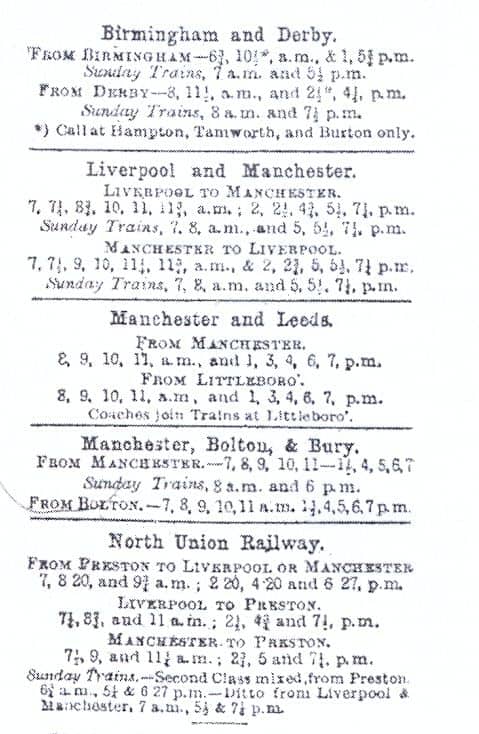 |
The Cannock Chase Colliery Comany's locomotives. 297-8. 3
illustrations
A previous effort made by the G.W. Railway to obtain Parliamentary
powers to construct a mixed gauge line from Wednesbury to the Cannock Chase
coalfield failed in 1854, as a result of opposition from the rival South
Staffordshire Railway. The railways ultimately constructed by the C.C. &
W. Railway comprised about 11 miles of single track consisting of four branches
radiating from Chasetown to New Hayes, Anglesea Siding, Heath Hayes Colliery
and Brownhills (Midland) respectively and the undertaking as then existing
was therefore a purely local one serving the Cannock Chase Collieries. Physical
connection was effected with the L.M.S. Railway (L.N.W. section) Littleworth
Extension Line at New Hayes and with the Walsall-Lichfield line at Anglesea
Siding, situate between Hammerwich and Brownhills (High Street) stations,
whilst the Brownhills branch joins the Midland Section branch line from Aldridge
immediately North of Brownhills (Watling Street) Station. A further connection
with the Littleworth Colliery Tramway of the L.N.W. Section was also made
at Conduit Colliery Junction by means of a short spur line off the Brownhills
branch.
Passenger traffic had never been operated over any section of the Cannock
Chase and Wolverhampton Railway, its activities being confined almost exclusively
to the conveyance of coal from the Cannock Chase group of collieries. The
line was, however, equipped with a system of semaphore signalling,
Three classes of locomotives were in use then, the oldest being saddle tank
engines of the 0-4-2 wheel arrangement built by Beyer, Peacock Company and
having the following dimensions :-
Coupled wheels .. 4 ft. dia. Trailing wheels 3 ft. dia. Cylinders (two inside)
14 in by 20 in 'Working pressure 125 lb. per sq. in. Heating surface (tubes
and firebox) 645 sq. ft. Hourly evaporation 2,400 lb. approx. Water capacity
640 galls. Coal capacity 2½ tons Weight in working order 28 tons Total
length overall 25 ft. 6 in. There were originally five of these locomotives,
the names, dates and makers' numbers of which are shewn below:-
McClean 1856 (28)
Alfred Paget 1861 (204)
Chawner 1864 (462)
Brown 1867 (794)
Anglesea 1872 (1211)
Brown was withdrawn from service and scrapped in 1926, but the other
four engines were still in use. No running numbers were allocated to these
locomotives and the names carried by them are those of various personages
who have served on the company's board of directors. They are of handsome
design and closely resemble the engine Knighton constructed by the
same builders for the Knighton Railway in 1861 (see Locomotive Mag.
for February, 1936). Fig. 1 illustrates one of them as then running. The
next locomotive to be dealt with is a six coupled saddle tank with inside
cylinders built by Sharp, Stewart Company (Makers' No. 2643) in 1876. It
is known as No. 6, and on account of its limited fuel accommodation this
engine normally runs with an improvised tender, in the shape of a small coal
wagon specially adapted for the purpose, attached. Its dimensions are as
under:
Coupled wheels 4 ft. dia. Cylinders 16 in by 24½ in. Working pressure
145 lb. per sq. in Heating surface (tubes and firebox) 971 sq. ft. Hourly
evaporation 3,500 lb. approx. Water capacity 900 galls. Coal capacity of
tender 5 tons Weight in working order 30½ tons Length overall-·
Locomotive 28 ft. 5 in Tender 13 ft. 10 in, Total 42 ft. 3 in.
Fig. 2 illustrates this locomotive, which, it will be noticed, is almost
identical with the engine Pontypool which at one time ran on the West
Somerset Mineral Railway and was an earlier production of the same builders
(see Locomotive Mag. for July, 1914).
The last addition to the Cannock Chase stock was a six coupled saddle tank
engine built by Kitson and Company in 1913 (Makers' No. 5036), and named
Griffin after Robert Griffin, who was chairman of the company for
several years until March 1913. There are no special features about this
locomotive which had coupled wheels of 3 ft. 7 in. diameter, two 16 in. by
22 in. inside cylinders, a boiler pressure of 150 lb. per sq. in. and heating
surface of 902 sq. ft. (tubes and firebox), an hourly evaporation of 3,500
lb., a water capacity of 900 gallons, a coal capacity of 2½ tons, and
weighs 36 tons in working order. In common with the rest of the company's
engines its chimney is ornamented with a copper rim, whilst the dome is of
polished brass. It is illustrated in Fig. 3.
Although, with one exception, the whole of the Cannock Chase locomotives
were over sixty years old, they were maintained in excellent condition and
continued to perform useful work. They were painted dark blue and lined out
in white, the names being carried on neat brass plates affixed to the sides
of the tanks. In common with all other colliery undertakngs a large number
of coal wagons were owned, but the only other rolling stock in use are some
brake vans made out of covered goods wagons, and a few flat wagons fitted
with brakesman's sentry boxes, The locomotive running shed and repair shops
were located at Chasetown.
In conclusion, the writer is indebted to the Directors of the Cannock Chase
and Wolverhampton Railway for permission to publish this article and to M.J.
Foggo, the general manager, for verifying and amplifying certain information
contained therein.
30 tons bogie flat wagon. London Passenger Transport Board. 299.
illustration
Photograph illustrates a bogie tlat wagon built by the Gloucester
Railway Carriage and Wagon Company for the Permanent Way Department of the
London Passenger Transport Board. It will carry a distributed load of 30
tons and has a tare weight of 17 tons, 14 cwt., 3 qrs. The whole of the
underframe including the built up main centre girder is electrically welded.
The length over buffers is 52 feet 7 in. and over head-stocks 50 ft. U in.
The width over solebars is 7 ft. 11 in. and over stanchion sockets 8 ft.
6 in. The bogie centres are 33 ft. 6 in. apart. The height from rail level
to top of floor is 2 ft. 8 in.
Pullman car services 299
Owing to WW2, several of these services had been withdrawn, but there
were a number still running on the Southern Railway. There the cars had been
thoroughly "blacked out" and provided the only method of travel during the
hours of darkness in which it had been possible to dine and read one's paper
in comfort under present conditions.
A unique piece of research. 299
It is known that in September, 1829, a locomotive was sent off by
Robt. Stephenson & Co. for the Baltimore and Ohio Railroad. Warren in
his Century of locomotive building, calls it "Whistler's engine",
but gives practically no details. In an old book which came to light afterwards,
there is an entry showing that it was shipped on the sloop Eraser
on 17 September, at Newcastle-upon-Tyne, en route for Liverpool. After that,
it seemed to vanish in thin air. There is no mention of it in Hungerford's
History of the Baltimore and Ohio Railroad. C.F. Dendy Marshall discovered
that the Eraser was wrecked at Peterhead on 28 September. An account
of the wreck from the Aberdeen Journal of 30 September 1829, will
be found in his forthcoming work Early British Locomotives. From a
careful study of the account, together with a nearly contemporary map of
Peterhead harbour in the Life of Thomas Telford, 1839, and a survey
on the spot, it was possible to be almost certain, within a very small area,
of the spot where the Eraser must have struck.
In August 1938, Dendy Marshall, R.E. Pennoyer, W.J. Tennant and Captain E.W.
Swan (members of the Newcomen Society), employed a diver to make a search,
which lasted three days, under the superintendence of the last-named. The
bottom is clean rock, without any sand, but in spite of this, nothing could
be found. Perhaps it was too much to expect that anything had survived, after
more than a century of gales on one of the most exposed parts of the coast
of the British Isles. The Newcomen Society, Transactions Vol. XVIII.
Early British Locomotives. by C.F. Dendy Marshall, referred to in the above
report is a new publication by the Locomotive Publishing Co. Ltd. London.
C.R.H. Simpson. Davison's Patent Locomotive.
299. illustration
Photograph reproduced shows a four-coupled tank locomotive built by
Hawthorns & Co. of Leith in 1865 for the Paraffin 'Works, West Calder.
This engine was constructed under S.D. Davison's patent (No. 312) taken out
in 1859 which related to the arrangement and oonstruction of the water tank.
This was placed bebween the frames, the plates of which constituted the tank
sides, providing, in the words of the patentees, "one solid box for the
foundation."
A necessary corollary was that the whole of the valve gear had to be placed
outside, which although rendered far more accessible, was a feature of doubtful
value on an engine of this class as it became much more liable to damage.
Leading dimensions were, cylinders 9 in. by 15 in., diameter of wheels 27
in., wheelbase 4 ft. 6 in. The boiler had a diameter of 2 ft. 6 in. and an
overall length of 6 ft. 3 in. ; it contained 64 brass tubes of 2 in. outside
diameter. The firebox, of iron, had a heating surface of 20.5 sq. ft. which,
in conjunction with the 213 sq. ft. of the tubes, gave a total of 233.5 sq.
ft. The tank held 300 gallons of water, and in working order the engine weighed
11 tons. The gauge was 4 ft. 8½ in.
Leslie Flatt, 299
Chief Mechanical Engineer of the North Western Railway, has been appointed
Deputy Chief Controller of the Indian Stores Dept.
Trade notes and publications. 300
The working display of Twin Trains at Messrs. Bassett-Lowkes London (Holborn)
Branch
This layout includes gradients for high level tracks. They have now
worked out a standard set which gives a gradient of 1 in 30 in a length of
8 ft. 6 in. and a clearance of 3 in. from the floor at the top. A number
of high and low level roads can be arranged by using these standard fitments,
which consist of straight and curved sections with special sections for points
and piers of varying heights.
The Institution of Mechanical Engineers
Carrying on the bulk of its work at a temporary address in the country,
The Meadows, Betchworth, Surrey , but the Institution building in Storey's
Gate will remain open, possibly during restricted hours, for dealing with
personal enquiries and for members or others wishing to make use of the
Library.
The Dickson all-metal laminated gasket
Consists of a number of metallic laminations, different combinations
of metal being used according to the type and service of the engine concerned.
For example, all copper is used for marine and aircraft engines, while for
Diesel engines they are either all copper or a combination of copper and
terne plate, which is cold rolled steel, annealed and coated with an alloy
of 80 per cent. lead and 20 per cent. tin. For small petrol engines combinations
of copper-aluminium, copper-terne plate and alurninium-terne plate are employed,
while terne plate is used for heavier engines. The thickness of the gaskets
is usually 0.04 in. to 0.06 in. for exhaust and intake joints and 0.05 to
0.06 in. for cylinder head joints, while laminations are 0.010 in. thick.
The manufacturers are Howard , Clayton-Wright, Ltd., of
Stratford-on-Avon,
The General Electric Company Limited
wishes to state that the Osram Companies referred to in the list of
enemy concerns are subsidiaries of the Osram G.m.b.H. of Berlin and have
no connection of any kind whatsoever, financial or otherwise, with the G.E.C.
Osram lamps and valves are made in England entirely of British and Empire
materials. The Osram trade mark for Great Britain and the British Empire
is owned exclusively by the G.E.C., which is itself an entirely British
Company.
Ruston & Hornsby Limited,
The Directors elected William J. Ruston to a seat on their Board.
Mr. Ruston is a nephew of the late Chairman of the Company, Colonel J. S.
Ruston, and is also a Director of J. Stone & Co. Ltd. of Deptford.
Westinghouse Brake and Signal Co. 300
The head office temporarily moved to Pew Hill House, Chippenham, Wilts.
Correspondence. 300
First European 4-6-0 locomotive. C. Hamilton
Ellis. 300. diagram (side elevation)
Re article on the Swiss National Exhibition a 4-6-0 locomotive for
the Gotthard Railway, built in 1883 was mentioned. I was under the impression
that the first European 4-6-0 locomotive, at any rate on the standard gauge,
was the one built at Turin to the designs of Cesare Frescot, for the Upper
Italian Railways, in 1884, a drawing of which I enclose. It was the prototype
of the famous Vittorio Emanuele class on the Mediterranean system,
later engines having alterations in detail, such as domes on the after ring
of the boiler instead of behind the chimney. I am advised by the Swiss Federal
Railways that the first Gotthard 4-6-0 locomotives, Nos. 201-2, class A 3/5
were built by the Swiss Locomotive and Machine Works, Winterthur, as late
as 1894. The Italian engine had 5 ft. 6 in. coupled wheels and two cylinders
18½ in. by 24 7/16 in. with outside Gooch link
motion. The working pressure was 156 lb. per sq. in.
Reviews. 300
Ripper's heat engines revised by A.T.Y. Kersey. London: Longmans
Green & Co. Ltd.
The continued popularity of this text book is evidence that its contents
have been appreciated by a large number of readers. It has now been thoroughly
revised and brought up to date. Many changes in steam engine design and practice
have taken place during recent years. The reciprocating type is still used
as a prime mover and will be for some time to come, but it has to a large
extent been superseded by the turbine. The internal combustion engine has
also reached an important position as a competitor for both land and marine
practice. There are over 300 pages of text liberally illustrated by diagrams
and sketches.
The locomotive engineer's pocket book. 39th Edition. London:
The Locomotive Publishing Co. Ltd.
The 39th edition of this well known reference book contains new features.
The tables and data, directories, etc., have been brought up to date. This
is a useful compendium for the pocket or desk.
Number 567 (15 November 1939)
The importance of braking. 301.
Having started a train the most important thing is to be able to stop
it, no easy matter—at least within the requisite
distance—with the high-speed trains which operated up to
the beginning of September. With automatic brakes, the increase in weight
of the standard express train during recent years has not increased the braking
problems, but long-distance schedules of 70 m.p.h. and short-distance
start-to-stop timings in excess of about a mile-a-minute have caused serious
difficulties in design and in maintenance, whether the braked weight is light
or heavy. The magnitudes of the forces involved in a full-application or
emergency stop of a high-speed train do not appear to be generally realised,
although they are amazing. For example, with an axleload of 18 tons, a stop
from 100 m.p.h. in 1,225 ft., if praoticable, would involve the dissipation
of forces up to an instantaneous maximum of 2,000 h.p. per axle, or 500 h.p.
per block, that is, 2,000 or 500 multiplied by 550 ft.-lb of work per second.
Instantaneous forces of this magnitude can be attained.
For such instantaneous rates of retardation the mechanical problems associated
with the brake gear and the wheel-axle assemblies are anything but simple,
for the mechanics of a stop from high speed are full of complex variables,
each of extremely short duration, an outstanding example of which is the
variation in friction. If it is assumed that the ratio of the braking force
to the wheel load must not exceed 25 per cent., that is, equal to the value
of the coefficient of adhesion between a wheel and dry unsanded rail, the
maximum rate of retardation will be about 5.5 m.p.h. p.s., but as a large
allowance must be made for difference in rail and adhesion conditions, say
18 to. 20 per cent. of the mean, the braking rate wi th rails under the worst
conditions would be only 3.3 m.p.h.p.s. as a top limit. From a speed of 100
m.p.h. a stop at an average rate of deceleration of 5.5 m.p.h.p.s. would
be made in approximately 1,350 ft., but a rate of 3.3 m.p.h.p.s would require
2,225 ft., an increase of 65 per cent. and more akin to the quickest actual
emergency stop. During such stops the rate of deceleration would vary greatly,
and some form of deceleration controller would be essential. In order to
obtain high-speed stops with consistent regularity without fear of wheel
sliding it is becoming common to apply sand to the wheel treads whenever
a full application is made.
Important though the mechanical problems may be, they certainly do not outweigh
those associated with the adequate dissipation of the heat generated,. a
side of the braking art which is linked indissolubly with maintenance and
repair, and also with frictional variations. Flames, let alone sparks, have
been known to stream out from tread blocks in the course of emergency stops
from three-figure speeds. It is this question of heat which has led to the
general elimination of the drum brake on European high-speed railcars, and
the substitution of disc brakes or special forms of tread blocks. Yet, strangely
enough, America is just discovering the non-tread brake, and one high-speed
train—the General Pershing
Zephyr—has been fitted with a disc form experimentally.
Drum brakes, and disc brakes, too, seek to take advantage of the constant
coefficient of friction of such materials as Ferodo, but the opportunities
of gettmg rid of the heat are so limited that on the Danish State Railways
16 per cent. of the entire mamtenance costs of the first four Lyntog
diesel-electric trains were due to brake drum lining renewals. On the
Belgian National Railways an increase of three to five minutes of certain
timings reduced the drum brake lining costs by nearly 50 per cent. In France
attempts have been made to use the advantages of cast iron and special friction
materials by using articulated blocks comprising both substances.
The high retardation rates possible with electro-magnetic track brakes cannot
be used fully, because of purely railway considerations, such as points,
crossmgs, track circuits, sanding and the like. As braking forces, apart
from such novelties as wind brakes, are dependent upon the wheel and rail
conditions, It is the pneumatic-tyred vehicles which can be stopped most
quickly, as many bruised travellers will testify, and actually deceleration
rates up. to 13 m.p.h.p.s. have been recorded With Michelin cars, that is,
well over half the rate of g, or 32 ft: per sec. per sec., which results
when the retardmg force is equal to the weight bemg braked.
4-6-4 tank locomotives, Federated Malay States. 302,
illustration
Supplied by North British Locomotive Co. to specification of W.F.
Wegener Chief Mechanical Engineer under supervision of Crown agents for the
Colonies. Fitted with A.L.E. rotary cam poppet valve gear and smoke
deflectors.
Lightweight passenger stock. 302-3.
For presentation at the American Summer Meeting of the Institution.
of Mechanical Engineers which was to have been held m New York, W. A. Stanier,
vice-president, prepared a paper on lightweight passenger rolling stock,
describing developments which have taken place in the last seven years on
the London, MIdland and Scottish Railway.
As the author pointed out .in his introduction, due to limitations of axle-weight
m this country the tractive effort of a six-coupled engme is in turn limited
to about 40,000 lb. w.hich fixes the maximum weight of a passenger train
at 600 tons. We may remind our readers that, even if considerations of keeping
the train weight within the power of the locomotive do not anse, weight reduction
is still a desirable aim, for the lower the train weight the greater will
be the acceleration and retardation and the lower the fuel and track maintenance
costs.
Weight reduction may normally .be effected by the use of light
alloys—usually a high-priced procedure—or
as in the case of the stock described in the paper, 'by scientific design.
It was stated that the normal British passenger coach consists of a steel
underframe surmounted by a timber body, in some cases with outside panels
of . sheet steel; this type of construction which results m. the weight per
passenger seat m a third-class corndor coach being about 1,600 lb. has, WIth
minor refinements remained comparatively standard for some time but since
1932 serious attempts have been made to reduce weight by new methods, and
de- parture from. the traditional British standard form of construction is
gradually taking place. The introduction of electric welding and the availability
of suitable high-tensile steels have been the corner stones of recent progress
and have permitted a freedom in design formerly unattainable. Timber has
been gradually eliminated, resulting in an increasing identiftcation of the
under frame and body, the all-steel coach having a weight of about 500 lb.
per passenger seat.
This result was greatly contributed to by combining the body side and underframe
into the form of a Vierendeel truss; this truss in a simplified form consists
of a rigid frame incorporating parallel top and bottom booms with equal sections,
and a number of vertical columns which are rigidly connected to the booms,
to transmit bend- ing moments as well as tension, compression and shear.
Regarding the body in this manner, the main under frame members form the
bottom boom of the truss, the roof structure forms the top boom while the
body side pillars perform the functions of the columns.
The author proceeded to analyse this arrangement and explained in considerable
detail the method of calculating the stresses in the different members, diagrams
being included to show the shearing force and bending moments of coach components
constructed on this principle. Turning to the oonstructional side it was
pointed out that although the conditions of limited production prevail, unit
assembly had been achieved on new lines, but based to some extent on the
construction of the old type of wooden car. As already mentioned, the
possibilities of fabrication by electric and spot welding have been extensively
employed; considerable press work is involved and jigs are largely
used—the latter are a necessity as apart from the time
saving effected they ensure the attainment of the degree of accuracy necessary.
While the stock described in the paper was built for use on the electrified
Liverpool and Southport section of the L.M.S., as the author pointed out
the principles involved appear equally applicable to main line stock, although
after each new step forward a period of consolidation is desirable in which
to study behaviour of the vehicles. Particulars of overload tests were described,
these being made on the finished structure and although of an exacting nature,
involving 100 per cent. overload, no greater variation than
1/16 inch occurred in the door pocket openings, the maximum
deflection of the solebars under the condition mentioned being
5/16 inch.
Referring to the direction in which future progress may be sought it was
suggested that as public demand for comfort in travel is always on the increase,
it is possible that the bottom of the curve of total weight per passenger
has been reached, but for operating economy it is desirable, if possible,
to avoid any upward trend in tare weights. This puts the designers and
constructors on their mettle in devising further savings in weight on the
purely structural portion of the vehicles and in this sense progress is unlikely
to be arrested. The body and under frame are already merging one into the
other, suggesting a modified form of tube as a further line of
development.
Some aspects of railway progress as they affect locomotive development.
303-5. illustration
Ordinary expresses. Engine loading schedules as applied by the LMS;
load limits as applied by Great Western and Southern Railways. Local passenger
trains.
L.M.S. two-cylinder 4-6-0 mixed traffic locomotive (class 5P5F) No. 5158 Glasgow Yeomany fitted with Manson tablet pick-up apparatus for working between Perth an Inverness. illustration (photograph). 305
L.N.E.R. 305
A record load of 721 tons was hauled by 2-6-2 mixed traffic engine,
Class V2.
"First class" travel. 305
London Passenger Transport Board withdrew first class from all services
except those to Aylebury and Watford (Met.). The French State Railway
Administration abolished first class on suburban and local trains, but retained
on long distance express trains. In 1846 vthe Great Western Railway had 107
first class, 103 second class and 18 third class carriages.
Ambulance trains. 306-7. illustration
A century of Austrian locomotive practice. 307-8
Continued in next volume page
129.
L.I. Sanders. Carriage and wagon design and construction. III. The
bogie. 309-11
Continued in next volume page 13.
Early methods of wheel making, 312-13. illustration, diagram
Photograph of flangeless wheels from Great Western Railway Lord of
the Isles. The diagram shows how the wheel was built up by making the spokes,
followed by a segment of the rim. Welding demanded the greatest skill.
C. Hamilton Ellis. Famous locomotive engineers: XIII:
Samuel W. Johnson. 313-18. 5 illustrations (including portrait)
See also letter from W.B. Thompson on green Midland engines
on page 357 and from James Bell
Lighting of trains test on L.M.S. 318
The first test of methods for the lighting of passenger compartments
on long-distance trains during the "black-out" hours, was carried out on
the L.M.S. Railway's 16.50 Euston to Heysham express on Monday, 30 October,
This experiment follows research on the part of the railway companies, the
Ministry of Transport, and the Home Office. The system tried out on the Heysham
express can only be applied on main line trains; the greater number of stops
made by suburban trains, together with the universal use of compartment doors
on suburban stock, renders it impracticable for application to such services.
Separate experiments are, however, being carried out by the railway companies
in conjunction with Government departments with a view to seeing whether
it is possible to provide a better standard of lighting in suburban trains.
The standard of lighting tried out affords sufficient interior illumination
for reading even small type. The opalescent light shades previously used
are replaced by black shades which throw the light down directly over the
passenger seats, whilst the windows are painted all round on the outside
with a four-inch black border. In addition, close-fitting blinds are installed,
which are kept drawn during the hours of darkness. Owing to the difficulty
of obtaining the necessary materials it will not be possible to introduce
the improved lighting on all main line trains for several months at least,
but at least eight of the principal expresses will be equipped and running
by now. The newly-equipped trains will be operated at first on the most important
services running, during the hours of darkness, between principal centres
of population. It is intended that these improved lighting facilities will
be available on all main line trains. It is pointed out that the success
of the present experi- ment depends to a large extent upon the co-operation
of the travelling public for whose benefit it has been introduced,
L.N.E.R. (G.N. Section) . 318
The Hatfield-St. Albans branch which was closed for passenger traffic
at the outbreak of war has now been re-opened. The suburban train service
between King's Cross and Moorgate has been suspended since the commencement
of hostilities, all local trains being now run to and from King's Cross terminus
or terminated at and started from Finsburv Park. The L.M.S. through service
between Broad Street and G.N. suburban stations has also ceased to operate.
The Finchley (Church End) and Edgware branch has been closed but in this
case a special service of buses is running in lieu of the passenger trains.
The passenger service over the new line between Hertford North and Hitchin
is also discontinued for the present.
L.M.S. Rly. (Midland Section) . 318
The through' passenger train service to. and from Moorgate had not
been operated since the start of the war.
L.N.E.Rly. (G.C. Section) . 318.
The local train service between Marylebone and stations on the Met.
and G.C. Jt. 1ine still remained suspended, but the service to and from High
Wycombe and intermediate stations had been augmented.
G.W.Rly. 318
Automatic train control had been installed throughout the main line
between Paddington and Penzance, Fishguard and Chester—a
total distance of 2,852 miles.
Soviet Railways. 318
Building an experimental locomotive with an internal combustion engine
as well as steam. Th: fuel would be coal with a gas generator. The total
power estimated 4,000 h.p., 2,500 being supplied by the gas erigme and 1500
h.p. by the steam engine.
Lionel Wiener. Steam carriages Belgian State Railways.
319-22. illustration, 6 diagrams (including 5 side elevations)
Belpaire designs, including guitar boiler.
Some aspects of braking. 322-4. 2 diagrams, table
Early work on friction between brake shoes and the wheel included
that by Coulomb and Morin who experimented from 1781 until the early 1830s;
H. Bochet; Galton and Poirée
A new automatic drifting valve. 325-6. diagram
J. Stone & Co. device fitted to Kenya & Uganda Railway 4-8-4+4-8-4
Beyer Garratt.
Travelling rail welder. 327, 2 illustrations
For repairing rails, rail ends, crossings, and switches, as well as
general engineering repairs, Lincoln self-propelling electric welder, operated
by a self-contained petrol engine, and running on the track at any desired
speed, up to 30 miles an hour. Essentially the design consists of a steel
platform truck, carrying a 6-cylinder petrol engine, with radiator at the
front, an electrical generator of the separately excited variable voltage
type, providing current for the welding, an auxiliary electrical generator
for working electrical tools,l:nd a D/C propelling motor. All the necessary
electnc welding equipment is provided, including 1,000 feet each of welding
cable and tool cable, both carried in an enclosed cable compartment at the
back.
Correspondence. 327
Some early Pullman Cars. J. Pelham
Maitland
Canon Fellows' article in the October Issue affords a valuable synthesis
of information on this. subject. It only contains, however, the briefest
references to the two baggage cars constructed by the L.B. & S.C.R. in
1888 to match up with the Pullmans. These were 6-wheeled vehicles with Pullman
type clerestory roofs and other similar details externally. No. 29 was also
remodelled to conform to the outline of the cars when the end platforms were
finally abolished, and early in the present century was repainted in the
cream-and-umber livery then adoptel as standard by the Pullman Co. It lasted
in service, I believe, until 1913, when it caught fire owing to a short-circuit
from the dynamo, and was subsequently broken up. On the other hand, No. 80
remained in its original condition until the absorption of the L.B. &
S.C.R.. by the S.R. became effective. It had not been in service' for many
years previously, and did duty as a Carriage-Examiners' Lobby at Lover's
Walk Carriage Shops, Brighton, until the end. I can never recollect ever
having seen this van on the road, although I can well remember the cars with
the open platforms referred to by Canon Fellows, and also the very elaborate
panelling and gold lining which, survived until about 1902.
As long as the L.B. & S.C.R. lasted, the 10.05 down train and the 13.20
up, on weekdays, were colloquially- referred to by the operating staff as
"The Pullmans." Vans 29 and 80 were designated the "Pullman Pups", by the
same people.
It should also be recorded that the Sunday Pullman Ltd. train was designated
in certain Victorian circles as "The Sabbath Breaker" for some years after
its inception. See also letter from Stephenson V. Knight
on page 357
Bridgen's Time Tables. Reginald B.
Fellows. 327-8
Mr. Brown is quite right in thinking that the words at the foot of
page 11 of Bridgen's Time Tables "Corrected October 18, 1839" indicate that
there was an earlier edition. The Time Table was advertised in The Railway-
Times of 5 October 1839 as follows:-"Alteration in the arrival and departure
of Railway Trains Oct. 1 1839. This day is published price 6d. done up in
cloth in so concise a way as to be adapted for the waistcoat pocket Bridgen's
Time Table of the London and Birmingham, Grand Junction . . . Railways .
. ."
So it was some weeks ahead of Bradshaw's publication of 19 October. But James
Drake of Birmingham was much earlier, his maps and tables were first published
in July 1838. The time tables showed the trains between London and Denbigh
Hall and between Rugby and Birmingham with the connecting coach service,
also the trains on the Grand Junction, and the Liverpool and Manchester Railways.
New editions were issued in October and November 1838 and the latter included
five railways. The maps were very elaborate, but the publication "in a case
for the pocket" cost 2/-.
E. H. Dring read a paper on "Early Time Tables" to the Bibliographical Society
in 1921, and the following is extracted from it:—
"Among other contemporary time tables are:
(]. Bridgen of Wolverhampton).
Bridgens/Railway /Time Tables/or guide to Railway Traveling / London:/ Simpkin Marshall and Co., .. ...../........../ Price sixpence./ Corrected to Aug. 1, 1840.
A note on p. 2 states that this is a new and improved edition. In 1904 there was exhibited at the Old Manchester Exhibition at Manchester an edition of this Time Table on page 11 of which there was printed 'Corrected October 18 1839'. a day earlier than the date of the earliest Bradshaw."
L.M.S.R. appointments. 328
E.A. Milne, Works Superintendent, Barassie to Carriage & Wagon
Assistant, Glasgow; W.R. Ford, Shed Foreman Birkenhead to be Assistant Locomotive
Superintendent, Carnforth..
Number 568 (15 December 1939)
The continued need for efficiency. 329
Some engineers, during the embryonic period of training and in the
earliest stages of their subsequent careers, the definition of efficiency
is strictly confined to the thermal and mechanical implications of the term.
Individuals in this category, and also others who are uninformed and equally
misguided, are prone to decry the low thermal efficiency of the steam locomotive,
unmindful of the fact that its ultimate efficiency, that is, in the: economic
sense, is high and has enabled it successfully to compete in many fields,
as it will undoubtedly continue to do for many years, with rival forms of
motive power which are more efficient in the purely technical applications
of the word. As his experience widens, however, the young engineer realises
that efficiency goes far beyond mere technical considerations. In its widest
sense it may be defined, possibly a trifle loosely, as the performance of
given work in a satisfac- tory manner with the lowest ultimate outlay of
money. Railways have been all too familiar with this interpretation, and
the necessity for its translation into practice with accompanying, true economies
in every direction, over a long period of financial stringency. A timely
reminder was recently issued by an executive of the L.M.S.R. to the effect
that control of the home railways by the Government is neither excuse nor
reason for any relaxation of effort in the search for increased efficiency,
wherever it may be attained. There can be no disagreement with this statement,
which must indeed be accepted as an axiom and applied universally. The
achievement of greater efficiency, always essential to ensure :financial
stability, is imperative when war is being waged under modern conditions
with victory as the goal; economic and military considerations are then of
equal importance, and waste on the home front is as much a potential cause
of defeat as, for instance, shortage of troops or ammunition in a vital sector
of the front line.
With statistics and other data available, the managerial and technical staffs
of the railways are well able to observe changing trends and, after' analysis,
to meet them by instituting new methods of administration and operation,
improving exist- ing arrangements, modifying lay-outs and shop processes,
and by effecting improvements in design. Although it does not necessarily
happen, it is at the same time possible that with a broad outlook available,
some details which are capable of improvement may be overlooked. Given the
intelligent application of his powers of observation and deduction, the man
who uses these details in the course of his daily work is well qualified
to' suggest improvements for them. On some railways he is encouraged to do
so by monetary awards for all suggestions which are put forward and, after
investigation, given effect. There are two very important points to be considered
in the working of all suggestions schemes. In the first place the staff should
be encouraged to make suggestions, with identical opportunities for reward,
in connection with the work of both their own and other departments; enginemen,
for instance, are frequently able to suggest improved methods of operation,
train control and signalling, and operating staff, alterations in the design
of carriages and wagons from the functional aspect. Secondly, the reward
should bear some proportionate relation to the savings effected by the suggestion
adopted; there is no encouragement for further suggestions to be made when
a man, knowing full well that his suggestion has saved his employers literally
thousands of pounds, is rewarded with a sum of, say, five pounds which, by
comparison, is beggarly. If in such cases the' maximum amount of the award
is arbitrarily limited, then suitable promotion in addition might be considered.
Suggestions which are well beside the mark as regards practicability should
not be coldly discouraged, or even merely formally acknowledged; this is
a psychological error. It is quite possible that the originator, unless basically
irresponsible, will go on and in time produce a really valuable suggestion.
Further, the examination of an ap- parently worthless suggestion frequently
opens up an incidental matter and leads to an improvement in a direction
far removed from that originally intended; even so, progress has been made.
The search for, and attainment of efficiency and true economy must continue
ceaselessly, irrespective of the method adopted.
L.N.E.R. 329
S. L. Baister to succeed W. Wells Hood as Works Manager at Shildon
and Faverdale.
Some aspects of railway progress as they affect the locomotive
department, 330-3.. 2 illustrations
Continued from page 305). (All references to operating features referred
to in these articles are necessarily on a pre-war basis). Through
Engine-Workings. The suitability of the modern locomotive for longer continuous
service has had a considerable effect upon operating practice. Obviously
this capacity for greater continuity of work presents an opportunity to the
operating authorities, of which they have not been slow to take advantage.
Engine-workings have been revised so that the number of changes en route
are reduced, continuous runs of as much as 400 miles by one engine being
now a commonplace. Again, an engine is booked to work a train for about 100
miles to its destination; whereas previously the train-destination was also
that of the locomotive, the latter now picks up another working in the same
direction, and at the end of that, yet another, working perhaps four or five
such stages before setting out (even by an indirect route) on the return
journey to its home depot. This return journey, again, may be made by successive
stages. This system has necessarily involved the abolition to a large extent
of the practice whereby particular sets of enginemen were kept to a particular
locomotive; as many as eight or a dozen different sets of men may now handle
a main line engine between its leaving its home shed and its return there.
Moreover, some of these men may be only "terminal relief" crews who take
over from the arriving crew because the latter's time is up, and who take
the engine to shed (not necessarily its home shed) for coal, water and other
attention pending its being taken out again by a fresh crew. Here again,
standardisation of locomotive types has proved extremely valuable, because
it is essential to the success of any system of intensive work- ing, that
the engines used shall be of types with which all the different crews are
likely to be familiar. This practice could not have been suc- cessful in
the early days of British railway amal- gamation, because of the widely divergent
designs of locomotives then in use and the difficulty of in- structing "foreign"
crews in their efficient working without spending a great deal of time in
training.
The greater continuity of locomotive user is, of course, a considerable asset
to the Operating authorities, since it enables a substantial aggregate saving
of time previously allowed at intermediate stations for the changing of
engines—although it has to be recorded that full advantage is not always
taken of this factor.
This policy also has the effect of reducing the importance of some of the
intermediate running- sheds, as does the allied practice of working many
branch line trains, previously powered from a local depot, by engines of
main line type which spend their terminal margins in this manner. Modern
Signalling Developments.
In the decade that immediately preceded the Great War it appeared as
though a degree of finality had been attained in British signalling, at any
rate in the indications displayed by night and by day. The introduction of
the day colour- light signal, in 1920, proved however to be the beginning
of a series of developments that have had a marked effect in train operation.
A number of these improvements belong solely to the realm of signal engineering
technicalities; a proportion have been designed to facilitate traffic operation,
by the concentration of control at important junctions and termini in one
or two large signal boxes instead of a large number of small ones. But any
effect upon the locomotive department of schemes in the above categories
is at the most an indirect one, and in- teresting though they may be from
the scientific point of view there are other developments of far greater,
in fact vital importance to the men on the footplate; it is these that are
dealt with in the present article. British practice only is covered; signalling
on the Continent and farther afield is in many cases based upon different
principles altogether, and to consider them would be impos- sible in the
space available. During the last twenty years there has been a general seeking
after more logic in signal indications, a trend towards making things simpler
for enginemen, and among numerous developments of this kind none was more
needed than the alteration in colour of 'the distant signal warning indi-
cation, from red to orange. Until the advent of the three-position signal
there was strikingly little to distinguish a distant from an absolute stop
signal; the fishtail arm is recognisable from a fair distance by day, but
very few railways made any attempt to differentiate between the two at night.
Both displayed a red light in the "on" position, and a driver had to depend
on his knowledge of the road to determine whether it was an absolute stop,
or only a warning signal that he was approaching. In some cases an illuminated
"fish-tail" was displayed to the right of the red light, and the former Furness
Railway used a flashing red light for the warning indication. Such practices
were, h ever, isolated rather than general. Signal Anomalie A bolishe . When
signals displaying three separate indications ,"all-clear," "caution," and
"stop" were introduced into this country,. orange was chosen as the colour
for night indication of the "caution" aspect. The practice was extended when
the first three-aspect day colour-light signals were installed.
From that it was a logical step-though one that involved an immense amount
of work-to change the night indication for the "caution" position in all
distant signals from red to orange; at the same time the painting of the
semaphore arms was changed from red to yellow. Although tolerated for so
many years, the prac- tice of allowing a driver to ass signal relating to
his particular road th was dis laying a red light, was neither helpfu nor.Iog
ical. ce it was abolished, attention was turned to other anomalies of a similar
kind. In the middle nineteen- twenties many existed; a number still do, but
one particular problem became aggravated when colour-light signalling was
first installed at big termini and junctions. To cut to a minimum hand and
verbal signalling of shunt movement it be- .came, for a while, the practice
to use a large It may be argued that the experienced driver would have no
difficulty in distinguishing these subsidiary lights from his own; that,
however, is only the distant signal argument in another form, and since then
welcome steps have been taken to remove the objection. The trouble occurs
princi- pally when colour-lights are used for the main run- ning signals,
and in such cases two different solu- tions have been found. On the Southern
Rail- way, and on the electric railways of the London Passenger Transport
Board, disc signals are being standardised; to avoid the use of coloured
lights of any kind at night, and at the same time to dis- play the same kind
of indication, these discs are floodlit after dark. Floodlighting is, however,
only possible at stations where a supply of electric- ity is available, and
at country stations and other places outside the colour-light areas a compromise
. When placing distant signals further out, to give longer braking distances
for high speed trains the new distants are usually colour lights, arranged
for long sighting. number of miniature light signals, the majority fixed
at ground level. Though not so penetrat- ing as the main signals the light
thrown from these ground indications was far more powerful than anything
used hitherto for the same purpose, and the driver of a train making a running,
as opposed to a shunt movement, had to pick his way, as it were, among a
veritable carpet of red lights. The difficulty was made worse by the diffused
nature of the light-beam; in the case of a main running signal this is fairly
concentrated in order to obtain the maximum length of range, but a shunt
signal has often to be observed from a wide angle and the optical system
was designed accord- ingly. In consequence, when approaching a big centre
the whole array of ground signals facing the direction of approach were seen
from the foot- plate. has had to be made for night working. Oil lamps provide
the necessary lighting, but the spectacle glasses in the discs-particularly
the reds-are made so small that the chances of confusion with a running signal
are very slight.
In the North-Eastern Area of the L.N.E.R., what is termed the "position-light"
signal has been adopted for shunting purposes in all recent power installations.
In the case of the ground signals two white lights are displayed horizontally
for "stop," and the signal to proceed on a shunt movement is given by two
white lights dis- played diagonally. The same indication is given by day
and by night. For the daytime, fairly strong lighting is needed to give a
distinct indication; the background of the permanent way is not ideally suited
to the display of white lights, and it is not usually possible on account
of structure gauge limits to. provide a sighting board. At night the conditions
are reversed, and in all recent installations apparatus has been provided
far re- ducing the voltage on the lamps at night sa that the white lights
are not so bright as to. interfere with the sighting, at lang range, of the
main running signals.
Reducing Number of Signals.
The desirability of avoiding as far as possible the need for a driver to.
pass a red light of any kind, whether it relates to. his particular route
or not, applies with even greater force at junctions, both at high speed
layouts and in the approaches to. stations with many platforms. In the heyday
of semaphore signalling, the approach to. a busy traffic centre was marked
by a forest o f signal arms, changing after dark to. a galaxy of lights.
cators have been tried, but the one that seems likely to. have the widest
application is the so-called theatre-sign indicator. This, as its name suggests,
has a large number of small lamps arranged an a square black display ground;
various combinations of lamps are selected electrically in order to. produce
the platform numbers or route symbols required, and a very clear indication
results. A smoky front glass does not appreciably reduce the visibility,
indeed in same instances tinted glass is used to. soften dawn the brilliance
of the letters. This type of indicator is, however, only suitable for slow
running locations, such as the entrance to. a big yard; the indication dis-
played could not be recognised far enough away to be of any use to. a driver
approaching a junction at 80 m.p.h.
Even before the ooming of colour-light signalling some of these picturesque,
though somewhat over-whelming displays had disappeared, and a com- paratively
few arms, with route indicators, functioned in their place. But though excellent
in theory the route indicator was not an easy appli- ance to produce in a
form complying with all the strictures of practical railway operating, A
roller- blind, or a series of enamelled plates, was more or less satisfactory
for daytime, but at night, unless the characters were exceptionally large,
illumination was difficult whether performed by a light shining through a
stencil, or by a half-hearted attempt at floodlighting from the front. The
plates, too, quickly became grimed with smoke. With the introduction of
colour-light signalling, quite a variety of internally illuminated route
indi-
High Speed Junctions. The signa' of high seed junctions has been the subject
of m eh contro ersy, and it has always been found diffic t obtain a full
measure of agreement as to how much or haw little inforrna- tion should be
given to. the driver af an approach- mg tram. One school of thought advocated
what has been termed "speed signalling" -a system that tells a driver only
the speed at which he may run, and gives no indication, geographically or
otherwise, of the direction in which he is being routed. Other practices
give varying degrees of information. From the engineman's point of view the
fullest information as to the state of the road ahead is desirable, for then
he can run with confidence and get the best aut of his engine when///incidental
delays or unusual routing takes place. Nowadays this is generally recognised,
and the latest developments in both semaphore and colour- light signalling
are proving very successful in the operation of heavy and fast traffic.
The problems concerned in the signalling of a junction where high speeds
obtain are best understood by taking a specific example, an ordinary double-line
junction of two main routes "Line A" and "Line B," both us - express trains;
there is a passenger statio earby, nd through this sta- tion there are loops
n both the and down sides. A train approaching the junctio in the facing
direction can pass through on anyone of the four routes: via fast road to
Line A: via loop road to Line A; via fast road to Line B ; via loop road
to Line B. As a specific instance the case of a high- speed express passenger
train may be considered. Normally it passes at about 80 m.p.h. via the fast
road, to Line A, and on 99 out of 100 occasions no kind of delay is experienced
at this station. Then comes a day when, owing to some special train working,
the down fast platform road is occupied and the train standing there cannot
be cleared in time to give the "flyer" its normal road. One is naturally
anxious to cause as little delay as pos- sible and the kind of message to
be conveyed to the driver is: "We're putting you through the loop to-day.
All the signals are off, but don't forget there is a 35 m.p.h. speed restriction
over the points at both entering and leaving ends." Conveying Information
to the Driver.
How is such a message best to be conveyed? To be really effective it must
be given to the driver at the distant signal, for then he has time to pre-
pare accordingly. Considering first the signalling of such a layout with
semaphore arms, it is the practice in some localities to provide only one
dis- tant arm, and to lower this only when there is a dear straight run through
on the main line. In the particular case under consideration the distant
arm would be at "caurt:ion," and the driver, not knowing what to expect,
would slow right down preparing to stop. The signalman in his turn would
probably keep the home signal arm relating to the loop at danger until the
train was fairly close, to ensure a slow passage over the turnout, and the
driver, seeing this signal clear in front of him, would crawl on expecting
to be stopped at the starter-a-the latter at present obscured by the sta-
tion buildings. At last he would "get the road" but even so might proceed
to the next block post less energetically than the circumstances require,
simply because he half expects to be delayed again.
An alternative method of signalling, and one that is finding favour, is to
provide" splitting" distant signals. In such a case as that under consideration,
there would probably be at least two, and most likely more distant arms.
It would thus be possible to advise a driver, not merely that he was being
diverted from the straight run, but also that the loop line was clear throughout.
The geographical disposition of the actual arms in relation to one another
provides a clear indication of the route to be followed, and at the same
time gives an adequate reminder of the necessity for reduced speed over the
turnouts. At night the position of the green light .in relation to the other
three, which are showing orange, acts as a route indicator and a speed indicator
as well. This system may be criticised on the grounds that it increases rather
than decreases the number of signal lights dis- played; but with semaphore
arms and oil lamps, this is not a serious disadvantage, and in the majority
of layouts it is more than outweighed by the improved operation that it
permits.
Illuminated Direction Indicators.
With day colour-light signals it is of the great- est importance to reduce
the number of lights displayed simultaneously. Here a beam of infinitely
greater intensity is being dealt with; the lenses are much larger, and the
range at night is something over two miles. In designing, a parallel shaft
of light is aimed at, but in actual practice there is a certain amount of
"spread." At close range this is negligible, and the beams from two adjacent
Lights are well separated. But seen from a mile off it is a different picture;
the spread is sufficient to cause a certain ,intermingling of the beams,
and in the case of a splitting signal, one unit of which is showing green
and the other red, it might well be difficult to decide which route was
signalled, since the optical mixing of red and green produces a white light.
It is to avoid the use of splitting signals in colour-light territory that
illuminated directional signs have been introduced. Indicators of this type
have been installed on the L.N.E.R., the L.M.S.R., the Southern, and the
surface lines of the L.P.T.B., and it seems probable that the type will come
to be recognised as the standard junction route indicator in this country
for use in colour-light areas.
Indication is given by a row of white lights pointing away from the lens
of the colour-light signal. At a junction, the route of least diverg- ence
from the main line is indicated by a row of lights inclined at 45 degrees
to the vertical; the next route to the left, or right, is indicated by a
horizontal row, pointing to the left or right of the main signal as the case
may be; a third, and still sharper divergence, is indicated by a row of lights
pointing downwards at 45 degrees to the vertical, though the locations needing
this sign have so far proved somewhat rare. For a main line move- ment, 110
indication whatever is given, the driver of an express seeing displayed only
the green light of the main signal. For a diverging movement, very complete
information can be given as to the state of the road ahead, and by the display
on the main signal of an indication, such as a "double yellow," more res
tricti ve than the "green," there is conveyed a valuable reminder of speed
limits over turnouts. Illustrations: L.M.S.R. Hatch End up distant Photo.
O.S. Nock, Starting signals at Waterloo, Southern Railway. The signal for
the left hand train is clear, and the theatre sign indicator displaying M.L.
(main line).
High-speed lightweight trains.
334-6
Continued in next volume page 18.
C.T. Ripley, Chairman of the American Society of Mechanical Engineers, Railroad
Division, presented before that Society a comprehensive paper with the above
title. The subject was one claiming considerable interest on both sides of
the Atlantic, and, we consider, merits a comparatively detailed report. The
author commenced by drawing attention to the expansion of travel habits during
the last twenty years, which growth was attributable to the development of
cheap cars and the construction of suitable roads. Proceeding to trace the
evolution of coach construction it was stated that in 1900 the 60 ft. wooden
passenger car, seating about 80 passengers, weighed about 40 tons or 1,000
lb. per passenger. In the interests of safety, designs were changed first
to include steel underframes, and in about 1910 to all-steel construction.
Various parts were also increased in size and weight in order to secure greater
strength and durability, until in the 1920's the 80 ft. passenger car seating
about 70 passengers weighed approximately 80 tons or 2,300 lb. per passenger.
About 1930 still further weight was added, due to the introduction of
air-conditioning equipment, weighing about 5 tons. As a result of this continued
increase in weight of passenger cars, as well as a gradual increase in the
speed of operation, the size of steam motive-power units steadily increased.
Track structures and bridges had to be made stronger to carry these heavier
locomotives and cars, and thus there was, from all of these angles, an increase
in the cost of operating passenger trains, while at the same time the total
traffic was diminishing and there was a continual demand for lower rates
to save the remaining traffic.
About the same time some new structural materials became available for use
by the car builders, namely, aluminium alloys, stainless steel, and various
so-called low-alloy high-tensile steels. Because of these developments the
railway engineers and the car manufaoturers started active work in the design
and construction of new trains of a lighter type for main-line operation.
The first of these were small trains consisting of three or four cars with
600 h.p. Diesel engines located in the head car. They were made as light
as possible to hold down the power requirements and to enable them to. compete
with buses and private automobiles by giving cheap transportation. The cars
were of non-standard height and same were narrower than the standard. They
were streamlined to reduce power requirements and also. to make an appeal
to. the public, already educated to. such design by automobile developments
The reaction of the travelling public was so favourable that there was an
immediate demand far mare elaborate and larger trains for longer runs, with
sleeping accommodations and other features for maximum comfort. Low first
cost was soon last sight of in this development. Interior decorators designed
the mast elaborate fittings and the trains were built with as many as 14
cars with power units. totalling as much as 5,400 h.p. and auxiliary power
far the cars of 1,200 h.p. A few of these trains were powered with streamlined
steam locomotives but there was little change in the design of these locomotives
from the old type except that large: drivinlg wheels (84 in.) were used together
wIth higher steam pressures (300 lb. per square inch) and larger tenders
to. reduce delay in taking fuel and water. They also had roller bearmgs and
some other refinements in desi
gn, Mast of the early trains had articulated cars because at was thought
that this design reduced weight and gave better riding conditions. It developed
however that neither of these factors proved to be important. There was a
definite disadvantage in articulation particularly on long runs, in that
standard cars could not be mixed with such cars In case of difficulty, such
as a bearing or wheel failure, a car failure might became a train failure.
In the last few years practically all the lightweight cars have been built
as individual units with standard floor and coupler heights and standard
outside dimensions, so that they can be associated with any standard car.
The weights of these cars were reduced about 40 per cent. from those of the
conventional structural- steel cars and thus four-wheel trucks could be used.
The only standards far design strength avail- able at the time mast of these
cars were built were the provisions of the United States Railway Post Office
mail-car specifications. These specifications were first prepared in 1912
by a group of repre- sentatives of the Post Office Department, the Master
Car Builders Association, and the car manufacturers. It was required that
all postal cars meet these specifications. While other cars were not required
to. meet them, practically all pas- senger-train cars were designed at least
to. these requirements.
In 1938 new specifications, based an the United States Railway Post Office
mail-car specifications, were produced to cover practically all types of
con- struction with all types of materials. The major provisions of bath
the earlier and 1938 specifications were, first, a minimum strength of
centre-sill construction based an 400,000 lb. buffing static load and a factor
of safety of two, and second, a minimum strength of end construction to protect
against telescoping action. This latter required minimum section moduli for
vertical end members and minimum shear values far their top and bottom
connections. There were also. numer- ous other limitations of stress in frame
members. Cars built to. meet these specifications have rendered excellent
service with a remarkably good record in the protection of passengers under
wreck conditions. As a consequence when lightw construction was started in
about 1931 these specifications were used as a minimum requirement, even
though there were no rules of the American Railway Association or of the
Government setting such limitation. However, a feeling developed that because
of the operation of lightweight cars between heavy cars in trains, it was
necessary for the Association of American Railroads to set up more detailed
specifications to cover the construc- tion of all passenger-train cars built
in the future, giving particular attention to prevention of damage from
telescoping. A committee of the Association of American Railroads has recently
developed these new specifications and they will probably govern all new
construction of passenger cars. While these new specifications are generally
based on the Railway Post Office specifications, they include some major
changes: They provide for a centre-sill strength such that an 800,000-lb.
load applied on line of draft will not produce any permanent deformation.
The Railway Post Office specifications contained only a stress limita- tion
and permitted the load application to be divided between the coupler line
and the buffer line. This change will probably result in the ad- dition of
more material than is now used in centre sills of lightweight cars designed
with high centre sills and buffers, with little compensating benefit from
added protection.
Light weight is almost a necessity for' high- speed operation in order to
hold down the size and cost of power units, as well as the cost of opera-
tion. This is particularly true with Diesel-electric locomotives with their
high first cost. Experience indicates that 450 lb. per h.p. (including weight
of locomotive) is a proper design ratio for high- speed operation. Some of
the new trains have a power ratio as high as 550 lb. per h.p. but the maintenance
costs appear to run higher on such trains. In order to secure satisfactory
performance on high-speed schedules, it is necessary to have some reserve
power in the locomotive because some delays are inevitable and extra power
is needed to make up for lost time. While the schedules may indicate that
maximum speeds of only about 90 m.p.h. are required, actual opera- tion requires
at times speeds of 100 m.p.h. or even higher. This fact must be taken into
considera- tion when designing locomotives and trains for this type of service.
Several of the early trains were built of aluminium alloys but in recent
years the majority of them have been built of stainless steel or low- alloy
high-tensile steel. The major claims for the stainless steel are lower weight
due to higher physical properties, better welding by the auto- matic Shot-Weld
process, and high resistance to corrosion. Stainless steel does not have
to be given paint protection of any kind, which reduces both first cost and
maintenance cost. Its polished surface gives an attractive modernistic appearance
to the cars and is easily cleaned. In high-speed operation the sandblast
effects of particles from the ballast or right of way damages paint finishes
quite rapidly. The low-alloy high-tensile steel advocates claim that they
secure equally low weights for lower costs.
It appears that a weight of about 100,000 lb. for an 80 ft. coach is entirely
practicable with full safety to passengers. If too much space for extra luxuries
is provided, part of the advantage of lightweight construotion is lost, as
the important factor is the weight per passenger carried. Due to higher operating
speeds, the design of passenger-car trucks is a most important factor. The
former six-wheel trucks were not entirely satisfactory at these increased
speeds, and doubt existed in the minds of some as to the possi- bility of
securing good riding qualities with four- wheel trucks. The weights of the
new car bodies were so low that only four axles were necessary to carry the
load, affording further opportunity for weight reduction by the use of four-wheel
trucks. Exhaustive experiments were made by various rail- roads and manufacturers
resulting in the develop- ment of many new features of truck design with
a decided improvement in riding characteristics. Among these new features
were the use of softer springs with greater deflections, hydraulic shock
absorbers to control both lateral motion and vertical spring reactions,
multiple-spring systems in triple-bolster trucks, and roll stabilisers. The
use of cylindrical tread contours on wheels to reduce the nosing of trucks,
and the grinding of treads to secure true rotundity and concentrici ty, were
both conducive to easy riding. Balancing of the wheels was also practised
to some extent. In an effort to reduce noise in the cars, rubber or other
semi-resilient materials have been introduced in various parts of the trucks,
such as pedestals, spring seats, and centre plates. The mounting of the brake
cylinders on the trucks instead of the body has also reduced the noise produced
by the brakes. Improved insulation of car floors, as well as the sealing
of windows, has also made a marked improvement, but there is still need for
further noise elimination.
The introduction of high-speed lightweight trains brought many new problems
in braking. The stopping of these trains within reasonable distance is a
difficult problem. While the car weights are less, individual wheel loads
are as high and in some cases (particularly with the articulated type) higher
than with the old heavy cars. In order to reduce the stopping distance, there
have been a number of changes from "former practice, such as truck mounting
of brake cylinders which increases rigging efficiency, much higher braking
ratios (some as high as 250 per cent.), decelakrons to reduce pressures as
the train slows down and thus prevent sliding of wheels, automatic sanders
acting only in emergency application, and electro-pneumatic control. In some
cases the very high brake ratios resulted in considerable wheel and brake-shoe
trouble. With all of these improve- ments there is still a question whether
emergency stopping distances are as short as they should be. In both steam-
and Diesel-powered lightweight trams, the locomotive weight is a large percentage
of the train weight, but in most cases locomotives do not do their full share
of the braking. The steam locomotive is particularly lacking for three reasons:
First, there are often some unbraked wheels on engine trucks for operating
safety; second, the large spread between light and loaded weight of renders
makes it necessary to design braking power on the basis of light weight;
and third, enginemen have to relieve engine brake pressure frequently to
guard against the loosening of dnvmg tyres due to heating. The Diesel is
better in that all wheels are braked and the spread between light and loaded
weight is relatively small, but the srriall-diameter wheels are so highly
loaded that the braking ratio must be limited in order to protect the wheels
from damage. It would be advantageous if Diesel-electric locomotives had
a supplementary dynamic electric brake such as is used in some electric
locomotives as well as in the new experimental turbo-electric design.
The Diesel-electric locomotive is more commonly used in these new high-speed
streamlined trains than is the steam locomotive. It is claimed by some that
this is chiefly due to the interest of the public in a new type of power,
but the users apparently' have. good engineering arguments to support their
choice. The advantages claimed for the Diesel are: First, high availability;
second rapid acceleration because of high tractive power at lower speeds;
third, low maintenance costs; fourth, low fuel cost (usually less than half
that of steam) ; fifth, lower rail stresses. The steam locomotive is 'less
e:xpensive,' costing about $37 per h.p. However, It is harder on track at
high speeds due to the dynamic augment produced by over- balance in the driving
wheels. It appears that a radical change in the design of the steam locomotive
is n~essary to make incapable of fully competmg with the Diesel m this service.
The important objects of such redesign should be the securing of a more constant
torque and the reduction of track punishment. Three outstanding locomotives
of new design are under construction or in service, namely, the 5,000-h.p.
turbo-electric being manufactured by .the General Electric Company for the
Umon Pacific Railroad, the Baltimore and Ohio Railroad's four-cylinder engine,
and the Pennsylvania Lines' four-cylinder high-speed engme. All of these
new types are experimental but they indicate a trend towards a type of steam
locomotive having more constant torque. A step still further in this direction
is involved in a new Baltimore and Ohio design, which includes individual
axle drive.
Manufacturers of Diesel-electric locomotives 'have an advantage in that they
produce a practically standardised product and thus can reduce cost ./ through
line production. On the other hand almost no two lots of steam locomotives
are the same. Each order means a new design with re- sulting high costs for
engineering and production. This also means higher cost for and larger stocks
of repair parts. American railroads have made a marked advance in the
standardisation of freight cars but there has always been strong opposition
to any plan for standardisation of steam locomo- tives or passenger cars,
due mainly to differences of opinion among different managements.
The riding quality of Diesels is better than that of steam locomotives They
also provide smoother-riding trains as their high tractive effort at low
speeds enables them to start and accelerate trains more quickly and smoothly.
Steam locomotives have an advantage in that more horse-power can be put in
one unit. It may be noted that the increase in horse-power is secured with
a lower percentage of increase in first cost and weight, that is, both the
cost and weight per horse- power are lower for the 4-8-4 locomotives than
for the 4-6-4 type. The maintenance cost per horse-power should also be somewhat
lower for the 4-8-4 locomotive. It is true that any number of Diesel units
can be coupled and controlled from one cab, but this increase in number of
units means increased first cost and increased weight. A 2,500 h.p. Diesel
unit would appear to be a desirable size for heavy service, particularly
in mountainous territory, but this does not appear practicable at present.
Fayle, H. The Cork, Bandon and South Coast Rly. and
its locomotives. 336-8. 7 illustrations
Concluded from page 277. Nos. 9 and 18 were two 4-4-0T supplied by
Neilson & Co. in 1894: WN 4741 and 4740 and cost £1725 each. They
were rebuilt with trailing radial axles and extender bunkers. They became
GSR Nos. 480 and 481 and were scrapped in 1935/6. Two Baldwin Locomotive
Works 0-6-2STs were supplied in 1900. They had 18 x 24 in outside cylinders,
4ft 8in coupled wheels,1179 ft2 total heating surface and 18.79
ft2 grate area. Fig. 21. They were withdrawn in 1914 (No. 20)
and 1912 (No. 19) . The Beyer Peacock 4-6-0T wngines began with a prototype
No. 11 (WN 4752/1906). It cost £3165 had 18 x 24in inside cylinders;
5ft 2½in. coupled wheels and a total heating surface of 1182.5
ft2. It was very successful and led to a further seven: Nos. 14
WN 5265/1909; No. 15 WN 5434/1910; No. 20 WN 5616/1912; No. 19 WN 5822/1914;
No. 4 WN 5954/1919; No. 8 WN 6034/1920 and No. 13 WN 6077/1920. No. 4 cost
£4389 and is shown in Fig. 22. They became GSR Nos. 463-70 and
were class B4. No. 467 was rebuilt with a Belpaire boiler with superheater:
894 ft2 total heating surface (invcluding superheater), pop safety
valves, 22.1 ft2 grate area and 150 psi boiler pressure. The livery
had been sage green. The Timoleague & Courtmacsherry Light Railway had
three locomotives at the time of take over: 0-6-0ST Slaney was a Hunslet
product acquired from Robert Worthington, the contractor for the line. It
had 12 x 15 in cylinders and 3ft coupled wheels. It was scrapped in 1914.
St. Molaga was an 0-4-2T from Hunslet WN 520/1890. It had 10½
x 16in cylinders and 3ft 3in coupled wheels. Argadeen was a Hunslet 2-6-0T
WN 611/1894 with 14 x 18in cylinders, 3ft 6in coupled wheels and 539
ft2 total heating surface. In 1925 it was rebuilt at Broadstone
with a Belpaire boiler off Imp a Kerr Stuart railmotor with 623.26
ft2 total heating surface and a grate area of 9.5 ft2.
P.C. D[ewhurst]. L.M.S.R. locomotives: a history of
the Somerset and Dorset Joint Railway. 339-41. 8 illustrations.
Continued in next volume page 43.Twenty
eight 4ft 6in Johnson 0-6-0s known as "Scotties" as first came from Neilson
& Co.: these werre rebuilt with Midland boilers from about 1896 Fig.
41 shows a Vulcan Foundry locomotive No. 43 in is rebuilt state. Fig. 42
shows Neilson No. 37 with new boiler (which had a total heating surface of
1133 ft2 and 140 psi boiler pressure. Fig. 43 shows No. 25 with
q Johnson boiler and Fowler chimney and tender with handrail and footsteps
at rear of tender. Between 1905 and 1910 Deeley boilers were fitten to Numbers
56-61. Fig. 48 shows No. 58. There was some recycling of boilers amongst
locomotives. Fig. 45 shoows No. 36 with a Fowler chimney. Fig. 46 shows No.
57 as No. 34 (notess clackboxes on front ring of boier barrel. Deeley boilers
werre fittedd to "Great Northern" Nos. 19-24. These had 1¾ in.
tubes; a total heating surface of 1035 ft2 , a grate area of 14.6
ft2 and 160 psi boiler pressure. There were no safety-valves on
the dome, and those over the firebox were of the Johnson-Deeley pattern having
a lock-up auxiliary (directly-loaded) valve in front of the Ramsbottom columns;
the whole being encased in a conspicuous casing of polished brass, later
painted over. The original set of Neilsons were all scrapped by 1922, Nos.
33 and 34 in 1914 and Nos. 35 to 38 in 1922. Of the Vulcan's. of the first
batch, Nos. 39, 41 and 43 were scrapped in 1922, 1925 and 1914 respectively,
whilst Nos. 40, 42 and 44 became Nos. 67, 68 and 69 in 1928, later becoming
L.M.S. Nos. 2886-7-8 in 1930; of the second batch, all Nos. 25-28 were scrapped
by 1929, No. 27 going in 1914, and Nos. 25, 26 and 28 in 1929, whilst of
the third batch Nos. 46, 48 and 51 were scrapped in 1925, 1922 and 1925 respect-
iv~and Nos. 47, 49 and 50 became TOS. 70, 71 and 51 in 1928, and later LMS.
2889-90 and 2885. Finally, engines Nos. 56-61 were renumbered Nos. 33-38
in 1922 and although No. 33 was scrapped in 1928 engines Nos. 34-38 were
rebuilt with Midland Railway G.5 pattern (Belpaire) boilers in 1929, 1929,
1928, 1927 and 1928 respectively, becoming L.M.S. Nos. 2880-4 in 1930. The
new boilers carried 160 lb. pressure and were fitted with Ross pop safety
valves. New frames and new cylinders were also supplied, but the original
cabs were retained. Fig. 47 shows No. 2884 as rebuilt. The eleven engines
of this class taken over by the LMS were, therefore, Nos. 34-38, 51 and 67
to 71, and they became Nos. 2880 to 2890, as mentioned above. They were all
scrapped between 1931 and 1933, the last three to go being Nos. 2881-3, so
that the class is now extinct. These engines, which were all classed 1, were
replaced on the Burnham Branch line by the Class "3" 0-6-0s to be mentioned
hereafter. Fig. 48 is of interest in that it shows engine No. 68 (formerly
No. 42) when it had become L.M.S. No. 2887 still with a John- son boiler
but with a Deeley chimney of the same tall pattern as used on the 0-4-4 tank
engines and 0-6-0s when reboilered with Deeley boilers.
L.N.E.R. 341
Thc following further V2 class (2-6-2) engines had been built at
Darlington: Nos. 4840, 4841 and 4842, another V2 class, No. 4846, and a V3
(2-6-2T) No. 390, had been built at Doncaster, and two J50 class (0-6-0T)
Nos. 595 and 598 had been built at Gorton. The following engines had been
withdrawn: Nos. 824, 4-6-0 class BI5, No. 1874 4-4-0 class DI7, No. 4126
0-6-0 class J6, No, 1825 0-6-0 class J24, and No. 6178 0-8-0 class Q4.
On the 4 December a revised train service was brought into operation. Many
additional trains were being run throughout the L.N.E.R. system and a mid-day
service between London and Edinburgh was available again.
The passenger services on the Louth and Bardney line, the Horncastle branch
and between Leeds (Central) and Barley had been restored as also had the
L.M.S. Co.'s through trains between Broad Street and the GNR suburban lines.
The entire L.N.E. passenger service between Derby (Friargate) and Burton
on Trent, Uttoxeter and Stafford had however been withdrawn.
An early Taunton locomotive.. 341. illustration
Although the outside-cylinder 4-4-0 locomotive was, in its day, extremely
popular in America, inside-connected engines of the same wheel arrangement
were also built, but in comparatively small numbers. The reproduced illustration
is of one constructed by the Taunton Locomotive Works, of Taunton, Mass.
in 1852. This engine, which had cylinders 16 in. by 20 in., was in the service
of the New London Northern Railway, a subsidiary of the Central Vermont Railway
which in turn was a subsidiary of the Grand Trunk Railway. As a Westinghouse
brake air pump was fitted, the photograph could not have been taken earlier
than the 1870's, by this date a number of changes had probably been made
to the engine, which carried the name T.W. Williams.
Phillipson, E.A. The steam locomotive in traffic. IV. Locomotive depot
equipment. 342-3. 2 illustrations, diagram
R.A. Lister & Co., of Dursley. Petrol driven auto trucks including
flat trailer and one with rotating brush and sprinkler; also electric capstan
and oil dispenser.
G.W.Ry. 343
Several 0-6-0 goods engines had been reconditioned at Swindon and
Eastleigh for service overseas,. including Nos. 2403, 2461, 2480, 2518 and
2533 which also did service abroad during 1914-18. No. 5089 Westminster
Abbey, was a new 4-6-0 express engine, and the following had also been
completed at Swindon Works, Nos. 3808 to 3813 (2-8-0), Nos. 2208 to 2210
(0-6-0), Nos. 3635 to 3645 (0-6-0PT), and Nos. 3104, 4130 to 4136 and 8108
(2-6-2T).
Union Pacific R.R. 343
Fifteen 4-8-4 passenger and fast freight locomotives had been completed
by the American Locomotive Company. They had cylinders 25 in in diameter,
6 ft. 8 in. driving wheels-with a tractive force of 63,800 lb. The tenders
were carried on 14 wheels and carried 23,500 gallons of water.
Dublin University Engineering Society. 343
E.C. Bredin, Chief Mechanical Engineer, Great Southern Railways, delivered
his inaugural address to a meeting of the members in Dublin on 17 November.
The title of his lecture was "The Design of a Modern Locomotive," which had
mainly for its subject the G.S.R. 4-6-0 3-cylinder 800 class locomotive.
The design was referred to in detail and a number of interesting lantern
slides were shown. Engines running on other lines were also described and
illustrated and comparisons of two cylinder and multi-cylinder engines .were
made. At the conclusion of the lecture R.G. Booth (presumably president)
proposed and W.H. Morton seconded a vote of thanks. Mr. Morton also added
some interesting remarks about the employment of Diesel locos. and railcars
in Eire.
[Obituary]. 343
Regret to announce the death of A.B. Boxall. He was the staff of Sir
Douglas Fox and Partners for 58 years.
Morris, O.J. Standardising Southern Railway locomotives.,
Central Section. 344-7. 2 illustrations, 2 diagrams
Continued next Volume: see page 93. (12).
The "Small Vulcans", 0-6-0, Class C2. Ashford features introduced including
pop safety valves
smokebox door and the stem-mounted whistle. From the style of chimney, it
will be obvious that bath of the engines illustrated have the 1 ~22 single-plate
smokebox, the rivet heads of which are now left shewing. Bath have had their
Westinghause hoses removed, but the air brake still operates the blacks an
engine and tender and there is a "through" vacuum pipe far tl~e train. One
or two minor differences are also visible, such as the extended cab roof
and cased-in coal rails an N a. 2535, and the undisturbed positioning of
the whistle an No. 2555. It is interesting to note that, in 1932 the farmer
was at work with D. Marsh's sa fety-valves partially covered by a Stirling
-casmg .
The story of the Small Vulcans is cample~ed by adding that, in 1905, D ..
Earle Ma~sh expenment- ally repainted No. 537 m black WIth a red auter and
a white inner line, and at the same time he -d id aut No. 446 in the same
colour with the -double red line that was afterwards adapted. Under Cool.
Billintan's "uniform livery" scheme -of 1922, several of the class, such
as No. 555, ap- peared in the passenger colours. The first of the C2's to
be scrapped, S.R. Nos. 2452 and 2530 disappeared in the autumn of 1935 since
when the following have also gane the 'Way'af all locomotives at the dates
in brackets, 'No. 2433, first of the class built, (12/36), Nos. 2439 (4/37),
2531 (3/36),2542 (1/37), and .2555, last of the class built (12/37), leaving
seven in service at November 1st, 1939. Owing to a -shortage of spare bailers
for this .class, someof these survivors are due to be rebuilt into the Im-
proved C2x class in the near future. (To be continued
). .* To this extent, the opposing statement on p. 83 of Vol. XLIII must be modified, the engines shewn in Figs. 12 and 13 having single-plated smokeboxes of the original external dimensions, but not of the original (i.e., air- jacketed) type. t See Vol. XLIII, 15/9/37, pp. 291-2. t "Locomotives of the L.B.S.C.R.. 1903-1923", p. 62. § The first "replacement" of a girder-stayed by a direct- stayed firebox was made by D. Marsh on the B2 4-4-0 "Gollsmid," which, however. was then provided with a whistle mounted on a stem projecting through the cab roof, as on the B4 class.
WAR TIME LIGHTING. 347
The aim of railway engineers has been to restore white lighting of an intensity
sufficient to afford a reasonably good reading light. This they have succeeded
in doing by in- stalling shades specially designed to throw the light below
the level of the carriage windows. To prevent the emission of any light it
is necessary for the blinds of all carriage win- dows to be kept drawn throughout
black-out times and a border of black paint has to be applied to the windows
to prevent light showing behind the blinds.
What this involves can best be appreciated when it is remembered that the
British railways have some 40,000 carriages with about 250,000 compartments.
The total number of windows to be painted with a black band is about 1,500,000
and many of these have to be fitted with blinds or curtains. In each compartment
at least two of the special shades have to be fitted to the lights, and it
is . estimated that at least 500,000 shades ~ill have to be fitted.
Locomotives for India Again 347
N aur issue far March 15, 1937, we wrote criticising the suggestian put forward
by an Indian contemporary that locomotives should be built in that country
an the broad economic grounds that imparts were necessary far the pay- ment
of exports and that in consequence if India failed to maintain a satisfactory
basis of impart she would in the end find herself unable to sell her exportable
surplus. We alsa commented .upan t~e stimulation to trade that would be
expenenced If aut-of-date types of locomotive power were weeded out and replaced.
The subject of ha me manufacture has recently received a further measure
of prominence, bath in the Legislative Assembly as well as in the technical
press, and we make no excuse far returmng to it on account of its own importance
to the British locomotive- building industry. The idea of national self-
sufficiency is no new one; it is 'a plain negation of economics as it fails
to take into account the fact that trade must consist of buying as well as
sell- ing on a. world-wide basis if the wealth af nations is to be maintained;
it, unfortunately, is fa voured by certain schools of political thought and
is in all probability one of the major causes of the present trouble. Let
it be admitted at once that India can build her awn locomotives without any
serious difficulty and has in fact already done sa to a very minor ex- tent,
but if this is to become the national palicy- and here we quote our contemporary,
"The Indian Railway Gazette" - "it would be necessary to ensure that the
Legislative Assembly, in a mood of pardonable enthusiasm to foster locomotive
construction, does not commit the country, as was done in the last decade,
to expenditure far in excess of actual requirements." The corollary to the
above quotation is that if once committed to this policy money will be spent
like water by the Legislature in order to ensure its official success and
that orders placed abroad will naturally cease.
It is perhaps an opportune moment to refer to recent locomotive building
for India. The appaintment and Report of a substantial Committee recruited
in this country and charged with the task of reviewing the design and alleged
shortcornings of certain types of locomotives standardised by the Indian
Railway Board is now history. Their remarks cannot be construed as encourag-
ing to the existing arganisatian; in fact, the Rail- way Member (Sir Andrew
Claw) summing up the debate an the Report in the Legislative Assembly (Sept.
11, 1939) said that the Committee had made it clear that in its opinion there
was an error of judgment in neglecting the warning of consult- ing engineers
and in proceeding without trial with the purchase of sa many engines at one
time. Anather member had referred to this purchase as unwarranted and a huge
waste of public money ; the outsider may well wander what the total sum will
amount to when the whole matter is at last satisfactorily adjusted. We ourselves
recall the description of two experimental engines for India read before
the Institution of Locomotive Engineers on Dec. 15, 1937, in which the experi-
mental alterations were so numerous that it would be practically impossible
to trace any variation in result, whether good or bad, to its true source.
It would seem therefore that there is room for im- provement in the ideas
of the Board and we would like to suggest that as regards locomotives, design
and manufacture should be left to the C.M.E. re- sponsible with the consulting
engineers as a revis- ing authority. It is surely better to call in the great
experience and knowledge available in tbis country at the beginning of things
rather than at the end; in addition, the C.M.E. of the railway concerned
is, and always must be, in closer con- tact with realities and requirements
than a remote ami standardising board, however capable its members may be.
We would remark in conclu- sion that the Report indicates in our opinion
that in the absence of standard conditions of track and haulage the advantages
of standard types of loco- motives intended to cover what really amounts
to a continent are somewhat illusory
. AN OLD SWEDISH ENGINE. 348
The accompany photograph, taken by Mr. Sven Nygren of Vaxjo , Sweden, shows
a link with the earliest days of railways in Scandinavia. As is well known,
there were mining railways in Sweden before public railway trans- port was
begun by the Government in 1856, and locomo- tives were built for these by
the Munktells Machine Works in the early 'fifties and after. The second
locomotive in Sweden, now preserved at Tom teboda, was a Munktells engine,
built at Eskilstuna in I855. The example shown came from the same works in
1864, and is still at work on the K6ping-Uttersberg-Riddarhyttan Railway,
which has the peculiar gauge of 3t ft. (Swedish) equal to 3 ft. 7 in.
2·4·01' xe. 2 "UTTERSBERG," KOPI0:G-UTTERSBERG·RIDDA· RHYTTA"f RLY., SWEDE"f.
Certain details appear to have been copied from early Beyer, Peacock locomotives for the Swedish State Rail- ways, such as the sandbox. The practice of placing the dome on the first ring, though also reminiscent of Beyer design. as in the Metropolitan tanks, was employed by Munktell from the first. The cab, the Coale safety-valves, and the spark-arresting chimney are later addition
Saltcoats Accident, L.M.S.R. 348-9
The Ministry of Transport issued the Report of its Inspector, Col.
A.C. Trench, on the railway accident at Saltcoats on 5 August 1939, when
the 12.30 Arran Boat Express from Glasgow (Central) to Ardrossan was derailed
at Saltcoats with the loss of two lives, in addition to the two enginemen.
The train consisted of seven non-corridor bogie coaches, all of which, except
the rear coach, were fitted with shock-absorbing buffers. The locomotive
was a standard class 4, 0-6-0 tender loco., No. 4315. The train was travelling
on the former Caledonian Railway Co.'s Glasgow-Cathcart-Ardrossan line,
constructed in the days of fierce competition with the Glasgow and South
Western Railway for the Arran traffic but now only used for freight traffic,
except during the summer services, when it is used for a few boat trains
in connection with the Arran and Isle of Man steamers. There is a permanent
speed restriction of 40 miles an hour on this line as between Lugton and
Ardrossan. The Inspector finds that the train was travelling at not more
than 30 miles per hour at the time of the accident, having just previously
observed two temporary speed restrictions for subsidencies. As a result of
the accident, the locomotive and its tender and five coaches left the rails
on the outside of a slight curve immediately after passing over a road bridge,
the locomotive and tender falling down the embankment, followed by three
coaches—two coaches were derailed on the top of the embankment, and
the two rear coaches remained on the rails. The two rear compartments of
the second coach, and the three front compartments of the third coach were
partially telescoped, and it was in these compartments that the casualties
occurred—none of the passengers in the front coach were injured. The
Report states that the track was in good condition, the outer rail was worn,
but was perfectly safe for the speed-limit laid down. The evidence proved
that a stone or stones had been placed on the outer rail at the point where
marks on the rail showed that derailment had begun, a deposit of crushed
stone 1i inch thick remaining on the rails after the whole train had passed
over it, and that a piece of slag from the ballast had also been on the rail
at a point 55 yards before the mark of derailment. A certain amount of
trespassing along the line had been customary—especially by
children—access to the line being obtained at the foot of the abutment
of the road bridge mentioned above. The Inspector clears the enginemen of
all blame, and finds that the derailment was due to the stones placed on
the line and fixes the responsibility for the accident on those who placed
the obstruction on the line.
2·6·2 suburban taxk locomotive, Eastern Bengal Railway.
348
We are indebted to Macaulay, Works Manager of the Kanchrapara Locomotive
Shops, for the accompanying photograph of a recently rebuilt 2-6-2 tank engine
taken over from the Great Indian Peninsula Railway in I928. The engine was
built in I914 by the North British Locomotive Co. and a similar one built
by the Vu1can Foundry was illustrated and described in our November 1914
issue.
Locomotives of the Appleby-Frodingham Steel Co. Ltd. Group 2. Appleby
Works locomotives (till 1934). 349
The locomotive fleet of the Appleby Ironworks, before its association
with the Frodingham Works in 1912, comprised eight units as follows:- Appleby
Loco. Old No. 1. The first loco., probably dating from the opening of the
works in 1877, was purchased from the Yorkshire Engine Co. and was of
four-wheeled saddle-tank type, with 13 inch outside cylinders and a working
pressure of 140 1b. per sq. in. This loco. bore the name The Old Mare
and was sold to a purchaser in South Wales, about the end of WW1
Appleby Loco. Old No. 2. The second loco. was of second-hand origin
and early date. Built by the Hunslet Engine Co., it was of six-coupled,
saddle-tank type, with a working pressure of 160 lb. per sq. in. and 14 inch
inside cylinders. For its time this loco. was of advanced and powerful type.
For many years it was used to handle ironstone traffic on the furnace "drops"
or bunker inclines. During the mid-nineteen-twenties, it was scrapped
Appleby Loco. Old No. 3. The third loco. was purchased from Andrew Barclay,
Sons & Co. about 1884, and was of four-wheeled, saddle-tank type, with
13 inch outside cylinders and a working pressure of 140 lb. per sq. in. Old
No. 3 was sold about the end of the WW1 period, apparently to the Rother
Vale Collieries, now another section of the United Steel Companies Ltd.
Appleby Loco. Old No. 4. The fourth loco. was purchased from the Hunslet
Engine Co., about 1890. Like all later additions to the fleet, it was of
six-coupled type and provided with an adequate cab. The working pressure
was 140 lb. per sq. in., and the inside cylinders were of 13 in. diameter.
The loco. was scrapped about 1927.
Appleby Locos., Old No. 5 and Old No. 6. The fifth loco. (No. 5
Pontypridd) and the sixth (No. 6 Pendleton) were both acquired
second-hand and are reputed to have previously served constructional work
for the Manchester Ship Canal. In this case their arrival at Appleby was
probably soon after the completion of the canal in 1894. Built by the Hunslet
Engine Co., both were of six-coupled, saddle-tank type, with working pressures
of 140 lb. per sq. in., and inside cylinders of 14 inch diameter. Scrapping
took place during WW1 in the case of No. 6, and and towards 1927 in the case
of No. 5.
Appleby Loco. Old. No. 7. The next loco. No. 7 Roseneath) was bought
second-hand about 1900. Built by the Hunslet Engine Co., it was of six-coupled,
saddle-tank type, with a working pressure of 140 lb. per sq. in., and inside
cylinders of 13 inch diameter. The date of building is unknown, but scrapping
took place about 1927.
Appleby Loco. No. 8 (No. 108, from 1933, No. 66 from 1938). The eighth loco.
was purchased from the Hunslet Engine Co., in 1909. Details are listed below:-
Steam pressure 160 lb. per sq. in. Tubes 130 at 11 in. Total heating surface
(tube and firebox) 528 sq. ft. Grate area 8 sq. ft. Tank 550 galls. Cylinders
(inside type) Diameter 14 in. Stroke 18 in. Wheels (six-coupled) Diam 3 ft.
2 in. Gross weight (full working order) 27.25 tons Adhesion ratio (gross
weight/tractive effort) 5.5 Appleby No. 8 was smaller than contemporary units
at Frodingham. The loco. has proved speedy for lighter duties, however, and
is now retained in the amalgamated fleet. (To be continued).
Some aspects of braking. 350-2
or 265 h.p. and 655 h.p. respectively, this energy decreasing to zero within 24.5 sec. and 62 sec. re- spectively. When holding the axle on a down- ward grade of 1 in 50 and 1 in 25 at a constant speed of 50 m.p.h., the energy to be dealt with is 39.7 h.p. and 92.5 h.p., or 28 B.Th. . and 65. B. Th. U. respectively. As the tyre surface with nor- mal 3 ft. wheels is 450 sq. in., and the shoe surface 2 x 46.5 = 93 sq. in., and as furthermore the heat conductivity of steel is about 33.6 B.Th.U. (f t.):' (hr)-I(deg.F)-l the heat difference within the tyre when stopping from 125 m.p.h., and thus dissipat- 36000 x 12 ing 655 h.p. will be = 236°F. per ( 450 + 93) x 33.6 inch. As indicated by the above general calcula- tion the stresses involved due to heating of the wheel can lead to deformation with resultant cracks in the wheel rim and in this respect the tests made at the University of Illinois are of interest (10). The wheels used were chilled units 33 in. in dia. and weighing 700 to 750 lb., the brake shoes being plain unflanged cast-iron ones with chilled faces, while one wheel was subject to shoe pressures of 1,000, 1,500, 2,000, 3,000 and 4,000 lb., the rest was subject to a pressure of 3,000 lb. only. With most of the tests the rim speed was kept con- stant at 25 m.p.h., and the shoe applied continu- ously for 48 minutes, this combination of speed and duration being equivalent to a wheel tread travel of 20 miles. The tests have shown that while at a pressure of 1,000 lb. the shoe wear was 0.244 lb. per 100 millions ft. lb. of work, this figure increased to 0.53 and 1.091 lb. at a shoe pressure of 2,000 and 4,000 respectively, this indi- cating the advantage of employing smaller shoe unit pressure. While the first tests were made with a wheel having a diameter variation of not over 0.001 of an inch, difficulty was experienced at shoe pressures of 1,000 and 1,500 lb., as eccentricity of the tread developed due to unequal heating. When hot the wheel was out of round up to 0.01 inch, this caused unequal distribution of heat, as the shoe did more work on the high than on the low section of the tread. After a few applica- tions at 2,000 lb., shoe material was deposited at several places on the wheel tread and glazed spots developed in these places. They caused unequal heat distribution in the wheel, probably due to a lower coefficient of friction at these spots, leading to a deformation of the wheel. A few small checks developed during the tests at 1,000 and 1,500 lb., while a few more, together with a few small cracks, were produced during 2,000 lb. shoe pres- sure tests. After the 3,000 lb. tests, a large num- ber of heat checks and cracks were found on the wheel tread, thirty-two cracks being longer than 2! in., the condemning limit specified by the Association of American Railroads. After the 4,000 lb. tests 92 cracks over 2i in. long were found, and although none extended into the throat or flange some 16 ran to the outside of the wheel rim. As up to the present no method is available whereby the surface temperature of a revolving wheel may be measured with any degree of accu- racy, no reliable conclusions can be drawn as to the relation of the surface temperature and wheel failures. Measurements made with thermo- couples inserted in the wheel t in. below centre of tread showed temperatures up to 280 and 6900 F. when applying a shoe pressure of 1,000 and 3,000 lb. respectively, the hub temperature for the same tes ts being 115 and 2150 degrees F . respectively. After a stop the wheel rim cooled rapidly while the temperature of the hub and the surrounding plate of the wheel increased within 20 and 30 minutes to 140 and 3400 F. respecti vel y, this being due to the fact that the rate of heat transfer from the wheel plate. is considered less at a stop than when runnmg. The maximum radial tensile strains shown by the tests occurred always at the outer face of the wheel, near the curved junction of the plate with the hub. In all tests the maximum radial strain produced was a tensile strain of 23,300 lb. per sq. in., which occurred when applying brake pressure of 4,000 lb. for 50 minutes at a speed of 15 m.p.h., the distribution and relative magnitude of the radial strain at both plate faces of the wheel being shown by Fig. 8. (6) Metzkow: "Glasers Annalen", 1925, p. 137; 1926, p. 149; 1927, p. 137. (7) "The Friction of Railway Brake Shoes, its Variation with Speed, Shoe Pressure, and Wheel Material." Uni". of Ill. Eng. Exp. Sta., Bul. No. 257, 1933, (8) "The Friction of Railway Brake Shoes at High Speed and High Pressure." Univ, of Ill. Eng. Exp. Sta, Bul. No. 301, 1938. (9) Nicolet et Rousselet: "Le Frein Autoregle N.R." Traction Nouvelle, 1938, p. 78. (10) Resistance to Heat Checking of Chilled Iron Car Wheels." Univ. of Ill. Eng. Exp. Sta. Bul. No. 298, 1937.
L.P.T,R. 352
On 20 November 1939t the connection be- tween the Bakerloo tube at
Baker Street and the Metropolitan line at Finchley Road was brought into
use and a through service of trains inaugurated between Elephant and Castle
and Stanmore (Met.). There are two intermediate stations on the new section
of tube, viz., St. Johns .Wood and Swiss Cottage. The former Metropolitan
stations at Lords (originally St. John's Wood), Marlborough Road and Swiss
Cottage had been closed, but it is understood that the first named will be
brought into use again during the cricket season in connection with matches
played on the Lords Ground.
A train ferry across the Danube between Roustchouk (Bulgaria) and Giurgevo (Roumania) will when ready pro- vide the long desired railway connection between the [,,'0 countries,
L.M.S.R. (Northern Counties Committee) .352
The 3 ft. gauge Portstewart Steam Tramway engine, No. 1, had been sent to
the Hull Transport Museum. It was built by Kitson and Co. in 1882. An article
on the Portstewart Trarnwav appeared in "The Locomotive" for Nov. 1927. .
OBITUARY.354
We regret to record the death of Mr. Robert Manson at the age of 83 who was
a younger brother of the late Mr. James Manson, Locomotive Superintendent
of the G. &S.W. Ry. at Kilmarnock. Mr. Robert Manson was District Loco.
Superintendent of the G. &S.W.R. at Glasgow, Ayr and Dumfries, and retired
some years ago. The financial committee of the Indian State Railway has agreed
to a sum of nearly 50 million rupees being spent on the purchase of new rolling
stock during the 1939-40 finan- cial year.
L. Derens. The High Level Belt Railway and the new stations in Amsterdam.
354-6
During the night of 15 October 1939 the old Weesperpoort station of
Amsterdam finally closed and its activities transferred to the new Amstelstation
opened early next day. Since December 28, 1843, when it was opened, as the
terminus of the then broad gauge Dutch Rhenish Railway, it has performed
its task and witnessed the many changes of traffic conditions and last but
not least, has endured the drastic alterations for temporarily adapting it
to electric traction, pending the completion of the Amstel- station. Although
not reaching its own centenary, this historic building witnessed the centenary
celebration of the Dutch railways, on which occasion the front of its arched
roof was suitably decorated, as shown in Fig. 1, with a wooden winged wheel
mounted on the national flag, flanked on both sides by the initials N .5.
with the centenary dates. The last train on the night of October 15 was an
electric train from Utrecht leaving for the Central station at 00.21. An
official ceremony with representatives of the railway company and of the
city of Amsterdam present, took place m the train. The enthusiasm of the
Amsterdam people was remarkable thousands gathered to witness the departure
of the last train, the station being filled. The police were unable to withhold
the crowds from passing the ticket barners on the second platform at which
the train arrived. The driver was carried on the shoulders of the enthusiasts
from the rear to the front of the twelve-car train, where he added his tribute
to others, decorating the head of it. At last amidst cheers and noise from
exploding detonators on the track the train
Correspondence. 357
S.W. Johnson. W.B. Thompson
On p. 315 Ellis stated that the last Midland engme painted green was.a
tank engine built in 1881. May I say that the green paint survived a little
longer? The twenty express engines built in 1882, Nos. 1562-1571, which were
fitted with the vacuum brake and ran between London and Nottingham, and Nos.
1572-1581, which had the Westinghouse brake and worked south from Carlisle,
were all painted green when new. I had a trip from Carlisle on No. 1577;
and I also remember being on a rebuilt Kirtley goods engme, No. 494, at Rugby
early in 1883, which had recently come from Derby and was painted green.
The red paint was said to be cheaper; but it seemed a pity that the green
was abandoned, for the engines never looked so well after the change.
Beauty is a matter of personal impression, but I think most people would
agree with me in saying that Johnson was the greatest artist, not even exceptmg
Joseph Beattie or Stroudley, that the locomotive department of a British
railway has ever produced. For myself, I consider that his 60 class of express
engines built towards the close of the last century were the most beautiful
engines I have ever seen on any railway in the world. To those of us who
remember the elegance of design and the spotless cleanli- ness of the Johnson
engines it is a sad experience to travel on the Midland line to-day.
S.W. Johnson. James Bell.
Re. C. Hamilton Ellis's Famous Locomotive Engineers: is he is right
in ascribing to S.W. Johnson any share in the design of N.B.R. Nos. 382-393.
I cannot distinguish any particularly Johnsonian features in the design of
these engines and the fact that they were built after his regime as Loco.
Supt. at Cowlairs had ended does not favour the supposition that the design
was his. Moreover, when they first appeared in 1866 they embodied features
which were already familiar on the N.B.R. The design of frame was precisely
similar in outward appearance to the frames of Nos. 90-95, built in 1861
by Neilson and Co. Later on, in 1865, exactly the same frame appears in the
N.B. series Nos. 341-346 built by Dubs in that year. In all these classes
the design of splashers. side-sheets, and stormboards are much alike and
came, one would say, from the same hand.
As a boy I knew No. 393 well, prior to her rebuilding. At that time she had
lost her original funnel which had been replaced by one of Mr. Wheatley's
stove-pipes, but she still retained her wealth of brass beading. When new
she must have been a very handsome engine. A clue to the authorship of the
design might be found in the fact that the 382 class all had pull-out regulators.
The other classes I mention may have had these regulators also. I cannot
say; but I am absolutely certain that the 382 class had them.
At the time when I first knew 393 she had long come down from express rank,
having been superseded by the Wheatley,· Drummond , and Holmes
engines, but she was still a speedy and reliable engine, remarkably silent,
and easy on coal and oil and Mr. Johnson, if he had anything to do with her
design, had reason to be proud of his handiwork, Signed Inspector, L.N.E.Rly.,
Edinburgh.
Early Pullman cars. Stephenson Y. Knight.
357
Re Canon S.B. Fellows and J.
Pelham Maitland's articles on the above have been of very interesting
reading to me seeing that at that time my late father, the then General Manager
of the L.E. & S.C.R., J.P. Knight, and Allport of the Midland Railway
were the pioneers of the Pullman mode of travelling in the United Kingdom.
My own recollections of these splendid trams go back to r883 when as a small
lad I can well remember being taken to and from Brighton for a trip in the
Pullman train. The early Pullmans were, as the Rev. Fellows says, of the
open end balcony type of build; they were 60 feet each long, and one could
walk the whole length of the train as wooden platforms covering the connections
between the cars were provided, the cars being coupled with Stroudley's patent
"Close coupling device" very ably set out in detail in Barry's Railway Mechanics.
There were thirty lights in the cars and the current for these came from
thirty-four Faure accumulators, charged in the first instance at a depot
in the Strand somewhere near the Tivoli Music Hall. Afterwards Houghton,
the Electrical Engineer to the Brighton Railway, put up a small charging
unit at Victoria Station for this purpose and here the accumulators continued
to be charged until Houghton brought out and invented his device for charging
the batteries from a generator, belt driven from the axle of the car. The
cost of the Pullman Train was about £12,000, and at the time
(1881) it was the most luxurious of its kind running in Europe. The cars
were fitted with what was then quite an innovation by way of blinds for the
windows, they were sprung supported and could be lowered or raised to any
desired position by the passenger. The train was also fitted with the Stroudley
and Russbridge Electric Communication which had just then been introduced
on the Brighton Railway. Henry Marks was the conductor of the train and he
afterwards became the manager of the Pullman Car Company. Two other well
known conductors of Pullmans on the L.B. & S.C.R. went by the names of
"Nutmeg" and "Fussy," but to this day I am unable to trace the origin of
these names. Mr. Snow must also be remembered for he was for many years in
charge of the Pullman running in the Newhaven boat train.
The Rev. Fellows does not mention the standard livery of the cars. They were
finished in a deep umber brown, with black and gold lining. The names of
the cars were Albert Edward, Victoria, Beatrice, and
Louise. When the 1888 Pullman Vestibuled Train made its appearance
the old Pullman Train was divided up and the cars put into service on different
trains running between London and Brighton; for many years, in fact well
into the 'nineties [1890s], Albert Edward and Victoria ran
in the 5 p.m. down and the 08.45 up expresses to and from Brighton. "Nutmeg"
and "Fussy" had charge of these cars, and I remember their very courteous
attention. Hot breakfasts of a limited menu could be had on the 08.45. train
from Brighton, teas could always be served, also other liquid refreshments
too numerous to mention.
About the year 1879, a Pullman Drawing Room Car was run in the 15.55 ex Victoria;
this train ran to Portsmouth Harbour, having a through connection to the
Isle of Wight, reaching Ventnor at 20.24. The Pullman adventure in this respect
did not turn out to be a success and it was withdrawn.
Response from Reginald Fellows see Volume 40 page
25.
Timothy Hackworth and the locomotive. A.V.
Green, 357-8
Re books James Watt,
Engineer and Craftsman, by H.W. Dickinson, and the other
Timothy Hackworth and the Locomotive
by R. Young. Kindly allow me through the "Locomotive" to draw attention
to a remarkable discrepancy in these two books. On page 6 of "Timothy Hackworth"
note the portrait entitled William . Murdoch by courtesy of the Secretary,
James Watt Centenary Memorial. Then compare Plate VIII on page 86 of James
Watt, Craftsman, which claims to be that of Matthew Boulton, from the
oil painting by Wm. Beechy, in possession of the Boulton family. facing.
page 114 of the same book we have Plate X representing Wiilliam Murdoch,
from an oil painting by Graham Gilbert, by permission of the Museum and Art
Gallery Committee of the Corporation of Birmingham. Where does the error
lie? I am inclined to the belief that it is in Mr. Young's book. On the other
hand, it is strange that neither Mr. Young nor his friendly critics observed
such a mistake.
The matter I trust, through your good offices, will be brought under notice
of such bodies as the Stephenson and Newcomen Societies, as well as the
Institution of Locomotive Engineers, etc. It is of importance that posterity
be furnished with accurate history, and I shall endeavour to do my share
in this respect. If I can furnish information about Australasian railways
to bona-fide members of engineering and historical societies, I shall deem
it a pleasure and a duty to help them:
Reviews. 358
The design of flat plates. C.C. Pounder. Epsom: The Draughtsman Publishing
Co. Ltd.
The new edition of this booklet has been enlarged and contains much
information of value to designers of flat plates.
The oil engine manual.-London: Temple Press Ltd.
This book, written by two members of the technical staff of The
Oil Engine, provides in concise and well-illustrated form information
on the principles and practical application 'of the modern oil engine as
utilised for industrial and transport purposes. In the last mentioned section
is a chapter devoted to British engines for rail traction which includes
a useful table showing the chief characteristics of engines available here.
An appendix contains much information on calculations and costs which, in
conjunction with the other sections. will prove of value to all interested
in oil engines, professionally and otherwise.
The railcar 1847-1937.- R.W. Kidner. Sidcup: Oakwood
Press.
Yet another of the useful little handbooks, for which the Oakwood
Press has now became noted, has been issued, and this time the subject treated
is less known than that of any previous booklets. In fact, very little of
a historical nature concerning railcars has hitherto been published and the
work under notice gives in a compact. form and easy of reference many details
which cannot be found elsewhere. Dimensions, dates and many other particulars
are given of most of the cars that have run on British railways, and there
is also a brief survey of the development of the railcar overseas. It is
very profusely illustrated, but whilst the half tone blocks are excellent,
the line drawings are rather sketchy. The author is in error with regard
to Ariel's Girdle, which after being shown in the Great Exhibition
of 1851, was purchased, not by the Eastern Counties Ry., but by the Eastern
Union who used it on the Hadleigh branch. At a later date it passed into
the hands of the E.C.R. and it is to this period that the details of its
subsequent history belong.
Trade Nores and Publications, 358
Copper Development Association . 358
Thames House, Millbank, SW1 publication, The machining of copper.
and its alloys which deals in a comprehensive manner with the machining
properties of these metals and summarises modern practice. It is both a practical
handbook and a guide to the selection of suitable materials for machined
products.
Ronald Trist and Co. Ltd. of Bath Road, Slough. 358
Boklets describing their S.E.A. rings and packing, together with
Thermofeed regulators. The rings have been fitted to numerous locomotives
with successful results. Thermofeed regulators are operated in conjunction
with feed pumps and a number have been supplied for rail cars; in addition,
this company's Mobrey controls are utilised for steam raising boilers in
restaurant cars.
Mr. Joseph Walton. 358
A Director of Thos. W. Ward Ltd., has been appointed an Assistant
Managing Director of the Company. For many years he had been associated with
the Rail and Siding Construction Department, and has been responsible for
laying of important sidings in all parts of the country for Government factories
and public works contractors. He was Managing Director: of the Darlington
Railway Plant and Foundry Co., Ltd.
Coach painting. 358
At the annual meeting of the American Car Department Officers' Association
held in October a number of useful reports were presented including one on
passenger car painting. The American railways are now more than ever endeavouring
to have all equipment meet with popular approval. As a result over 11,500
coaches were equipped with air conditioning systems. At the end of 1938 85
streamlined trains had been put into service and more have been added since.
Exterior decoration has been revolutionised and car builders were employing
new metals, allovs and other materials that require different treatment.
There are red cars, grey ones, blue, green, yellow and other colours to attract
the eye. Owing to their high speed and desire for smartness, constant cleaning
is necessary to keep them spick and span. A problem is to keep the car, clean
without damaging their finish as most of the chemical compounds used for
cleaning cause streaks and blemishes.