Journal of the Institution of Locomotive
Engineers
Volume 22 (1932)
| Steamindex home page Updated 2017-07-26 | Key file | The IMechE virtual library may be accessible (full papers, all diagrams, photographs, extensive tables, etc).via Sage |
Graham, E. (Paper No. 284)
Progressive methods applied to a modern overhaul shop for electric rolling
stock. 4-62. Disc.: 62-7.
Fourth Ordinary General Meeting of the 1931-32 Session held in the
Hall of the Institution of Mechanical Engineers, Storeys Gate, Westminster,
on Thursday, 7 January at 6 p.m. In the absence of the President, owing to
illness, the chair was taken by Mr. H. Kelway-Bamber who introduced the
speaker..
Account of the highly organized and productive workshops at Acton enjoyed
by London Transport. In the discussion Gresley (62-3)
was very impressed by the high mileages achieved by the rolling stock,
but was informed that tyre life (70,000 miles) was short. He also noted the
very hard tyres and that it was possible to employ Ferodo brake blocks because
of the high mileage in tunnel. J. Clayton (64) noted how labour was reduced
at Acton Works and H. Chambers (65) noted the belt system adopted by the
LMS for locomotive repairs..
Sanders, T.H.
Chairman's Address: rival traction systems. 91-103. Disc: 104-10.
Second Ordinary General Meeting of the North Eastern Centre (Session
1931-32) held at Hotel Metropole, Leeds, on Friday, 23 October, 1931, at
7.15 p.m., the chair taken by Chairman of the Centre, Mr. T.H. Sanders who
invited Mr. J. Blundell, Vice-Chairman, to take his place. who in turn invited
Mr. Sanders to read his Address as Chairman of the Centre.
Consideration of the export markets for steam and electric traction. Considered
that the United Kingdom lacked many of the factors which drove electrification
elesewhere, such as lack of domestic coal reserves, lack of long gradients,
long tunnels and long hauls.. No gains could be made through regenerative
braking. Freight trains could not be increasemd in length over what are now
hauled, owing to existing loops and refuge sidings; 700,000 private owners'
wagons of the cheapest possible construction with the cheapest possible
equipment, and the !owest possible standard of maintenance; lacking continuous
brakes with the shortness of block sections in congested areas. Wagons cannot,
except for certain special services, be made seriously different to the standard
12-tonner, due to port hoists, works sidings, etc. The passenger traffic
on the main lines is already scheduled .as fast as track alignment, service
requirements and regard for punctuality will permit – not forgetting
also existing agreements between certain railway administrations for time
limits between certain towns. In response tosuburban electrification noted
the successful use of steam push and pull operation in France using powerful
2-8-2Ts. Noted the Weir report, but was very cool in his response to any
form of electrification even of suburban services. The increasing imports
of fuel oil for road vehicles, the possible use of diesel electric locomotives,
and within the same context mentioned the Heilman steam electric locomotives.
J. Blundell (104-6) mentioned the problem of flooding and the vulnerability
of overhead systems to damage in war. H.I. Andrews noted that in Italy overhead
electrics coped well with floods, and considered that there was a trend towards
electric traction. E. Windle (110) contributed.
The Address was repeated at the Second Ordinary General Meeting of the Manchester
Centre held at the Literary and Philosophical Society, 36, George Street,
Manchester, on Friday 4 December at 7.0 p.m., the chair being taken by Mr.
S. H. Whitelegg (Chairman) p. 111.
Collins, F.R. (Paper No. 285)
The relationship of loading gauge to running gauge and the effect of both
on speeds round curves. 121-41. Disc.: 141-54. 28 figs.
Fifth Ordinary General Meeting of the 1931-32 Session held at the
Institution of Mechanical Engineers, Storey's Gate, London, on Thursday,
28 January, 1932, at 6 p.m., Mr. J. Clayton,, Vice-President, occupying the
chair
Anyone with experience of narrow gauge railways, that is to say, railways
with a running gauge of 3ft. 6in. or less, must have been struck by the fact
that the loading gauge is very much greater in proportion to the running
gauge than is the case on railways of 4ft. 8½in. and over. Apparently
the loading gauge adopted in England 100 years ago was the result of road
experience in the same way that 4ft. 8½in. seems to have been a gauge
used for road vehicles, including chariots, and adopted later for tracks
of either wood or metal to give easier haulage €or the horses then employed.
At any rate, a loading gauge 9ft. 0in. wide by 13ft. 0in. high appears to
have been thought sufficient and tunnels, bridges, platforms, etc., soon
definitely settled the matter as far as England was concerned. Some other
countries adopted a more liberal loading gauge, but as far as the Author's
experience goes, 11 feet wide by 16 feet high is about the maximum for the
4ft. 8½in. gauge, and that only in rare cases. The loading gauge for
railways of 5 feet running gauge and over, does not appear to be very much
greater than that adopted for the 4ft. 8½in. and the greatest width
noted is 12 feet. The relation of loading gauge to running gauge on normal
and wider gauges may therefore be taken as from 1.9 to 2.3 to 1 as regards
breadth, and 2.7 to 3.4 to 1 as regards height. The 3ft. 6in. gauge usually
employed a loading gauge 9 feet wide by 13 feet high: that is comparable
with the British standard gauge.
Discussion: W. Cyril Williams (144-6) speeds on the 3ft. 6in. gauge:
Beyer-Garratt in South Africa did 61 mile/hour on test, and rode perfectly
on curves at the highest speeds, but the larger the vehicle on any gauge,
the lower the safe speed, and the greater the necessity for good maintenance.
J.D. Rogers (146-8) considered that a high centre improves the riding qualities
of the engine; low centre of gravity causes damage to track. He recalled
a railway which ran a mixed electric and steam service. The steam engines
hsd 6ft. 6in. wheels and doing schedules of 50 to 60 mile/hour. The electric
engines, with 50in. wheels, were put on the same line and the question was
what should be the speed and elevation of the rail for the same speed? The
line had not been in operation very long when a disastrous wreck occurred,
and it was reported that the electric engine had sheared the spikes holding
the outside rails, due to thrust caused by the low centre of gravity. He
had ridden locomotives in America with 80in. coupled wheels at 80 mile/hour
when the oscillation of the engine had been terrific but entirely safe. I
do not know why people are so concerned about the centre of gravity. 120-ton
capacity coal cars, tare 40 tons, never derailed whereas 50 and 70-ton cars
jumped the track. S.R.M. Porter (148-...) included a table based on ratios
of velocity to gauge and the square root thereof (where 2 is the
latter).
| Normal speed | Max speed | |||
| Gauge | 1 |
2 |
1 |
2 |
| 5ft 6in | 61 |
66 |
86½ |
93½ |
| Standard | 56½ |
56½ |
80 |
80 |
| 3ft 6in | 48½ |
42 |
69 |
59½ |
| 2ft | 37 |
24 |
52 |
34 |
| 1ft 3in | 29 |
15 |
41 |
21½ |
The normal running speed for the 15in. gauge was calculatemd at 29 mile/h and he had often timed trains on the Romney, Hythe and Dymchurch Railway at 27 mile/h., which seemed sufficiently near. The maximum speed is calculated at 41 mile/h: Locomotive Magazine (15 Sept., 1928) reported speed of 38 mile/h. on the Eskdale Railway. With the track in good condition, therefore, and with scale model vehicles, it seems that the theory of the speed being proportional to the square root of the gauge holds good. D.R. Carling (150-2) supported these observations with comment on speeds attained on Romney Hythe & Dymchurch Railway.
New goods tank locomotives, class "W" on the Southern
Railway. 155-6. illus., diagr. (s. & f. els.)
These new locomotives are practically identical with the three-cylinder
Goods Tender engines Class N1 with the addition of side tanks, bunker and
a trailing bogie. They are intended mainly for the heavy goods traffic in
the Metropolitan area and other short distance goods workings elsewhere.
The engines are fitted with a powerful and graduated steam brake, working
in conjunction u ith the vacuum brake on the train when required, the brake
blocks being applied to all wheels except the leading pony truck.
Journal No. 106
Meeting in Newcastle-on-Tyne, 20th October, 1932. 160-1.
The First Orrdinary General Meeting of the Newcastle-on-Tyne Centre
(Session 1931-32) was held in Room 11, Central Station Hotel, Newcastle-on-Tyne,
on Tuesday, 20 October, 1931, at 7.15 p.m., the chair being occupied by the
new Chairman (Mr. P. Liddell) who introduced Mr. W. Scott, who read his Paper,
entitled, “Iron Foundry Methods (with special reference to Locomotive
Work)", which was followed by a discussion.
Blundell, J. (Paper No. 287)
Locomotive delays and their causes. 186-209, Disc.: 209-23. 1933, 33,
287-90.
Third Ordinary General Meeting of North Eastern Centre (Session 1931-32)
held at the Hotel Metropole, Leeds, on Friday 20 November, 1931, at 7,15
p.m., the chair being taken by T. H. Sanders.
Although not stated explicitly, it is obvious that this paper was based on
experience gained at a motive power depot on the former GNR lines in the
West Riding of Yorkshire. The locomotive stock included: B6 4-6-0s, J39,
J2, J1, J3/7, O1 and O4 tender classes and N1, N2, C12, J50 and J55 tank
engines. The water was regarded as being of good quality but the gradients
were severe (1 in 45). Only short mileages were run. Slipping was the most
serious problem encountered in service and the author blamed the sanding
gear where 50% was dry (98 incidents) and the other 50% steam (81 incidents).
Neither system was effective on snow. The Lambert system was good but was
liable to excessive waste and to freezing. One major advantage was that it
did not need dry sand. The author sought a method not based upon sand.
The failure to steam properly led to considerable delays to passenger trains
(representing 500 minutes out of a total of 1800 minutes lost) and this was
attributed to strange engines and smokebox problems. Blast pipes out of alignment
was a problem mentioned. There were two brick arch failures and these stemmed
from poor construction. Water leakage from tanks led to hot boxes. In the
discussion at Leeds C.O. Becker (210-11) suggested locating the sandboxes
on top of the boiler and considered that compressed air was better than steam
for delivering sand, leaking tubes could be cured by welding and the Japanese
had eliminated broken couplings by using automatic couplers. D.C. Stuart
suggested that compressed air (80 psi) tests on boilers showed up blowing
in smokeboxes. He had experienced no problems with injector steam cones.
Thackeray mentioned axlebox heating. Manchester Meeting 8 January 1932:
Whitelegg (216-17) mentioned tubes, injectors, jointing materials and compressed
air sanding as adopted by the GER. Attock (217-18) noted that the use of
dry sand led to track circuit problems. He considered that the addition of
limestone to the firebox helped to eliminate clinker. Doherty (218) commented
on tender feedwater cocks. Bond (218-20) requested a definition of how casualties
were assessed on the LNER. He considered that there were an excessive number
of crank-pin washer faults. He considered that the arrangement of trimmings
for axlebox lubrication was unsatisfactory. Caldwell (220) discussed his
own experience with broken coupling rod crank pins. Mercer (220-1) discussed
jointing materials. Meeting at Newcastle-on-Tyne on 31 January 1933.C.C.
Jarvis noted the problem of slipping, even with sanding gear in good order,
on poor track, such as sidings. Pargitter (288-9) considered that better
design of sanding gear was required. J.W. Hobson (287-8) noted that Lens
joints introduced to Hawthorn Leslie & Co. from the USA had reduced pipe
fractures..
Poole, A.J. (Paper No. 288)
Locomotive smokeboxes. 281-98. Disc.: 298-318.
First Quarterly Meeting of 1932 Session held at the Locomotive Running
Shed of the Buenos Aires Western Railway at Mechita on Saturday 5 March,
1932. J.G. Mayne, Chairman of the Centre, presided. The following critera
were sought:
Poole considered the conditions contained in the original smokebox
of The Rocket and observed that criteria Nos. 1 and 2 were well
met, but No. 6 (simplicity): "a more inaccessible arrangement is hard to
imagine" The blast-pipe nozzle was well up the chimney: an arrangement which
may called a "suction" principle as distinct from the type in which
the nozzle is well below the chimney throat (classified as the "impulse"
type). The eddy space, by which is meant space outside the direct line of
flow from tubes to chimney, is practically nil, while the draught on the
outlying tubes, owing to the curved form of box, is practically as good as
on those in the centre. These features may have contributed in no little
extent to the signal success of the Rocket at the Rainhill trials,
and it seems a pity that in later engines the normal box form with front
doors was developed.
The presence of the nozzle in the throat of the chimney led to the
"impulse type" where the tendency of the gases is to take a direct path from
each tube to this point. It is obvious in this case that the tubes nearest
the nozzle, that is the middle tubes of the top rows will obtain all the
benefit while the outer tubes of the lower rows may suffer to the extent
of having a return draught to the firebox induced in them, especially if
working with a heavy fire. The eddy space has made its appearance too in
the lower front corner especially, while the tendency to excessive spark
throwing is obvious. The entraining cone, too, is very short. It is probable
that with a firebox having a very limited heating surface intense draught
through the top tubes is, beneficial in that it lifts the flame into contact
with the most valuable part of the heating surface, i.e., the flat
roof.
If the nozzle is lowered, the eddy space is hardly affected, but a
greater number of tubes in the middle zone are brought into direct
draught line and the spark throwing becomes far worse than with the original
impulse type and this led to the extended smokebox, which in combination
with a high nozzle is an excellent spark preventer. A low nozzle under
the same conditions retains the disabilities associated with it, except that
a greater storage space for cinders is available. An immense eddy space is
created by this extension, but the theory that the draught is more equalised
over the tubes is untenable as after the first few exhausts a relative
equilibrium is established and the gases still take the shortest path. The
energy for maintaining a vacuum in this large space is
considerable.
Experiments with various forms of deflector plate eventually led to
the American front end where a certain amount of equalisation was gained
by lengthening the path of the gases, and by tending this path forward, a
great saving of eddy space was attained. At the same time as the cinders
impinged at the several deflection points they were broken so small that
by the time they had filtered through a wire netting diaphragm they were
quite harmless. But it was found that 35% more energy was required to draw
the gases past this complicated system of baffles.
Except on the Great Western Railway the extended smokebox did not
meet with any great favour. On the LNWR. Webb divided his smokeboxes into
two compartments by means of an horizontal plate and provided a chimney and
blast-pipe to each. Unfortunately he used a separate exhaust for each cylinder
without any junction, so that the very intermittent effect rather nullified
the experiment .
The next move came. with the introduction of the modern large diameter
boiler, which had the effect of shortening the external portion of the chimney,
and to compensate for this an internal extension was frequently used .
Discussion; Mr. A. E. Bright (307): The Author has shown us
how the smokebox has developed since the days of the “ Rocket,”
and now gives us food for thought with the “Clayton” smokebox.
This Paper, together with a previous papci , No. 241, by E. Windle, should
prove a useful reference on the subject of smokeboxes.
Whilst undoubted1y the proposed “Clayton” smokebox has good points,
one rather wonders how it would serve in practice. The average British-built
locomotive has a ratio smokebox volume+grate area of between 5 and 6. From
Fig. 13 of the Paper under discussion, this ratio, in the case of the Clayton
smokebox, would appear to be in the neighbourhood of 3, which is small, and
this being so, the fire would probably be disturbed, especially with two
cylinder engines, and, as a result, even more smokebox ash might be found
in the smokebox than is usual. It is stated that dead smokebox ash would
be blown forward by a secondary jet and thence through the chimney, but it
is probable that much of this ash would lodge around the base of the blast
pipe; and that which was blown through the chimney would give considerable
annoyance to passengers travelling in the train.
Returning to the smokebox of normal design, the Author has not mentioned
the vexed question of parallel versus coned chimneys, and knowing him to
be very interested in this question at one time, I would be interested to
know if he has had the chance of trying the one against the other, and if
so, what are his conclusions? Various formulae are available for smokebox
proportions, but an analysis of these will give conflicting results it is
extremely doubtful if it is possible to give one formula to suit all engines,
and if so it would be far too unwieldy for common use. The only way to get
maximum efficiency of blast pipe and chimney is by trial and error, and tests
should be carried out on all new types of engines put in service. I am of
the opinion that many existing engines in this country could be improved
by increasing thc diameter of both chimney and blast-pipc nozzle. I have
heard of one case where the diameter of blastpipe nozzle was varied according
to whether the engine was on passenger or goods service, and favourable results
were claimed.
The Author mentions the G.W.R. jumper-top blast pipe and states that without
frequent attention this soon carbonises up solid. From personal.experience
I can say this is only the case when the engine has been consistently
overlubricated, and in any case, the nozzle can be easily and quickly cleaned.
This device was designed to operate at starting and at cut-offs, between
40 and 75 per cent. at slow speeds. Its action depends on pressure of the
exhaust steam, independent of its velocity. The jumper top has been very
successful, as is evidenced by its having been fitted on the new "King" class
locomotives. No doubt many cases of bad steaming engines are due to incorrect
alignment of blast pipe and chimney. 'rhese should be set by means of a gauge
rather than the antiquated plumb-line method ; such a gauge can be cheaply
made. Smokebox accessibility does not appear to receive due attention from
the designer.
British-built locomotives continue to appear with large smokebox doors. I
notice that the new Western Rly. engines have arrived without the central
dart, and would be glad to know if the clamps alone have proved satisfactory.
North American practice is to fit only a small door, and when necessary to
change outer tubes the front plate of the smokebox must be removed. After
seeing a photograph of a most wonderful smokebox front on the cover of the
latest Baldwin Locomotive Mngnsine, one gathers that the changing of a tube
in a North American shed must be quite a serious business, or possibly they
may have some method of eliminating tube trouble which is not yet known in
the Argentine.
H. Holcroft:(431-) Like many others, I have looked
forward to hearing this Paper very much indeed. The blast-pipe an9 chimney
together form one of the most important parts of the locomotive, which comprises
two distinct units-the boiler, complete with the smokebox, ash pan, and so
on, and the engine part with the cylinders, motion, frames and wheels. There
is no connection whatever between these two umlts, except the jet at steam
which escapes from, the cylinders, through the blast pipe, and that is the
one connection between the two that makes the locomotive a single unit ;
and everything depends on the efficiency of the ,apparatus through which
that exhaust jet passes. For .instance, an engine may have a very high tractive
effort, ,but unless the boiler generates enough steam it cannot -sustain
a high tractive effort when running. On the .other .hand, if there is plenty
of steam, it may be that through excessive back pressure the locomotive cannot
develop its -full horse-power, due to choking by a, restricted blast-pipe
orifice to 'get the necessary draughts.
With regard to ash pan and damper openings, Mr. Sanford called attention
to the question of the use of front and back dampers, the idea being that
when the front damper is open -an inrush of air is obtained which assists
in the draught. I have tried on many occasions, with different locomotives,
the effect of changing from front to back opening while running, and vice
versa, but have never detected the slightest influence on the draught; as
far as I can see, it does not make any difference at all. On the other hand,
when running through a tunnel or a long, low bridge with only a small regulator
opening it often happens dhat a sudden tongue of flame shoots out of the
fire-hole, simply because the air is confined and there is no lateral , spread
of the air under the engine; it cannot get away, with the result that a sudden
increase of pressure occurs in front .of the ashpan and the air rushes in;
but apparently in the ordinary course of running the air is dragged along
with the 'locomotive, or projected out sideways, so that this increase of
pressure that the Author rather relies on does not materialise in practice.
As regards the air openings through the grate and fuel-bed, I was very much
struck during one of the coal strikes when the supply of English coal ran
out and we were using some American coal of rather lower calorific value
than the ordinary English, that the steaming was nevertheless very good,
and the reason I attributed that to was the fact that it was a screened
coal—that is to say it was more or less of a uniform size—and hence
the openings through the fuel were regular, and therefore there was a very
much nearer, approach to ideal conditions of combustion than occurs in the
ordinary way, where the coal is a mixture of lumps and fine dust, so that
there are irregular openings in the fuel over the grate. With a screened
coal about the size of road metal, it seems to make combustion very efficient.
As regards the fire-door, nothing has been mentioned abl)(Jt the shape of
the fire-hole. It has been my experience that engines with an oval or
approximately oblong opening are much better steamers than those with a round
opening. My view is that with the round fire-hole and the half-round deflector
there is a much gTeater bunching of cold air, which reaches the tubes in
the middle of the tube plate, whereas in the case of a wider and less deep
opening with a more or less level top the air gcts spread out better. A device
by which firemen can often make a shy steaming engine steam well, is that
of putting a piece of plate across the lower third of a round fire-hole and
firing over the top of it. Apparently the air, in striking the sharp edge
of the plate, is deflected downwards on to the fire instead of going direct
towards the tube plate.
The position of the chimney on the smokebox has already been referred to
by Mr. Chambers, but it has been my experience that it is better to situate
the chimney well forward, because it br ing s about a better distribution
of the draught over the front tube plate and the gases do not have to take
such an abrupt turn to reach the vertical.
On the question of nibs, bars, corrugations, etc., .in the blast-pipe orifice,
to produce eddying and so entrain more gas, it is doubtful whether this is
really an 'advantage, because the result is to increase the contact area
of the steam with the soli cl surfaces, and so reduce its velocity. Also
there is the question of the carbonisation of the blast-pipe, which becomes
furred up with carbon deposit in a very short time, and this collects under
any projections in the orifice. I believe, in fact, that was one of the reasons
for the Adams vortex pipe being abandoned-the difficulty of removing the
carbon deposit from the narrow annular orifice.
As regards the action of the exhaust steam in producing draught, nobody seems
to have come to a definite conclusion as to what really takes place, but
apparently several actions occur ; there is a certain amount of ejector action
due to surface contact of high velocity steam with .thc gases, a small amount
of entraining of the gases, and to some extent, perhaps, a piston-like action
of plugs of steam 'in the chimney with each exhaust beat which sandwich the
gases between them and so it seems to be a mixture of those three in varying
proportions. Another thing about the blast-pipe is that it is always assumed
that the steam comes out of the blast orifice at equal pressure all over,
but I was verry much struck when travelling on the leading engine of a pair
gomg through a long tunnel on an up-grade, in watching the sparks coming
from the chimney of the second engme, which was an old saturated engine with
the steam-chest b.etween the cylinders. As the. sparks came out they made
a different angle of incidence with the sloping tunnel roof with each of
the four beats in a perfectly rhythmical manner, showing that the direction
of the steam and gases took a slight change with each beat, and I put that
down to the fact that possibly the direction from which the steam came.from
the cylinders made a difference. Perhaps t.hrough being a saturated engine
a certain am?unt of mOlstur.e came up with the steam and was projected to
one side, and It evaporated at or near the blast-pipe orifice where pressure
changed to velocity, so that there was a ddlerenc of denslty in the blast-pipe
orifice itself which deflected the jet slightly. That may be an explanation
as to why an engme with its valves badly out of beat is often a bad steamer,
because the effect of the blast is more pronounced in one direction than
another, and thus have the same effect as if the chimney and blast pipe were
out of line.
Colonel Kitson Clark: (433) I have not very much to add, except one
or two historical points, . One is the story about the blast-pipe in the
Rocket. I believe that the father of our friend Sir John Dewrance also
worked on that blast-pipe all night, as there was a record passed to
Sir John many years ago as to his father's connection with the story.
With regard to what M.r. Holcr~f~ said about the oval fire-hole door, I had
the privIlege of ndu:g on the top of the boiler of an Atlantic type locomotive
that ran- from Philadelphia to Atlantic City in 1897. The firebox, as far
as I remember, was styled Wootten. It had two fireholes and the coal was
exactly what has been descnbed-plcked pieces, rather smaller than one's fist,
over the whole of th.e grate area, and they practically did not add any fuel
during any time of the run of 47½ miles. The engine steamed extraordinarily
well, and perhaps rather from its, own merits than my approving presence,
made history.
With regard to the Author's, fine series of data, I find myself rather saturated
with statistics, indeed more than I can digest until given more time; but
I, think there is something further which deserves invesuganon and even
meditation, and that is what might be called the mechanico-physics
Journal No. 107
Unveiling of Memorial to Richard Trevithick, 17th May,
1932. 269-71.
In Camborne, Cornwall outside Public Library by H.R.H. Prince
George.
Sanford, D.W. (Paper No. 289).
The effect of commercial efficiency on locomotive design. 325-32. Disc.:
332-40. table
"Generally speaking, locomotive eng-ineers in this Country have bcen
less ready to introduce additional complications than have designers on the
Continent and in America, where many of their. engines resemble Christmas
trees ladcn with every conceivable device. Haw we in this Country been right
in this attitu,de or can we be justly accused of being less progressive than
locomotive engineers in other countries?" Sanford regarded the following
as "additional complications":
H. Chambers (332-3) commented on the above:
Roller Bcarings: in America a locomotive is in service which is fitted with roller bearings for axleboxes and motion parts. So far as the L.M.S. is concerned, tests have been carried out on a train fitted with roller bearings and compared with a similar train with plain bearings; there was a definite saving of fuel in favour of roller bearings and the question of this saving being a commercial proposition wiIl be fully considered. Our friends from the running department would no doubt welcome roller bearings for locomotives, but so far as we know at present the cost is practically prohibitive.
High Boiler pressures.-The general tendency appears .to be to increase boiler pressure, although there is a strong feeling that with the conventional type of firebox high pressures wiIl lead to heavy boiler maintenance costs.
Mechanical Lubrication: On the LMS there were.1200 to 1500 locomotives fitted with mechanical lubrication. This has been the result of careful investigation, and he considered that any fitting applied on locomotives to relieve enginemen was well worth consideration
Feed-Water Heaters.-This question is very debatable, and generally in Britain feed-water heaters have not been favoured; on the other hand, exhaust steam injectors, which is a comparatively cheap and simple fitting to apply, almost a standard fitting for main line locomotives. It should be remembered, however, that with feed-water heaters another source of benefit is obtained and is an important one, I refer to the effect of temporary hardness being removed before the water enters the boiler and so ensures a better and cleaner condition of the boiler.
Automatic Stokers.-Such a fitting cannot be justified unless the grate area is beyond human firing; the main claim that can be made, therefore, is labour-saving, and obviates the necessity of opening firebox doors, which helps maintaining a constant firebox temperature, but no claim is made for fuel economy.
Pulverised Fuel-One would think that this would be an immediate success on locomotives, but in this country coal is produced, and due to the high cost of the locomotive equipment and accessories it is not a commercial proposition. In Germany (where pulverised fuel has been
Creighton, T.G. (Paper No. 290).
The training of apprentices on Indian State Railways. 344-57. Disc.: 358-78.
General meeting of Indian and Eastern Centre held in Calcutta on 25
July 193f: chair occupied by S.N. Flatt
The Indian State Railway Workshops Commission in 1926, under Sir Vincent
Raven and J.M.D. Wrench marked a turning point in the profession of Railway
Mechanical Engineering in India. Although the Commission confined its activities
and recommendations to the modernisation of systems, methods, equipment,
layout and management of workshops, yet the impetus it gave to the profession
in general was reflected in other important directions such as the
standardisation of design, labour, etc.
Casilla, pseudonym
Locomotive cabs. 379-85. Disc.: 385-6.
Fourth Quarterly Meeting of the South American Centre (1931 Session)
held in Buenos Aires on Friday, 18 December 1931 with J.G. Maylie as chairman.
Cab Construction: To reduce maintenance costs to a minimum, the
construction should be of steel having a double roof with steel distance
pieces to keep the plates apart. Tender locomotives require a protector plate
at the cab back and this should be provided with drop windows to allow for
ventilation of the cab during the summer months. Sliding windows or shutters
at the cab sides and sliding doors. Platform. The coaling or shovelling
plate on both tenders and bunkers should be preferably on the same level
as the bottom of the fire-hole so that the fireman has neither to raise nor
lower the shovel while firing. The wood platform on tank locomotives requires
a steel plate recessed into the wood and immediately below the bunker door
to facilitate shovelling any coal that has fallen to the platform. Cab
Windows should be arranged so a driver of aberage height can get a good
range of vision without having to put his head outside the cab. The front
windows should be of the swivel pattern. Tool Boxes: built-in type
preferable. Boiler Mountings: all steam valves should be mounted
on a steam turret on the firebox top in front of the cab front plate and
with the control wheels only inside the cab.
Journal No. 108
McDermid, W.F. (Paper 291)
The locomotive blastpipe and chimney. Part 1. 397-427. Discussion. 428-46.
Seventh Ordinary General Meeting of the Session 1931-32 held in
conjunction with the Twenty-first Annual General Meeting in the hall of the
Institution of Mechanical Engineers, Storey's Gate, Westminster, on Thursday
31 March 1932, at 6.20 p.m. The chair was occupied by J. Clayton.
It is well known that the successful running of a locomotive largely depends
on the draught through the furnace, and that correct co-relation between
blast-pipe and chimney is of vital importance to the production of this draught;
efficiency, however, does nof demand the strongest possible draught, it being
quite easy to get too much and thereby suffer a loss.
In the matter of raising steam, which, of course, is the ultimate aim, draught
is merely one factor amongst many to be allowed for, such, for instance,
as furnace and flue efficiency, thus it would appear that locomotive blast-pipes
and chimneys cannot be adequately discussed apart from these other contributing
factors, most of which will be reviewed in more or less detail in the
Paper.
In presenting a Paper such as the present one, it is usual to refer to past
experience and example, so that progress at each period may be noted afresh,
and modern methods be brought into true perspective ; moreover, there is
always the chance that an early device may suggest the solution of a modern
problem.
After devoting a considerable time to searching amongst early records at
the Patent Office and elsewhere, with a view to finding out who first use,d
a blast-pipe in the chimney of a locomotive, the Author very much regrets
his inability to state with certainty who it was.
Brief History.
Apparently the first reference to the subject of locomotive draught production
was made in 1805, in a letter addressed to one William Nicholson, of Soho
Square, London, the editor of a scientific journal. In this letter one Davies
Giddy reported on a special test which had been made with a locomotive built
by Trevithick, and said:—
"The fire brightened each time the steam obtained admission into the chimney
as the engine made its stroke."
Obviously Trevithick's exhaust had some blower effect on the fire, It does
not follow, however, that he used a jet-blast in the chimney, but the minds
of those who attended the test must have been inceptively impressed with
that idea by the results obtained. At any rate, William Nicholson appears
to have been so impressed because, during the following year, he obtained
a patent for a steam-jet blowing apparatus. In Nicholson's device the steam-jet
was used to entrain atmospheric air and force it through a coned hole formed
in the side of a reservoir. The air pressure maintained in the reservoir
was sufficient to supply air for a blast furnace.
Nicholson's specification illustrates his invention as for use in the horizontal
plane, but if placed in the vertical plane, as now reproduced for the purposes
of this Paper it closely resembles a modern locomotive chimney and blast-pipe,
in that, not only has the blast- pipe a contracted orifice, but the chimney
portion of the apparatus has a decided waist at the junction of
convergent-divergent cones.
The text of Nicholson'q Specification runs as follows:—
(a) represents a pipe through which the stesni passes out from the boiler
or other apparatus, whence it proceeds through the tube or pipe (d d)
carryingalong with it a large portion of common air, which enters through
the side spaces (b b ) , and this mixed fluid mass passes thejice through
(c c); . . . the aperture of (a) must be of such a size as shall be best
adopted to the intended emission of steam of such elasticity and temperature
as may be best suited to the objects in view; and so likewise must be the
diameters, from, and relative situation or distance of, the pipe or The apparatus
disclosed by Nicholson performed a duty mechanically equivalent to the duty
of a modern blast-pipe and chimney, but he made no mention of locomotive
requirements (possibly this was because he thought that the steam locomotive,
which was just born, would be of little consequence). He did, however, mention
the entrainment of vapour or smoke by means of his devices; therefore, had
modern locomotives arrived soon after the year 1806, Nicholson would have
been entitled to collect royalties for the use of the blast-pipe.
In 1813, or about seven years after Nicholson’s effort, William Hedley,
of Wylam, Northumberland, built a locomotive in which the exhaust passed
into the chimney in such a manner that its action earned for the engine the
name Puffing Billy.
When making reference to this event, Professor Andrew Jamieson, of Glasgow,
definitely states :-
“ It was Hedley who first turned the exhaust pipe up the chimney and
contracted its end, in order to intensify the draught in the fire and flues.
”
This statement was perhaps inspired by a letter dated September, 1854, n6w
in the Science Museum, South Kensington, and affixed to Puffing Billy,
which letter confirms the fact that Hedley did turn the steam blast into
the chimney, but when Hedley wrote a letter in 1836,‘ asserting his
claim to various improvements in the locomotive engine, it is a very significant
fact that he did not mention the blast-pipe as one of them, especially as
by that time the value of the invention was well known.
Of course, Hedley may have used a blast-pipe, because in 1806 Nicholson’s
specification mentioned that the principles of its action were well known
to men of science, who referred to its effects as “ the lateral action
of fluids,” moreover, fitting an intermediate chambcr to act as a silencer
for the exhaust, which Hedley did, suggests that his blast was sharp; but
if he dbd in fact use a blast-pipe, it is remarkable that his neighbour,
George Stephenson, who must often have watched Hedley’s engine at work,
was not sufficiently impressed by the blast effects to adopt the device for
his own locomotive until sixteen years after the birth of Puffing
Billy.
On 1 March 1826, there appeared in Newton’s London Journal,”5
as part of an original communication to that paper, an illustrated proposal
for an improved rail locomotive.
The design therein illustrated, which is attributed to Mathew Murray, of
Leeds, shows a blast-pipe located in the centre of the chimney. The pipe
is open-ended, that is to say, it is not contracted at the orifice. So far
as the Author is aware, this is the earliest record of a blast-pipe appliemd
to a locomotive and placed co-axial with the chimney.
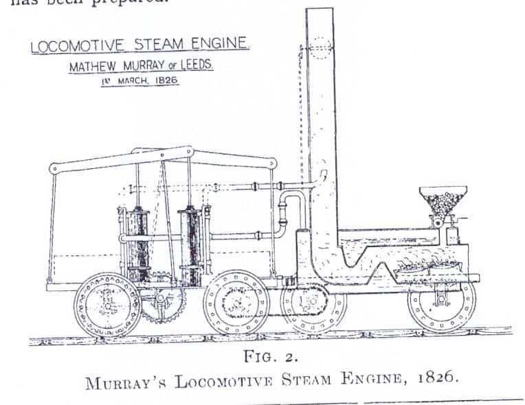 |
There is no record of this locomotive in the patent files, and probably no
such locomotive was ever built. From a photostat of the original illustration,
Fig. 2 has been preparad. Observe not only the blast-pipe and its flexible
connections, but an articulated locomotive, with geared drive, with pulverised
fuel, hopper fed ; the self-trimming grate and the damper control arranged
at the outgoing end of the flues.
In 1828, Nathan Gouch, of Salford, illustrated in a
patent specification, a parallel exhaust pipe located in the centre of the
chimney ol a steam driven road coach. Gouch did not suggest this pipe as
intended to create a draught, however, but only as a means for disposing
of the waste steam ; therefore, in the Author’s opinion, Gouch cannot
rank as a blast-pipe inventor even though it may be that he was the first
to shsw one in a patent specification. In 1829, when Stephenson’s
Rocket won the locomotive competition at Rainhill, the exhaust from
the engine was directed up the chimney to maintain a draught. it is said
that the Rocket arrived at Rainhill, for a preliminary trial and display,
fitted with two exhaust connections at the sides of the chimney entering
in such a manner that no blast effect was produced, and that during the trials
it became apparent to Stephenson that Timothy Hackworth’s locomotive,
which had the exhaust directed up the chimney, was the best steam producer
while running.
Hurried alterations were then made to the Rocket, over-night, and
she ran the official trial with her two exhaust jets turned up the chimney,
each jet having a contracted orifice 1½ inches in diameter. The foregoing
allegation is supported by a footnote in the Minutes of Proceedings, Institution
of Civil Engineers, Volume CXXXIII, page 262, which reads as follols:-
Mr. Edward Woods, Past-President, Inst. C.C., on going to thc Liverpool and
Manchester Railway in 1834, was informed by Mr. John Melling, the Locomotive
Superintendent, that at the time of the Liverpool Competition in 1829, and
in consequence of the great advantage found in the blast-pipe of
Hackworth’s engine, he, before the trial took place, and working almost
night and day, constructed and inserted a regular blast-pipe into the chimney
of the Rocket and thus greatly increased its steaming power.”
It appears that at Shildon, in 1827, Timothy Hackworth, the locomotive
superintendent of the Stockton and Darlington Railway, had actually fitted
a true blast-pipe, with a contracted orifice, to one of the company’s
engines, the Royal George ; but it was not until after the famous
trial had been won by an observant rival, who used an equivalent device,
that the invention became generally known and was referred to as the blast-pipe.
Stated briefly, the Author is of the opinion that William Nicholson invented
the blast-pipe in 1806, that 20 years later Mathew Murray suggested its
application to a locomotile, and that twe1ve months after that, or in 1827,
Timothy Hackworth actually fitted the invention on the Royal
George.
Fig. 4 shows a comparison of Hacknorth’s and Stephenson’s
blast-pipes.
Neither the Royal George nor any other locomotive built during the
next sexeral years, had a chimney shaped to assist a streamline flow of the
gases, despite the fact that Nicholson had pointed the way to this desirable
feature at his first attempt. Early locomotives had a blastpipe carried well
into the chimney, but adjustments to secure better results gradually brought
the blast orifice lower and lower until, by about 1850-60, the orifice was
roughly level with the top row of boiler tubes, or in much the same position
as in many of the engines of to-day.
The air required to be moved by the blast does not all pass through the fire.
Certain volatile hydrocarbons are released as the coal warms up, and these
valuable combustibles would pass away through the flues unburned, if it were
not for a secondary supply of air which is arranged for above the fire.
As early as 1841 special devices were brought into use to act as ducts for
this secondary air supply, such, for instance, as hollow firebox stays, or
open-ended tubes passed through the shokebox, water space and firebox tubeplate,
to deliver air, which had been pre-heated by smokebox gases at suitable points
abwe the lelel of the fire. In some cases the air was forced in by steam
jets, so that its higher velocity might assist in making a more intimate
mixture of hydrocarbons and air, to promote complete combustion. Not much
is heard of these devices today, perhaps they were introduced before their
time, or it may be that, at the period of their testing coal was too cheap
to bother about; but, whatever the reason for the delay, the question of
their utility is not yet settled, because a recent engine of note has a
pre-heated air supply arranged for. Speaking generally, however, on a modern
locomotive the supply of secondary air is taken in at the firehole. It is
evident that in about 1860 the question of draught efficiency received a
lot of attention. The inclined brick arch in the firebox and the deflector
plate in the firehole were introduced at that time, and chimneys resembling
an inverted cone, or having a belled entrance below the. waist were tried,
sometimes in association with multiple petticoats extending well into the
smokebox and designed to distribute the effects of the blast over the whole
tube area. At about this time also, the ring blower was introduced to maintain
the draught when exhaust steam was not available for the purpose.
Proportions for blast-pipes and chimneys are often arrived at experimentally,
to suit the requirements of a given locomotive, and many such experiments
have been made; but, except when all the steam raising factors have been
allowed for, very probably the result has been a thermal loss due to too
much draught.
Draught efficiency is ordinarily measured only by the degree of vacuum intensity
in the smokebox, but, of course, the weight of steam raised per pound of
fuel, to nieet the varying demands made on the engine, is the real efficiency
measure for the draught.
Present Objective.
The object of this Paper is to review the published findings of many of the
experimenters, to place on record any factors which influence the raising
of steam and are susceptible of draught variation, and also to adalyse in
detail each identified factor and its incidence on draught maintenhance Due
to the interdependence of the several parts of the draught apparatus, there
was some overlapping or blending of their functions, but the subject was
reviewed under the following main headings:
Ashpans and dampers.
Ashpans should be deep enough to permit ready access of air to the
whole grate, otherwise an even fire cannot be maintained. It is sometimes
necessary to prevent the passage of air to the underside of the grate, hence
ashpans are made practically airtight and fitted with dampers under the conrol
of the operator. By opening the leading and closing the trailing damper the
draught through the fire can be increased to the extent of the air pressure
at the leading end, which is due to the movement of the engine; or, on the
contrary, the draught can be eased by using only the trailing damper. A damper
opening 25%. of the grate area has been suggested as desirable, but many
locomotives have only about 12% provided, and Stroudley considered just under
7% sufficient. A 12% damper opening, serving a grate having air openings
provided which amount to 30% of the grate area, will produce rarefaction
in the ash pan to the extent of 0.3 inches of water, if the pressure difference
above and below a 12-inch fire on the grate is to be 4 inches of
water.
The movement of air.
Figure 8 showed the weight, volume,. and ve1ocity per period of
atmospheric air when impelled by any pressure difference up to about I7 inches
of water pressure. The graph covers the normal temperature range, 32°
to 92°F.; the velocity of flow at any other temperature, or pressure
difference in inches of water can be calculated by using the formula given
on the graph.
Air openings through the grate.
British locomotives have openings through the grate, for the passage
of air, amounting to about 30% of the grate area. French practice includes,
in some cases, air spaces amounting to about 45%. In America, some grates
are provided with only about 25%., while others have about 40% open. The
class of fuel used may, to some extent, account for these differences in
grate construction; but, other things being equal, theoretically the resistance
offered to the pas-
Noted that specific heat values for for coal had stil to be defined
authoritatively. A high tempertuare in the firebox is essential as this is
where 40% of the heat is taken up. The temperature at the entrance to the
tubes should be 2190F but is only 1800F. The ignition temperature of coal
is 700-925F. Jumper blast pipe mentioned on page 416. Notes Committee of
Railway Master Mechanics Association on Handling the gases of combustion.
7lb of steam is produced from 1lb of coal
Cited University of Illinois
Bulletins Nos 82 and 101. When
considering forced draught he considered the
Gresley paper on three-cylinder
high pressure locomotives presented to the Institution of Mechanical
Engineers noting fluctuations in smokebox vacuum. Noted that experiments
had been conducted in the USA "about thirty years before" on blastpipes and
chimneys.
Page 427: Reproduced letter from Davies Giddy
to William Nicholson in London on the effect of exhaust steam through the
chimney on the fire on Trevithick's locomotive. This letter was published
in J. nat. Philos. Chem. Arts, 1805, Sept.
Discussion:
D.W. Sanford (428-9) noted that a front damper caused
the draught under the grate to be increased, whereas a back damper tended
to impair the draught; and questionned whether use of the front damper, and
if this creates too much draught, then to bore out the blast-pipe and reduce
the back pressure on the pistons? Why is it that on certain lines the practice
of running the back damper is adopted? Regarding the chart showing the
temperature of the gas entering the tubes and the temperature of the gas
leaving the tubes at the other end, he questionned whether they were calculated
temperatures, or whetncr they were observed by some form of pyrometer? McDermid
noted that they were calculated. Sanford asked if according Lawford Fry's
formula? and then made observations on the proportion of the chimney diameter
to the blast-pipe: if we take the figure of 24½ pounds of products of
combustion, to one pound of coal burnt, and if we assume the ordinary
temperatures for the gases and steam coming away from the cylinders, he
considered that the area of the chimney should be roughly nine times the
area of the blast-pipe, irrespective of the quantity of steam which is passing
up the blast-pipe — that is to say, whether the engine is working heavily
or lightly — and that means to say that the diameter of the chimney,
in their experience, had to be roughly three times the diameter of the
blast-pipe. He wondered whether the Author agreed with those proportions,
which were found satisfactory There is a rule given later on proportioning
blast-pipe diameter on the grate area. The rather curious thing is that we
have got chimneys and blast-pipes of the same diameter, some of them on main
line engines which may be doing anything up to 1,200 horse-power, and we
have got the same size chimney and blast-pipe on little shunting engines
which probably never do more than about 400 horse-power, and they work quite
satisfactorily in both cases, though I admit that on the bigger engines everybody
would like to get a bigger chimney if possible.
Sanford described a "rather interesting case a little time back" where
they linered down the cylinders of an engine, for a special experiment, so
that the cylinder volume was reduced to almost exactly half what it had been
before the liners were put in, and they had sufficient confidence in their
ideas about blastpipes and chimneys to do nothing whatever to the blastpipe
or the chimney-that is to say, this engine, which was made half its original
capacity, went out with the same blast-pipe and chimney, and it steamed perfectly
satisfactorily, which seems to show that the blast-pipe orifice has nothing
to do with the size of the cylinder, and seems to depend on the size of the
chimney. As regards the method of fixing the relative position of the chimney
and blast-pipe orifice, one quite satisfactory method is to draw lines from
the inside bore of the blast-pipe orifice to the inside of the chimney at
the top, and so arrange the relative positions that the angle between these
two lines has a definite value.
That is one method of fixing the relative position, and that is what
stops you getting a big enough chimney, because if you want to get a big
chimney, it means that your blastpipe cap, to keep the correct angle, gets
so low that it would be buried in ashes, I wonder whether the Author agrees
with this method of keeping the angle constant, and what angle, in his
experience, is the best. If, of course, we could get a bigger chimney we
should turn out the products of combustion at a lower velocity, and therefore
saye some of the kinetic energy which we now throwaway.
Sanford on main line engines you may throwaway 50 or 60 horse-power in kinetic energy, which means quite a lot going to waste. I wonder whether the Author will teII us his opinion of a very ingenious device which is being used in Belgium just now—that is, the double chimney and the double blast-pipe, because if you cannot get one big chimney you can get the same thing by putting in two little ones, stilI keeping the same angle and the same ratio between each individual blast-pipe and its individual chimney, under 'which, of course, it is correctly set. Another old friend which was at one time thought a lot of is the Adams vortex. There again you increase the outside diameter of a blastpipe cap by putting up an annular space in the middle, which would enable you to get a bigger chimney, and you cou1d also increase the area of the jet and alIow it to entrain some more gases up the middle and the outside surface. Can the Author tell us why this type, which was so highly thought of at one time, has now fallen out of use? Is it because with the bigger engines you have not got room to put the air passages in?
In reply to Sanford, McDermid did not know, but had been told, that if one leaves the front damper wide open travelling at speed one will get large holes through the fire, and that explains why so many locomotive operators prefer to use the back damper. In America, for instance, where sometimes there is a lot of snow they have to depend on the back damper otherwise they may get the ashpan full of snow. With regard to proportions of blast-pipe and chimney it seemed to McDermid that these two items must naturally be correlated in the matter of areas of opening. Acting together, they form a jet instrument the parts of which must necessarily be made to some relative proportion and be placed at a distance apart conforming with some law, not yet defined. With regard to the angle made by the steam jet, he had had no personal experience. Mr. Gresley, however, when discussing the matter some years ago, told him that he thought Mr. Hughes made some experiments with a window in the front of the smokebox, and he found that the natural angle of the steam jet was a cone tapering about one in six. That statement is more or less confirmed by illustrations seen recently in Professor Goss's books. The steam jet appears to be merely an inverted cone with a taper of about one in six on the diameter. What the angle is in degrees he did not know. Mr. Sanford, and others, mentioned the Adams vortex blast-pipe: he considered the Adams blast-pipe was also an ash ejector. More recent example of much the same sort of thing, included 'Stone's blast-pipe, in which a petticoat around the blast-pipe came down to near the bottom of the smokebox and cleared the ash out by blast action.
H. Chambers (429-30): noted Sanford's mention of the Adams type Vortex blast-pipe, . My recollection of that blast-pipe is that there were two side openings provided low down on the blast-pipe by means of which the lower boiler tubes would get a fair share of draught, and then give, a uniform draught over the whole tube area. With regard to the vanous types of blast-pIpes that have be used with varying success, I remember on the old London-Tilbury engines there was provided in the blast-pipe orifice a double inverted cone which was hollow. That cone was filled with common salt. The position of the cone controlled by means of a centre spindle which ran down through the bottom of the blast-pipe, and was connected through a bell crank to the reversing shaft and was therefore automatically controlled by the notch position so arranged that the best orifice was provided for steaming purposes. That, I may say, has been long defunct, and the normal type of blast-pipe cap is now used. I also remember those years ago a driver never went out without a bucket hanging or wire to fit across the blast-pipe cap to improve steaming. That, of course, was not recognised officially, but it is interesting bearing in mind that the Author mentioned the provision of a bar which had the effect of cutting the blast and increasing the periphery for engaging with the products of combustion passing into the chimney. It must be remembered, however, that any alteration made to sharpening the blast may, if other factors are neglected, adversely affect the coal consumption.
There is one point with regard to chimneys in which I have been very interested, and I think all will appreciated when I mention that on the various railway companies' locomotives the position of the chimney with relation to the smokebox tube plate varies very considerably. My expereience has been that it is desirable to keep the chimney and the blast-pipe position well back. When I. say well back, I mean within the limits allowed by the design of the modern locomotive smokebox. The theory I have always had in mind is that the products of combustion escape from .the tubes at a very high velocity and they pass by the blast-pipe before they are fully under the influence of the escaping blast of steam up the chimney and thereby the sparks which are carried forward strike the front of the smokebox door and drop into the bottom of the smokebox and in effect is a very efficient spark arrestor. On the other hand, locomotives in many cases have the chimney fitted well forward from the smokebox tube-plate. I would hke to ask the Author whether in the course of his investigations he has found any marked influence on the efficient steaming of the engine.
H. Holcroft (431-3): Like many others, I have looked forward to hearing this Paper very much indeed. The blast-pipe and chimney together form one of the most important parts the locomotive, which comprises two distinct units — the boiler, complete with the smokebox, ashpan, and so on, and the engine part with the cylinders, motion, frames and wheels. There is no connection whatever between these two units, except the jet of steam which escapes from the cylinders, through the blast pipe, and that is the one connection between the two that makes the locomotive a single unit and everything depends on the efficiency of the apparatus through which that exhaust jet passes. For intance, an engine may have a very high tractive effort, but unless the boiler generates enough steam it cannot sustain a high tractive effort when running. On the other hand, if there is plenty of steam, it may be that through excessive back pressure the locomotive cannot develop its full horse-power, due to choking by a restricted blast-pipe orifice to get the necessary draughts.
With regard to ash pan and damper openings, Mr. Sanford called attention to the question of the use of front and back dampers, the idea being..that when the front dampers open an inrush of air is obtained which assists in the draught. I have tried on many occasions, with different locomotives, the effect of changing from front to back opening while running, and vice versa, but have never detected the slightest influence on the draught; as far as I can see, it does not make any difference at all. On the other hand, when running through a tunnel or a long, low bridge with only a small regulator opening it often happens that a sudden tongue of flame shoots out of the fire-hole, simply because the air is confined and there is no lateral spread of the air under the engine; it cannot get away, with the result that a sudden increase of pressure occurs in front of the ashpan and the air rushes in; but apparently in the ordinary course of running the air is dragged along with the locomotive, or projected out sideways, so that this increase of pressure that the Author rather relies on does not materialise in practice. .
Regarding air openings through the grate and fuel bed, Holcroft observed during one of the coal strikes when American coal of rather lower calorific value than the ordinary English was used, that the steaming was nevertheless very good. The reason attributed to this was that the screened coal was of more or less uniform size; hence the openings through the fuel were regular, and very much nearer to the ideal conditions for combustion. With a screened coal about the size road metal, combustion seems very efficient.
Holcroft's experience indicated that locomotives with oval or approximately oblong firehole doors are much better steamers than those with round openigs: with round fireholes and half-round deflectors there is a much greater bunching of cold air, which reaches the tubes in the middle of the tube plate. In the case of a wider and less deep opening with a more less level top the air gets spread out better. A device which firemen can often make a shy steaming engine steam well, is that of putting a piece of plate across the lower part of a round fire-hole and firing over the top of it. Apparently the air, in striking the sharp edge of the plate, is deflect downwards on to the fire instead of going direct towards the tube plate.
The position of the chimney on the smokebox had been referred to by Mr. Chambers, but it has been Holcroft's experience that it is better to situate the chimney well forward, because it brings about a better distribution the draught over the front tube plate and the gases do not have to take such an abrupt turn to reach the vertical. On the question of nibs, bars, corrugations, etc., near the blast-pipe orifice, to produce eddying and so entrain more gas, it is doubtful whether this is really anadvantageous because the result is to increase the contact area of the steam with the solid surfaces, and so reduce its velocity. Also there is the question of the carbonisation of the blast-pipe which becomes furred up with carbon deposit in a very short time, and this collects under any projections in the orifice: that was one of the reasons for the Adams vortex pipe being abandoned — the difficulty of removing the carbon deposit from the narrow annular orifice.
As regards the action of the exhaust steam in producing draught, nobody seems to have come to a definite conclusion as to what really takes place, but apparently several actions occur; there is a certain amount of ejector action due to surface contact of high velocity steam with .the gases, a small amount of entraining of the gases, and to some extent, perhaps, a piston-like action of plugs of steam in the chimney with each exhaust beat which sandwich the gases between them; and so it seems to be a mixture of those three in varying proportions. Another thing about the blast-pipe is that it is always assumed that the steam comes out of the blast orifice at equal pressure all over, but I was very much struck when travelling on the leading engine of a pair going through a long tunnel on an up-grade, in watching the sparks coming from the chimney of the second engine, which as an old saturated engine with the steam-chest between the cylinders. As the sparks came out they made a different angle of incidence with the sloping tunnel roof with each of the four beats in a perfectly rhythmical manner, showing hat the direction of the steam and gases took a slight change with each beat, and I put that down to the fact that possibly the direction from which the steam came from he cylinders made a difference. Perhaps through being a saturated engine a certain amount of moisture came up with the steam, and was projected to one side, and it evaporated at or near the blast-pipe orifice where pressure changed to velocity, so that there was a difference of density n the blast-pipe orifice itself which deflected the jet slightly. That may be an explanation as to why an engine with its valves badly out of beat is often a bad steamer, because the effect of the blast is more pronounced in one direction than another, and thus have the same effect as if the chimney and blast pipe were out of line.
Colonel Kitson Clark: (433-4) I have not very much to add, except one or two historical points. One is the story about he blast-pipe in the Rocket. I believe that the father of our friend Sir John Dewrance also worked on that blast-pipe.He might, as there was a record passed to Sir John many years ago as to his father's connection with the story. With regard to what Mr. Holcroft said about the oval fire-hole door, I had the privilege of riding on the top of the boiler of an Atlantic type locomotive that ran from Philaelphia to Atlantic City in 1897. The firebox, as far as I remember, was styled Wootten. It had two fireholes, and the coal was exactly what has been described-picked pieces, rather smaller than one's fist, over the whole of the grate area, and they practically did not add any fuel during any time of the run of 47½ miles. The, engine steamed extra~ordiriarily well, and perhaps rather from its own merits than my approving presence, made history. With regard to the Author's fine series of data, I find myself rather saturated with statistics, indeed more than I can digest until given more time; but I think there is something further which deserves investigation and even meditation, and that is what might be called the mechanico-physics.Mr. Chambers raised an interesting point about the - position of the chimney. He is quite right, if the chimney is well back, sparks go into the front end of the smokebox and die before they go through the chimney, but so far as the position of the chimney is concerned in the matter of forming a draught, I cannot conceive that its location makes ny difference at all except as Mr. Holcroft has said, the gases take an easier bend to the exit when the chimney is laced well forward. One may regard a smokebox as a chamber which is exhausted by the action of the blast, and though I.do not pretend to speak with any authority on it the subject, I think that most of the troubles are really due to too much draught. For instance, Mr. Carling was talking about a 50 per cent. improvement effected by altering the blast, one wondered what the draught arrangement was before the alteration.
Mr. WiIIiams mentioned the Garratt locomotive. I would like to ask him this, just by way of collected iriformation. In the Garratt locomotive there is one very long blast connection and one short one. Is there any noticeable difference in the fire, due to the reservoir capacity - in the long blast-pipe? It would appear that there must be a cushioning of the blast, which should give all the gentle draught advantages of, for instance, the Kylala blast pipe, which, owing to a large exhaust opening, gives a more a gentle jet effect. The figures which I have put before all tend to prove that a gentle zephyr through the fire gives the best and most economical results.
With regard to the position of the fire-hole in relation to the deflector, plate and the shape of the firehole Mr. Holcroft mentioned the fireman's trick of blocking the lower half of the fire-hole to secure better steaming. The fireman's device made a more effective deflector' plate, and this means that he drove air straight down on to the fire, which is just what is wanted. Drive the air entering the fire-hole straight down on to the fire it will get hot and thus improve the temperature of the firebox. Keep up the temperature of the firebox and you will get good results.
Mr. Carling said that the blast-pipe on a certain locomotive was altered to advantage, but he did not say whether they increased the draught or reduced it. - May I ask whether you increased the draught or reduced it? Mr. D. R. Carling: I have only got down the evaporation figures on my notes. I think, however, that the
D. Kitson Clark (433-4) referred to the blastpipe and draughting
arrangements for the Kitson-Still locomotive. D.R. Carling
(434-6) noted that one of a highly successful series of 2-8-2s built
for the Missouri Pacific Railroad had been rebuilt as a three-cylinder
locomotive. This locomotive was tested by the Pennsylvania Railroad at Altoona
and modifications made to the blastpipe enabled an increase in the maximum
evapourative rate from 48,000 lbs/h to in excess of 60,000 lbs/h and this
emphasised the potential available through improved draughting. He added
that Duplex chimneys require further examination. Cited Ulrich Barake:
Rechernische Untersuchung der Warmeuberttragung im Lokomotiv-Langkessel.
Author (page 436) noted that Hughes experimented with a window into the smokebox
and discovered that the steam jet from the cone tapered at about 1 in 6 and
this is similar to that stated in Goss's books. He noted that the Adams'
Vortex was also an ash ejector as was Stone's device. He asked Williams if
the distance from the firebox affected draughting on Garratt locomotives.
Seventh Ordinary General Meeting of the North Eastern Centre (Session
1931-32) held in the Hotel Metropole, Leeds on Friday 8 April 1932 at
7.15 p.m.: chair taken by T.H. Sanders, Chairman.
Saunders (439) noted that the Vortex and Maclellan variable blastpipes had
been used on the GER. (in response McDermid noted that the Maclellan blastpipe
had been standard on the GER for a time. W.E. Selby (439-40) was informed
by McDermid that the space between the firebars should be as large as possible.
J. Blundell (441-2) stated that the GCR had evaluated Hill's grate in which
steam was blown through the ashpan, but it was not very successful. Blundell
also returned to Gresley paper on
three-cylinder high pressure locomotives to consider what was happening
in the smokebox. O. Becker (444-5) mentioned a considerable body of work
on the subject: in 1894 in Hanover there were experiments on nozzles, distances
and cylinder pressures; in 1901 the Master Mechanics' Association sponsored
experiments on stacks at Purdue University under Professor Goss; and there
were tests performed at St. Louis for the Pennsylvania Railroad. Sheridan
(445-6) noted that larger grate areas were common in Belgiium.
Brazener, W.F. (Paper 293)
The manufacture of copper firebox plates. 447-74. Disc.: 474-500: 1934,
24, 128-41.
Eighth Ordinary General Meeting of the Session 1931-32 held in the
hall of the Institution of Mechanical Engineers, Storey's Gate, Westminster
on Thursdav 21 April 1932 at 6.0 p.m. with chair taken by W.A. Lelean,
President-Elect.
Outlines principal properties of copper. Chronicles use of copper in the
manufacture of firebox plates. Details production of copper plates, covering:
casting, or ingots. The chief cause of trouble in a firebox is due to the
wastage of stay heads and the portions of the copper plate near to the stay
heads on account of corrosion. This is found to be due to very small leakages
which occur when the firebox is cooled down, between the threads of the stay
rod and plate. The immediate effect of this is to remove the protective scale
on the stay head and the adjoining part of the plate. It is felt, therefore,
that if some method can be employed for producing a perfectly water-tight
seal at the stay head, the main cause of the trouble will be overcome.
Summer meeting, 23rd and 24th June, 1932. 501-4.
Due to the financial situation the usual bi-annual Summer Meeting
on the Continent was replaced by a two-day visit to Doncaster, Sheffield
and Derby organized by L.J. Leclair and H.E. Geer. London members, with the
President (W.A. Lelean), travelled on the 10.10 a.m. King’s Cross to
Doncaster in reserved compartments. On arrival they were met by R.A. Thom,
Mechanical Engineer (Doncaster), F.H. Eggleshaw, Locomotive Works Manager,
and W.H. Brown, Carriage and Wagon Works Manager, and under their guidance
were shown round the Locomotive and Carriage Works. On leaving the locomotive
shops the members were photographed (reproduccd) in front of one or the 2-8-0
three-cylinder goods locomotives incorrect: Gresley Pacific with corridor
tender). On view in the yard was one 0-8-4 tank engines recently fitted with
a reversible booster. The next visit was to Metropolitan-Vickers Electrical
Co.'s Attercliffe Works at Sheffield, and members travelled on the 17.24
to Sheffield. Having deposited their bags at the Victoria Hotel they proceeded
by motor coach to the Attercliffe Works. Here, under the guidance of G.H.
Fletcher, Works Chief Engineer and Manager, Carson Dodd from Manchester,
and A. Hodson and J. White, they inspected three Diesel-electric locomotives
under construction for the Ford Car Company's Dagenham Works. The engineering
and design of these locomotives was carried out by the Traction (Loco.) Staff
of the Metropolitan-Vickers Electrical Co. at Trafford Park, under the direction
of Carson Dodd, and the construction and erection of some under their
supervision.The electrical equipment was manufactured at the British Thomas
Houston's Works at Rugby and the engines by W.H. Allen's at Bedford. At dinner
in the Victoria Hotel the chair was taken by the President, W.A. Lelean,
and the guest of honour was R.A. Thom. In reply to the President Thom referred
to the extensive reorganisation which had been undertaken at Doncaster, and
the whole-hearted and loyal support he had received from his assistants.
On 24 June members travelled by motor coach to Derby by a scenic route, then
lunched at the LMS Hotel before visiting the Rolls Royce Works, under the
guidance of Wormald, the General Manager, where an enjoyable and most
interesting afternoon was spent, Thence by motor coach to the LMS Station
at Derby.
Visit of Birmingham Centre to the Sentinel Wagon Works, Shrewsbury, June
1st, 1932. 505.
Group photograph with key: D. Carling and R.G. Jarvis were amongst
the group of 33.
Meeting in Birmingham, 11th November, 1931. 507-8.
The Second Ordinary General Meeting of the Birmingham Centre, Session
1931-32, was held at the Queen’s Hotel, Birmingham, on 11 November 1931,
at 6.45 p.m., the chair being taken by Mr. R.G. McLaughlin. The Chairman
then introduced Mr. C.C. Cowling, who read a Paper, entitled Location and
Acquisition of Natural Water Reserves, and this was the subject of a discussion.
("This Paper is available at Head Offices to any member wishing to read it":
it is not in the electronic database.)
Meeting in Birmingham, 9th December, 1931.
The Third Ormdinary General Meeting of the Birmingham Centre, Session
1931-32, was held at the Queen’s Hotel, Birmingham, on the 9th December,
1931, at 6.45 p.m., and the chair was taken by Mr. R.G. McLaughlin. The Chairman
introduced Mr. G.H. Willett, who read a Paper, entitled Wrought Iron and
Steel Tubes, and this was the subject of a discussion. ("This Paper is available
at Head Offices to any member wishing to read it": it is not in thw electronic
database.)
Meeting in Birmingham, 20th January, 1932.
The Fourth Ordinary General Meeting of the Birmingham Centre, Session
1931-32, was held at the Queen’s Hotel, Birmingham, on 20 January, 1932,
at 6.45 p.m., and the chair was taken by Mr. R.G. McLaughlin. The Chairman
then introduced Mr. C.G. Miller, who read a Paper, entitled Roads and the
Road roller, and this was the subject of a discussion. ("This Paper is available
at Head Offices to any member wishing to read it.")
Journal No. 109
Pudney, F.A. (Paper No. 292)
Notes on three diesel engine types; Some recent cam gear improvements. 512-33.
Disc.: 534-47.
Sixth Ordinary General Meeting of the 1931-32 Session held in the
hall of the Institution of Mechanical Engineers, Storey's Gate, Westminster,
on Thursday, 25 February 1932, at six o'clock; Mr. W.A. Lelean, Vice-President,
was in the chair.
Included mention of Tosi diesel electric locomotive and Ansaldo direct drive
diesel locomotive. and
The Christiani compressed steam locomotive is essentially the system is one
of a Diesel engine, under governor control, direct-coupled to a three-stage
compressor ; this compressor deals with steam, and not air, such steam having
been previously raised to a low pressure in a small generator by means of
normal oil fucl burner. The low-pressure steam is compressed and in effect
passed to a high-prcssure storage tank, from which the supply is fed through
thc usual 1ocomotive cab control regulator to the locomotive cylinders, which
in the case of the locomotive illustrated in the slides is of two-cylinder
outside type. The evhaust steam is in turn discharged to the lowpressurc
storage system. thus resulting in a closed circuit operation.
The Diesel Electric under review was constructed by Franco Tosi S.A., in
co-operation with the Italian State Railways. There were no batteries, and
no attempt was made to use special components, in fact, the design deliberately
provided for the adoption of existing Diesel plant and electric equipmcnts,
etc. The Government programme provided lor threc types: (a) light rail cars
to 150 h.p. fitted with gearbox ; (6) Diesel electric locomotive to 500 h.p.
for secondary lines, and standard gauge, two of these being constructed to
designs by Franco Tosi S.A. and the Fiat Co., the latter unit arranged for
metre gauge operation ; the Franco Tosi being herewith described ; and (c)
the Ansaldo direct-coupled Diesel locomotive, described later, 1,000 h.p.
Ansaldo Direct-Drive Diesel Locomotive, illustrated in Figs. 4 and 5 and
is not a travelling electric power station, but an attempt to provisde a
unit wholly mechanical in construction, and without gearing or flubd clutches,
or electrical gear of any kind. The scheme provides for main line operation
on standard gauge, and from an examination in the Ansa1do shops the !ocomotiw
leaves a very favourable impression. Unfortlmately, an accident occurred
whilst the locomotive was on test, which had the effect of postponing further
development work with this very promising type of prime mover, coupled also
with the adverse Italian economic conditions. The Author is aware that Ansa1do
have further developed their scheme for direct driving, and are prepared
to negotiate with builders in this Country for a licence to construct to
their design, so that notes will only be a repetition of descriptions which
have appeared in various technical journals.
The Author was for some years in close association with the administrative
technical head of Ansaldo, Engineer Carlini, when it was possible to examine
thc engine in question during the co'urse of its erection. The power unit
is a six-cylinder Junkers Diesel engine operating on the two-stroke cycle.
It is a horizonta! mo,del, and follows stanbdard Junkers practice in that
thc opposed piston principle is utilised, each cylinmder havingtwo pistons
with a common combustion space between theni. There are three lower cylinders
side by, side, and threc similar upper cylinders, each lower cylinder, with
the one
Discussion
W.J. Wakley (534-5): It would seem that the question
of the Diesel engine for railway work is at once tied up with the form of
transmission which is employed. In dealing with the last example which we
were given of the direct-drive Diesel, the first point which would occur
to some people is whether or not that vehicle would be satisfactory on continual
shunting operations, that is to say, whether the accumulators could be kept
sufficiently charged to maintain the locomotive in service for continual
shunting work.
It is rather surprising to learn that at such a low crankshaft speed as 10
r.p.m. on the Diesel side the vehicle is capable of performing useful work,
and I am rather wondering whether that is quite true, or whether the compressed
air is definitely assisting at this speed in some considerable way.
One wonders whether the examples shown to us to-night are examples which
in existing conditions one can continup with, and whether possibly it might
not be more advantageous generally if one were to tackle the proposition
from the other end with lower horse-powers and work up. In only one case
has the question of gear drive been referred to, but I do not think we have
particulars of what form that takes. My experience of the design of internal
combustion railway vehicles has been confined entirely to gear drives, and
I have found that once the difficulty has been got over of starting the load,
the gear drive is perfectly satisfactory, providing that when it is necessary
to change from a low to a higher gear, or vice versa, the gears are such
as one can manmuvre. My recent experience has been in connection with a multiple
speed gear box where we have arrangcd the maximum overall reduction as high
as 40 to I , and in those cases we have experienced no difficulty at all
in starting the load and in changing the gear and maintaining vcry high average
speed and very rapid acceleration.
There is a reference in the Paper to the fluid fly-wheel. This wheel would
appear to be necessary only as a means of getting away with the load when
the maximum torque available from the internal combustion engine cannot be
obtained at low road speeds, but if you reduce your maximum overall ratio
there is no difficulty at all in starting the load and excessive clutch slip
does not take place. The whole question really, except, of course, in the
very heavy locomotives, is one of h.p. weight ratio, and, generally speaking,
with a gear-driven internal combustion locomotive or rail car of up to 300
h.p. we have been able to get down the weight to a ratio of from three to
five h.p. per ton, which is fairly satisfactory, and gives satisfactory
acceleration. Generally, with a 300 h.p. locomotive we are able to haul maximum
loads of go tons at speeds up to 50 miles an hour. In regard to gear
transmission, it will be found, generany, that the weight of the gear
transmission is less than the weight of electric transmission, and again
I think, generally speaking, the price is lower. I should like to hear from
the Author in answer to the point I raised about the starting of the Diesel
engine in the last example he showed us.
J.W. Hobson: (554-6) It is probably very fitting
that I should be called upon to open the discussion on this important subject
seeing that my firm, Messrs. R. & W. Hawthorn, Leslie & Co., Ltd.,
have .been so extensively concerned in the pioneer experimental work which
proved so necessary. The experience of my firm in connection with the de-
1 elopment of the internal combustion locomotive dates from 1910, when enquiries
for such types were received) from abroad, and the difficulties of the
application of the internal combustion engine for railway traction purposes
appeared almost unsurmountable.
The first constructive effort was made during WW1, when small internal combustion
locomotives which we supplied rendered such a good account of themselves
as to afford us such encouragement to pursue our investigations and carry
out a variety od experiments concerning the development of this type in larger
powers.
As regards the Power itself the Author has dealt with the various types in
such an open manner that I find myself in almost complete agreement with
him and my remarks will therefore be complementary rather than critical.
Immediately after the War, in view of the varied demands, it was necessary
to make a complete investigation into the possibfle uses of a variety of
fuels, but for the larger powers the heavy oil engine was the only one worthy
of real consideration.
In this sphere we were more fortunately placed than were other locomotive
builders in this Country, being a composite firm, and our marine department
having developed a successful marine Diesel engine-but still the handicap
was great, as it was impossible to1 obtain a heavy ail engine light enuugh,
and of sufficiently high speed to suit the demands of railway traction.
The question of the most suitable transmission system was also embarrassing-and
the many advantages of the electrical was at that period counterbalanced
by its excessive weight and cost.
It was foreseen that the direct driven heavy oil locomotive was the ideal,
and it is interesting to note from the Paper the present position as regards
the development of this type.
Messrs. SuIzer Bros. were of course the first, to experiment with the direcq
Diesel type which also embodied compressed air starting. These experiments
extended over the years 1907-12, and a great trouble appeared to be the number
of broken crankshafts and altogether the locomotive did not achieve the results
anticipated. We have had experience with two of the classes referred to by
the Author and in addition have also been concerned with hydraulic and mechanical
transmission systems.
The Author has described, the Cristiani type very thoroughly and it is gratifying
to know that Hawthorn, Leslie carried out the preliminary experiments of
this system. This was done by converting a standard 14-inch six wheeled coupled
locomotive and even then an overall efficiency of 13i per cent. was obtained
when developing approximately 300 h.p., or, in other wo'rds, an efficiency
double that of the orthodox steam lcxomotive. An important result of these
experiments was the discovery of the necessity of providing reasonable heat
storage capacity for starting purposes and meeting peak load conditions.
These trials were considered so satisfactory that the further developments
described by the Author were proceeded with on the continent, and the results
he gives certainly justify his contentions that this system of transmission
is worthy of the close attention of the steam engineer. In the Kitson-Still
engine andl also in the Cristiani system we find a method of marrying the
internal combustion and the steam cycles. In the case of the former this
calmbination is effected in the polwer cylinders and in the latter in the
system as a whole, and from the metallurgical point of view the latter is
no doubt preferable.
It will also be observed, that in the case of the Cristiani system the
power-weight ratio1 is encouraging and in adklition the controll is wonderfully
elastic, possessing many of the features of electrical transmission.
With reference to the other system described by the Authorr with which we
have had experience, viz., the oil-electric, it must be stated that our
experiments in 1922-4 proved conclusively that lighter electrical machinery
was practicable-the control was most satisfactory, and the overall transmission
efficiency including the worm drives on the axles was 82 per cent. This
locomotive was 320 h.p. with a draw bar pull of 6 tons and incidentally was
the first to have the power of the traction motors transmitted to the axles
through worm drives, which considerably assisted in the solution of various
problems including the reduction of weight.
It may reasonably be asked why the internal combustion locomotive should
not have been more extensively adopted after so much experimental work has
been carried out. The Author has explained that this is largely question
of finance, and that although the various types he describes have all given
great promise of success, a certain amount of further development and'
demonstration is necessary to fully convince engineers already sympathetic
to their adoption. It has also to be borne in mind that coal is the natural
fuel of this Country, and until such times as oil-fuel can he commercially
produced from coal, the probable spheres of activity of the internal combustion
locomotive are limited to certain industrial undertakings and secondary main-line
service. Furthermore, the higher initial cost of this class of motive-power
as compared with the steam locomotive is viewed with apprehension by the
responsible financial authorities.
The position in certain areas abroad is, however, altogether different, depending
upon the class of fuel available and the nature or non-existence of feed
water. With reference to rotary cam gear on steam locomotives, I certainly
think the adoption of poppet valves is a step in the right direction as they
obviate the difficulties of lubrication consequent on the use of high superheat,
but as regards their operation my experience has been confined to Lentz drives.
C.J.H. Trutch (543-5) While we are very greatly
indebted to the Author for having brought forward these admittedly experimental
locomotives for discussion, I hope very sincerely that locomotive engineers
will not judge Diesel perfection by the types which he has described. The
Ansaldo and the Cristiani are interesting experiments, and the Tosi electric
was an early trial now left far behind by the perfected Diesel electric
locomotive.
Reference is made to the Ansaldo as a directdrive type:; it is so to a certain
extent, but I think it should be realised that both the Ansaldo and the earlier
Sulzer (built in 1912) depend very much on the air compressor for starting,
and if you take that into account and consider also the other compressor
types, whether compressed steam or compressed air, you will find that you
have, to all intents and purposes introduced three engines in place of one.
First you have the Diesel engine itself, then you have the compressor, and
then you have the means of using the compressed medium for driving the wheels.
In the case of the Ansaldo that means it is the motion gear which is required
to get the motion from the horizontal engine to the driving crank axles.
Why should one have this complication when, with an electrical transmission,
the thing can be done with simple rotary motion, involving a minimum of moving
parts and bearings ? One of the chief disadvantages of the Cristiani system
is that it does not get rid of the boiler and its attendant troubles,
which are really the chief difficulties encountered in steam locomotive maintance
and running. Another example of that is the Kitson-Still locomotive, where
the manufacturers admit that the fuel consumption of the oil firing of: the
boiler is so great that it cancels the high efficiency of the Diesel engine
itself, and the bulk of the difficulties experienced appear to be associated
with the boiler.
Presumably one object of a direct drive on a Diesel engine is to get a lighter
and simpler unit. As regards weight, it may be of interest to say that we
are now building Diesel locomotives with electric transmission, which will
compare in lightness with any of the figures which have been given for the
direct drive, and compressed gas drives ; that is to say we can build a
locomotive which is as light as it can be, having regard to the running
requirements, i e . , adhesion and stability of running. I would like to
emphasise that point, that the electrical transmission is not unduly heavy
and not unduly expensive, when properly designed. I think in the earlier
examples both the weight and the cost were badly overdone, due to certain
difficulties which can be, and are being, now overcome, and, as Mr. Tritton
remarked, due to the electrical manufacturer being given too free a hand.
A previous speaker has mentioned the gear drive, and the same remarks apply
to that, except in the smallest sizes. There is very little difference between
the weight of a properly designed electrical transmisson and a gear drive,
in the larger sizes, and I think it is generally recognised that there has
so far been no success with gear transmission in the bigger sizes. In the
smaller sizes it has worked satisfactorily, but the deciding factor here
is the effect of the maintenance cost and the life on the economic balance.
Reports of the American Railway Association show that the life of both engine
and transmission using electrio is double that with gear drive, the maintenance
cost is halved, and reliability increased.
I hope that locomotive engineers will not go away with the impression that
the Liverpool Tramway bogie shown in a slide is a typical electrical transmission
arrangement. It is, indeed, a very complicated arrangement which was introduced
in order to get a flexible connection between the axle and the motor. It
is only necessary in railway work for really high-speed running, and, in
any case, far simpler flexible connections have been designed and are running
satisfactorily in large numbers on heavy electric locomotives. The reason
I make that remark is that the criticism which one hears frequently made
with regard to electric transmission has largely arisen from the mass of
unnecessary gear piled on to most of the early experimental types. Everybody
is looking for the flexible engine which would enable one to get direct drive,
but I think one must admit that that is very much in the distant future,
though it will no doubt come in time. In the meantime, we have ta-day in
the electrical transmission a known method of transmission of proved reliability,
the maintenance cost of which is also proved to be very low.
It is known on practically every railway system, and is not restricted in
power or locomotive speed. It is the only system applicable to the multiple
unit motor coach set type of train, which has such tremendous possibilities
for economy in all stopping services. We have also highspeed engines for
use with electric transmission which have now reached a reliable stage of
development, and the combination provides possibilities of standardisation
not apparent in any other system. Therefore, is it not good policy for the
railways to go ahead with the Diesel-electric types, getting the economic
advantages which can be obtained from them, and in the meantime continuing
these experiments which may provide an alternative for certain classes of
locomotive in the less immediate future ?
Wade, L.H. and Short (Paper No. 294)
Some aspects of electric tractor design. 563-89. Disc.: 589-99.
Sixth Ordinary General Meeting of the North Eastern Centre (Session
1931-32) held in the Hotel Metropole, Leeds, on Friday, 26 February, 1932,
at 7.15 p.m., the chair being taken by Mr. J. Blundell, Vice- Chairman.
E. Windle (591) requested information about the amount of power consumed
by the auxiliaries by a 2000 hp electric locomotive.
Lewis-Dale, Percy (Paper 295)
The chemist in relation to railway engineering. 599-613. Discussion:
614-19.
Fifth Ordinary General Meeting of the Manchester Centre (Session 1931-32)
held at the Manchester Literary and Philosophical Society, 36, George Street,
Manchester, on Friday, 11 March, 1932 at 7 p.m.; chair taken by S. H.
Whitelegg.
The analysis of coal, water and the effect of water softening chemicals,
lubricants and oil for signal lamps. Goss (618) suggested that the figure
quoted for unburnt fuel exiting the chimney (5-35%) represented United States
conditions and that in Britain this would not exceed 20% with long travel
valves and correct blast pipe and chimney proportions.\author was Chief Chemist
of the LMS (see Paper 648),
Discussion: Lang (614-15) noted that Reddrop at Crewe Works had introduced the elegant bismuthate analytical technique for manganese. He also noted the difference in the environment of Crewe Works as compared with the contract shop (Beyer Peacock) in swhich he had been trained. Other contributors were Gresham, Bond and Gass.
Lelean, W.A.
Presidential Address 1932 (Standardisation). 640-63. Disc.: 663-75.
Items which could be standardised, were boiler mountings and the following
engine details:
Meeting in Manchester, 20th October, 1932: Whitelegg referred to the ratio of adhesive weight to tractive effort, he agreed with the figures quoted by the Author, viz., 4¾ to 1 was "reasonably satisfactory", assuming the standard locomotive is a four-impulse one, but if other standards have six or eight impulses, he would suggest that the ratio is too high and might be considerably lower. He was interested in the President's remarks regarding cast steel bar frames, as it had always been a "matter wonder to him" why this type of frame, which apparently meets with success in America and the Continent of Europe had not been tried in this Country. Of course there are obvious objections of weight and decrease of space betweer the frames, but even these do not appear to be insurmountable. He had read in the technical press that steel castings of this size could not be produced satisfactorily in England on account of the lack of annealing furnaces capable of dealing with them.
H. Chambers (667) observed that one of the great benefits derived from standardisation was that it had made it possible for engines to bc repaired on the belt system, which had resulted in great economies, particularly the reduction of time an engine is out of service for general repairs. In the early days of the formation of the L.M.S. Railway a Co-ordination of Design Committee was set up. As an illustration of the work involved by one item only, it was found that there were about 150 different types o$ taper pins in use, i . e . , varying sizes and tapers. It was finally decided to standardise the taper of all such pins to 1 in 30, and the total number of pins to be stocked which covered all requirements was reduced to 15.
Gass (668-9), referring to the question of maximum tractive effort, remarked that from investigating a large number of indicator starting diagrams he found 82 per cent. to be a safe figure for calculating the maximum available tractive effort. Later experiments confirmed that figure. To standardise the ratio of adhesive weigbt to maximum tractive effort it is essential that some fixed figure for mean effective pressure should be adopted. With regard to adhesive weight, a safe factor to meet all weather conditions is 20 per cent. of the weight on the rails of the driving wheels for two-cylinder locomotives, and 25%. for four-cylinder balanced engines. Spring compensating beams have not found favour in is Country. The Atlantic type engines on the Lancashire & Yorkshire Railway Company were originally equipped with compensating beams, and considerable slipping took place. The slipping was much less pronounced after discarding the compensators. The proportion of grate area to heating surface is important; a good ratio appears to be about 1 in 65, but in large boilers with the firebox between the frames it means an extremely long box which is difficult to fire successfully. The first locomotives built as standard at Horwich comprised a 4-.4-0 passenger, a 2-4-2 tank, and an 0-6-0 oods engine. The boilers, cylinders, and valve motions were practically interchangeable in the three types. Tests carried out with a 0-8-0 engine and a 0-6-0 engine, hauling goods trains to the same timing, the tractive effort of the former was 28,426 Ibs., and the latter 20,383 lbs. When hauling a load of 600 tons the more powerful engine consumed 17 per cent. less coal than its competitor. The economy decreased as the load decreased, and with a 300 ton load the fuel consumption was equal.
J. W. Smith (669) agreed that if one got the
opinion of he Shops, the Sheds, and the Drawing Office together, one would
aim at simplicity, which was the keyword of standardisation. About
the smokebox, he was in favour of everything below the ash level being made
of cast iron, but above that he was not too certain. With regard to joints,
it is necessary to make everything in an engine smokebox so that one could
get it out. He was not so sure that a girder design of frame was right. To
his mind one wanted flexibility. In connection with the omitting of collars
on the journals, he remarked that years ago they had some trouble with tender
axles and the outer collars were turned off. The result was that the frames
bulged outwards. If one takes the collars off one is taking stiffness from
the frames. If one omits collars on the inside the frame goes in and one
gets the weight on the wheel boss. That is one point in locomotive
design—when curing a fault one has to be sure it does not create a
worse.
A, Devon (664) supported the Presi.dent in his remarks
with reference to the bar frame. When the Institution made its visit to Berlin,
he noticed that the German State Railways had adopted a bar frame, and he
took the opportunity of asking Dr. Wagner what their experience of these
frames had been, and was informed that it had been entirely satisfactory;
in fact, that some of the largest locomotives had been off the line in very
serious accidents and that after examination it had been found that the bar
frame had in no case shown any signs of distortion. That would certainly
not have been the case if the frame had been a plate one. There are some
people who consider that the plate frame is desirable because it gives a
certain amount of lateral flexibility. He wondered if that is really desirable,
because, after all, in a machine it seems to be very important that the rubbing
surfaces should be maintained in correct alignment. In order to ensure that,
one would think it would be very desirable to have as stiff a frame as possible;
and there can be no question that of the two frames the bar frame is much
stiffer than the plate frame. Again, in the plate frame there is a great
deal of material used where it is not subjected to the maximum stress which
it can bear ; that is to say, much of the material of a plate frame is not
being used to the maximum efficiency. That criticism cannot be levelled to
the same extent against the bar frame, because the material is undoubtedly
disposed of there in a manner where most of it is brought to give as much
service as possible. Therefore he thought the President was to be supported
in his remarks, and he for one would like to see the bar frame adopted in
this Countryat any rate for locomotivks of the largest type
Meeting in Newcastle on 16 November 1932:
C.N. Goodall (673) remarked some will remember that as long ago as 1860 D.K.
Clark, in the preface to his wellknown work of Railway Locomotives,
called special attention to standardisation, and said that at that time probably
five distinct classes of locomotives would suffice for the varied traffic
of railways, whereas he supposed that there were nearer five hundred in this
Country and elsewhere. He expressed the view that the principle was not only
desirable but practicable and that it was likely to be more wicdely adopted
in the future. Looking at the results achieved during the 70 years or so
which have intervened, one can hardly say that his ideas have been realised.
Those who are acquainted with Indian Railways will, he thought, agree that
they have always been somewhat fortunate in the matter of uniformity in their
locomotive stock. In most of these cases the parts of engines of a like class
were largely interchangeable, and the fact that from first to last some hundreds
were supplied, clearly showed that €or certain classes of traffic certain
classes of engine could be closely standardised and be just as useful on
one railway as another.
Some of these old types did good service in India for something like 40 years,
possibly more, but they were naturally becoming obsolete when nearly 30 years
ago it was decided to establish a series of recognised standard locomotives
for India. This new series has now had a fairly long run and on the whole
has been very successful. There is very little doubt that it has fully justified
the policy of a wider application of the principle of standardisation of
locomotives such as was visualised 70 years ago by D. I(. Clark. Probably
Indian locomotive standardisation is the first instance of its kind on so
comprehensive a scale.
.C. Schlegel (p. 673) stated that standardisation is a thing to aim at, and
so far as a running shed is concerned would effect considerable economy in
the stocks of material kept on hand and which so often come under criticism.
There is very little attempt at standardisation to-day and much more cnuld
be done in this direction, Take a simple example like the big-end and side
rod oil well tops, what a variety of sizes we have, even on engines of about
the same capacity.
Baillie, N.L. (Paper No. 296)
Foundry working on railways. 676-736. Disc.: 737-56.
Second General Meeting of the South American Centre held on Friday,
29 July, at 14.30 in the Hall of the Centre of British Engineering and Transport
Institutions, Sarmiento 1236, Buenos Aires, the chair being occupied by Mr.
F.C. Bown (in the unavoidable absence of Mr. Mayne).