Locomotive Magazine and Railway Carriage
and Wagon Review
Volume 28 (1922)
Key index to all volumes
Number 353 (14 January 1922)
Recent American built locomotives for France and Spain. 1-3. 2
illustrations, 2 diagrams (side elevations)
American Locomotive Company Mikado 2-8-2 type supplied to the Northern
Railway of Spain and Pacific 4-6-2 type supplied to Paris Orleans Railway.
The French locomotives had Cole-Scoville trailing trucks.
Electric locomotives for the Paulista Ry, Brazil. 4-6. 2 illustrations,
2 diagrams (side & end elevations)
3000V dc system with steep gradients: eight B + B freight locomotives
and four 2-B + B-2 passenger locomotives supplied by General Electric
Co.
London and South Western Railway 4-6-2 tank locomotive for heavy goods
traffic. 6-7.
Notes many components standard with other classes, especially 4-8-0T.
Urie design intended for haulage of short distance freight to Willesden London
& North Western Railway and Brent sidings, Midland Railway. Nos.
516-520.
A.R. Bennett. The chronicles of Boulton's Siding. Chapter XII. Engines from the Lancashire and Yorkshire Railway. 7-9. 2 diagrams (side elevation drawings)
The introduction of automatic couplers on New South Wales Railways.
9-12. 5 illustrations, 4 diagrams
E.E. Lucy, chief mechanical engineer introduced Laycock couplers initially
in place of side buffers, but then in traditional central position with
arrangements to take link couplings during the transition period and the
retention of side buffers
E.L. Ahrons. Notes on safety valves. 12-14. 3 diagrams.
Ross pop type and position of safety valves on domes (as adopted by
Johnson, Struoudley and Drummond), use of Naylor safety valve by Fletcher
and location on coned boilers
The Peking-Suiyuan Railway. 14-17. 10 illustrations, map
London & North Western and Lancashire & Yorkshire
Rys. amalgamation. 17
New appointments on the mechanical engineering and mootive power sides,
for instance George Hughes as Chief Mechanical & Electrical
Engineer.
Great Western Railway appintment of new Chief Mechanical Engineer.
18. 2 illustrations (portraits)
Following Churchward's retirement C.B. Collett appointed.
Rebuilt 4-4-0 locomotives for the South Eastern & Chatham Rly. 18-20.
illustration, 2 diagrams (side elevations)
Wainwright D class rebuilt by Maunsell as D1 class
T.H. Sanders. Laminated railway springs Section III. Manufacture of the spring. Sub-Section E. Centre fastenings, hoops and hooping. 21-3. 3 illustrations, 4 diagrams
New Mail trains, Great Indian Peninsula Railway. 24-5. 3
illustrations
Built at the Matunga Carriage Shops in Bombay
Sligo, Leitrim and Northern Counties Ry. 25.
Purchase of two 4-4-0s from Great Northern Railway (Ireland); also
notes purchase of 0-6-4T from Beyer Peacock & Co. in 1917
Great Central Ry. 25
4-4-0 No. 429 was named Sir Douglas Haig during WW1 had been
renamed Sir Henry
Number 354 (15 February 1922)
New 4-6-4 tank locomotive, L. B. & S. C. Ry. 27-8.
illustration
L.B. Billinton design. No. 329 Stephenson illustrated. Leading
dimensions
New locomotives for the Trans-Zambesi Railway. 29; 28. illustration,
diagram (side & front elevations)
No. 1 Vasco Da Gama illustrated. Supplied by R. & W. Hawthorn
Leslie & Co. for 3ft 6in gauge. Leading coupled axles flangeless due
to severe curvature.
Three-cylinder locomotive for service in Spain. 29-31 + plate.
illustration
Yorkshire Engine Co. Conjugated valve gear for inside cylinder
4-8-0
Electric locomotive for the Norwegian State Rys. 31-2. diagram (side &
front elevations & plan)
15,000 volts single phase electrification between Christiania and
Drammen 1-B+B-1 type supplied by S.A. Norsv Elektrisk & Brown Boveri.
Drive was through geared jack shafts and Scotch Yokr side rods.
The Peking-Suiyuan Ry. 32-4. 6 illustrations, diagram (side
elevation), plan
Includes illustration of concrete bridge near Feng-Chen. Branch into
coalfield from Ta-Tung-Fu to Kou-Chuan.
The Great Northern Railway. 35. illustration, diagram (side & front
elevations)
Gresley J23 0-6-0T No. 218 illustrated in GMR green livery. Thirty
engines built at Doncaster; all in service in West Riding
A new screwing machine. 36. illustration
J.N. Durie & Co. of Leeds
Obituary. 36.
Death on Tuesday, 24 January 1922, of John Pettigrew, F.I.C., of.
Haberfield Hall, Easton in Gordano, Somerset, and 7, Victoria Street, Westminster
in his 59th year. As chairman of Messrs. R. Gay & Co., Ltd., as well
as the Monarch Door Controller Co .. Ltd., and the London Engineering Co.,
Ltd., and director of Messrs. Robt. Ingham, Clark & Co., Ltd., he was
well known to railway officials in India and in this country. The funeral
took place at St. George's Church, Easton in Gordano, on the 28
January.
Institution of Locomotive Engineers. 36
The following meetings are announced London: Caxton Hall, Westminster,
on 25 February. Paper by J. Clayton, of Ashford, on Lubrication of the Modem
Locomotive. Leeds, Y.M.C.A., Albion Place, 13 March. Notes on the Influence
of Design on Express Locomotive Performance by C.J. Allen. Manchester, College
of Technology, Sackville Street, 3 March. Modem production and costing methods
as applied to Locomotive Engineering, paper by A. E. Howell, of
Newcastle-on-Tyne. Glasgow, Royal Technical College, George Street. Phenomena
associated with the flow of steam through nozzles, paper by Dr. Mellanby,
of Giasgow. The Annual Dinner of the Institution will take place on Thursday,
23 February. at the Engineers' Club, Coventry Street, Leicester Square, London,
at 7 p.m. Reception at 6.30 p.m,
Piston valves. 37-41. 4 diagrams
Used by Roberts in about 1835; by W. Bouch on the Stockton &
Darlington and by W.G Beattie on the LSWR. These were about 12 inches in
diameter, but were not a success as there was no means of escape for trapped
water. Successful piston valves depended upon stream tightness and release
of trapped water via being collapsible or through a snifting valve.
See Clayton Volume 27 page 205.
Ricour was the first successful
exploiter of piston valves on the French State Railways in 1880,
W.M. Smith of NER and also on
MR, Schmidt and
Robinson.
A.R. Bennett. The chronicles of Boulton's Siding. Chapter XIII. Engines
by E.B. Wilson & Co. and Manning Wardle and Co. Leeds. 41-3. 2 diagrams
(side elevations)
0-4-2 Lady of the Lakes was brought from Kentish Town (North
London Railway) to Ashton, but its boiler was in very poor condition. Miss
Lister Kay of Wakefield exchanged two locomotives in part paymennt for a
new locomotive: in 1883, Solferino was an 0-4-0ST and La
Porteña, an 0-4-0. Manning Wardle 0-6-0ST Loidkiss and
Whittington passed through. There is some question as to whether
locomotives used during the Crimean War passed through Boulton's Siding
Note re Rattlesnake. 43
A correspondent enquires re Rattlesnake (Fig 23): " What speed could
she run with a light load? The chain gearing introduces elements much out
of the common and makes one wonder why such a bold variation was made and
what the mechanical results were. 'Was she handy Did not the flywheel prevent
her being pulled up smartly) " The writer imagines that the object aimed
at was a cheap engine that could be used either as locomotive or stationary
by putting on or throwing off the chains, an operation quickly performed.
The flywheel afforded ever-ready accommodation for a belt. With 8-in. cylinders
the capacity was, of course, very limited, but the gearing enabled considerable
weights to be shiftcd at slow speed. James W. Boulton, who often ran her,
says that 8 to 10 miles an hour was the speed limit with anything like a
load. She could take eight to ten full tip-wagons up the 1½ miles of
I in 70 between Marple and Romiley at 4 miles an hour, and deal with 150
tons on an easy road. She was handy shunting with a driver who understood
her ways: there was play in the chains which made her a bit jumpy, but she
was a good and successful job and employment could have been found for more
of the same type. It has occurred to the writer that the name Rattlesnake
may have been suggested by the snaky forms assumed by the chains in action
and the noise they probably made.
Rebuilt 4-4-0 locomotives, S.E. & C. Rv. 43
The following are corrections to the article on page 19 of our January
number. The tractive effort of the D1 class should read 7.5 tons. Engine
No. 36 was fitted with a Robinson superheater in 1912 and not a Schmidt.
D class Nos. 741-745 were delivered in 1903. E class Nos. 315 and 163 were
not completed until 1909.
Addenda. 43
In the articles on Safety Valves in the last two issues of this journal
the writer wishes to acknowledge his indebtedness to the courtesy of Messrs.
R.L. Ross and Co., Ltd.,of Stockport, for the particulars and illustrations
of the Ross valves.
T.H. Sanders. Laminated railway springs Section III. Manufacture of
the spring. Sub-Section E. Centre fastenings, hoops and hooping. 43-6. 5
illustrations, 3 diagrams
Includes testing hoops to destruction
An echo of the Battle of the Gauges. W.B. Paley. 46-7. illustration
On 28 April 1847 a light weight special was run from Euston to Chester
for the races and some high speeds (75 mile/h) were attained, notably on
the descent to Wolverton when Stephenson long boiler engine No. 137 of the
London & Birmingham Railway was in charge. From Wolverton to Birmingham
the Stephenson/William Howe locomotive was used running the 42 miles to Coventry
in 43 minutes. Chester was reached at 11.30, although the running beyond
Biirmingham was not recorded
Electric battery locomotives. 47
For a new drainage scheme at Bradford five B.E.V. locomotives were
in use working day and night and exploiting spare batteries to be charged
without taking the locomotive out of service. A new London County Council
Sewer Contract also exploited the technique through its contractors: Scott,
Middleton & Co. Ltd. and the Metriopolitan Tunnel & Public Works
Co Ltd.
G. Willans. Locomotive feed water heating and boiler feeding. 47-8.
diagram
McBride feedwater heater and pump patented in 1917-18 and manufactured
by Worthington Pump & Machinery Co. Operated with exhaust steam and is
classified as condensin type.
P.C.D. The Midland and Great Northern Joint Railway and its locomotives.
48-9. 2 illustrations
Beyer Peacock 4-4-0 as rebuilt with Johnson boilers csupplied by Derby
and fitted at Melton Constable. Some were fitted with extended smokeboxes.
No. 31 received an Ivatt chimneIllustrations: Fig. 23. 4-4-0
No. 77, M. & G.N. JT. Ry.
Old Bury locomotive. 50-1.
Shropshire & Montgomeryshire Railway. Purchase made by Colonel
Stephens in May 1911 from R. Hartley of 0-4-2ST which had worked at Griff
Colliery in Nuneaton where it had been named Crewe. On S&MR named
Hecate, later Severn.
Questions and answers. 51
17. Why are some slide valves set with unequal leads at the front and the
back?
Bogie wagon for the Russian Rys. 52-3. illustration
Pressed Steel Car Co. 50 ton capacity wagon with sixteen doors. Model
built by W.H. Spencer for Davis & Lloyd, Consulting Engineers
Kent Portand Cement Co. steel tipping wagon. 53-4, 2 diagrams
Metropolitan Carriage Wagon and Finance Co. manufactured. A.J. Barry
& Partners, Consulting Engineers
Trials of the vacuum brake for long freight trains.
55-6. diagram
Organized jointly by Sir Henry Fowler of the Midland Railway and H.N.
Gresley between Peterborough and Firsby notable for its flatness to test
a Westinghouse accelerator valve. A GNR 2-6-0 No. 1646 powered the trains
between 14 June and 20 July 1919. Demonstrated that 100 wagon trains could
be worked.
Correspondence. 56
Chroonicles of Boulton's Siding
A.R. Bennett.
Referring to Mr. Holliday 's letter in December, it was not my intention
to disparage the Bury locomotives, which I recognise did very good work,
weight and pressure considered. In 1898-9, when I lived at Stonebridge Park,
near Willesden Junction, I sometimes talked with a gentle old man named Jelly,
who had been a driver on the London and Birmingham and still, in spite of
advanced age, filled some humble function at the Willesden engine-sheds.
He knew the modern locomotives well, but could yet find room in his heart
for the tiny Burys he had been wont to engineer. To the objection that they
had, perhaps, a playful, but awkward, disposition to jump the metals he would
reply, "Ah, but how easy they were to get on again!" About four years ago
I had several conversations with another aged driver, from the L.B. and S.C.R.
this time, who remembered the Burys on that line with appreciation, especially
the 0-4-0, latterly known as No. 999, which had been given a new boiler in
the Bury style by Craven, with a working pressure of 100 lb. per sq. in,
Then I used to see the Burys at Barrow-in-Furness moving big trains of
coal-trucks with apparent ease. The type did very well undoubtedly, but the
one that blew up on the S.E.R. at Rotherhithe New Road, when the pressure
was supposed to be only 50 lb., caused a loss of confidence which reacted
seriously in the minds of locomotive users. Splendid work was put into the
machinery as the ancient Bury still working on the Shropshire and Montgomeryshire
Railway attests.
Italy's "Unknown Soldier". 56. illustration
Photograph showing the specially decorated wagon on which the body
of the "Unknown Soldier" was brought by rail from the Italian front to Rome
in November last. Its progress through all the stations to Rome caused an
amazing demonstration by the populace.
Midland Railway Mutual Improvement Classes. 57.
illustration
The Annual Conference of Secretaries of Mutual Improvement Classes,
held at Derby, in November 1921, a photograph was taken. Framed copies were
presented to J.H. Follows, C.B.E., General Superintendent of the Midland
Railway and to L.C. Geach, Superintendent of Motive Power, in appreciation
of the interest they had taken in the work of these classes.
The classes on the Midland Railway were probably unique, as they are
mainly carried on by voluntary effort on the part of the employees themselves.
Each class was self-contained and self-governed, electing its own chairman
and secretary and arranging its own syllabus for each session. The secretaries
met annually at headquarters for mutual discussion. The members prepare papers
on mechanical and other subjects of interest and utility, and the exchange
of such papers between one class and another is frequent.
Commencing in 1897 with one class, comprising a mere handful of members,
the movement had developed until there were forty-nine classes, with a membership
of nearly 4,000. The meetings are usually held monthly and are open to all
the staff employed at the locomotive sheds. Naturally the subjects discussed
are mainly connected with locomotive details and working, and the classes
therefore are of special utility to cleaners, firemen and young drivers,
in affording an opportunity of obtaining sound knowledge of the machines
they are to manipulate.
Appreciating the spirit of self-help, which is the character and basis of
the classes, and to encourage this, as well as to associate the Company with
the movement officially, two of the locomotive running inspectors —
W. Tolley and A. Gardner — were appointed to keep in touch with the
arrangements at each centre and to deliver lectures from time to time,
illustrated by working models and drawings.
From time to time arrangements were made for the men for visits to
the Derby Locomotive Works on Sundays, affording opportunities for seeing
locomotives in various stages of construction and repair, and large numbers
of the staff have availed themselves of these facilities.
Hon. Secretaries of the Midland Railway Locomotive Mutual Improvement Classes
on their Third Annual Visit to Derby, November tst, 1921.
Back Row (Left to Right). H. Horsley (York), T. Rees (Gurnos), W.
J. Morton (Swansea), G. H. Walker (Carnforth), B. Doncaster (Manningham),
T. H. Carr (Kettering), R. Gregory (Wellingboro'), S.W. Maltby (Mansfield),
A. Pearce (Kirkby), W. T. Parke (Lancaster), W.H. Slater (Hasland), S. James
(Westhouses). J. Pullan (Normanton), A.T. Beers (Wigston).
Third Row.-S. Wild (Coalville), J. W. Barker (Stourton), A. Pawson
(Hellifield), J. Emmerson (Skipton), J. W. Harrison (Carlisle), A. E. Gray
(Saltley), W. Jones (Walsall), H. Perry (Bath), T. Jones (Staveley), T.J.
Blanchard (Boume), F. A. Morris (Peterboro'), B. Escott (Bromsgrove). W.L.
Burgess (Shoeburyness), J. E. Slater (Heaton Mersey).
Second Row.-H. Moore (Leicester), E. J Horton (Toton), E. W. Penney
(Bristol), F. Berridge (Bedford), H. Brooks (Burton), A. E. Stroud (Cricklewood),
G. W. Hewett (Gloucester), G. H. Haynes (Worcester), W.H. Moss (Buxton),
J. W. Hibbs (Rowsley), S. Smith (Leeds), F. C. Wilkinson (Liverpool), H.
Oldham. (Nottingham).
Front Row.-H. Pratt (Plaistow), A. P. Quilter (Tilbury), J. W. Moxon
(Canklow), V. Allsopp (Derby), Inspector Tolley (Derby), J. H. Follows, Esq.,
C.B.E., General Supt., L. C. Geach, Esq., Motive Power Supt., Insp, Gardner
(Derby), C. A. Gilbert (Sheffield), A. G. Compson (Kentish Town), A. G. Curgenven
(St. Albans).
G. Weston, Chief Locomotive Foreman at Redhill
Junction. 57
After over fifty-seven years' service with the South Eastern and Chatham
Railway, Weston retired at the end of 1921. He started at Bricklayers Arms
as a signal lad in August, 1864, at the age of eleven years. He then became
shunter, and in 1869 was transferred to the locomotive department. For seven
years he served as a fireman, fourteen years as a driver, and for over thirty
as a locomotive foreman. As a driver he was one of the first to work a train
through the old Greenwich station, when the line was cut through to Charlton
and Woolwich in 1878. A few years later he was driving on the main line,
and on several occasions had distinguished personages as passengers. In 1889
he was chosen by Mr. Jas. Stirling to go to Paris to run the S. E. R. engine,
No. 240, in the trials which took place on the P. L. M. Ry. main line between
Paris and Laroche. These trials took place in 1889 and 1890 and were very
successful, a speed of 78¾ miles per hour being attained. Weston was
then promoted to take charge of Bricklayers Arms sheds, and a few months
later to Charing Cross, then to Cannon Street. On the completion of the new
sheds at Slades Green in 1899, Weston was put in charge It was about this
time the amalgamation of the South Eastern and Chatham Railways took place,
and Weston was sent to Redhill Junction to take charge of the district, which
position he has held for over twenty years. Weston served under eight General
Managers and six Locomotive Superintendents.
Reviews. 58
Lubrication of locomotives. E.L. Ahrons. Locomotive
Publishing Co.
As a book dealing with a specialized subject, this is certainly a
comprehensive and very useful work for its size. Vanieties and tests of oils
are dealt with, and the application of efficient lubrication to axle box
and journal bearing surfaces is fully discussed, a chapter being devoted
to various mechanical and pressure systems of oiling these surfaces. The
lubrication of driving rods, crank pins, eccentrics, etc., is dealt with
at some length, and this is followed by the most important section which
covers cylinder lubrication. The earlier types of displacement lubricators
are illustrated and, after a description of the succeeding patterns of sight
feed lubricators, the author deals with the various mechanical devices which
have in late years come to the fore, chiefly owing to the growing adoption
of superheated steam. The oil pipe arrangements and lubricants needed for
superheat engines are discussed at some length and a chapter on graphite
lubrication for cylinders, followed by one on brake gear and flange lubrication,
completes the descriptive matter. The book is of handy reference size, and
is well provided with drawings, etc., and should certainly be in the hands
of all those who have, in practice, to deal with any branches of this
all-important matter.
Handbook for iron founders. The Frodair Iron & Steel Co., Ltd.
The Locomotive Publishing Co., Ltd.
The introductory to this book indicates that its purpose is rather
to supplement the practical knowledge of the expert foundryman by matter
which will probably not readily come before him, than to modify accepted
practice and theory, and for this purpose it is admirably suited. The various
grades of pig iron, and the constitution of cast iron, are dealt with
metallurgically and chemically in as simple a manner as possible and the
influence on the product of the mixmg of cast irons is dealt with at length,
with numerous references to the high authorities involved. One chapter deals
with the mechanical testing of cast iron, and following this, some extremely
useful tables are given in connection with cupola capacities, blower deliveries,
etc. The book concludes with further useful tables of a more general nature,
and a glossary of metallurgical terms employed, together with a brief
bibliography of the subject.
Mechanical appliances for handling railway traffic.
G.V.O. Bulkeley, London: Railway' Gazette.
In this book descriptions are given of various appliances used in
connection wrth railway traffic, e.g., jacks, cranes, winches, etc. The chapter
on "Dock working" deals with different types of cranes in use at docks and
goods yards, whilst the chapter on "Cartage" contains similar matter regrding
motor lorries trailers electric vehicles, etc. The text is lucid and concise
and is illustrated profusely, the diagrams being very clear.
Overhead travelling cranes, etc.. The Vaughan Crane Co., Ltd., of Openshaw,
Manchester. 58
Hundred page catalogue, describing and illustrating .their specialities.
Their leading manufacture is the construction of electnc travelling cranes
embodying the most modern constructional features and used for working loads
ranging from 5 cwt. to 150 tons. The book is compiled in sectional form,
each section dealing with a definite type. Typical examples of overhead cranes
and the varied classes of work on which they are employed are shown, and
offer suggestions to engineers and others contem- plating installing cranes.
Technical details of the construction of the electric cranes will be found
in the specifications given in the book. Even for light loads of, say, 1
ton and upwards, electric cranes justify their initial cost. They form an
economical proposition for light machine shops, warehouses, goods sheds and
similar applications where hitherto only hand power cranes have been used.
Separate motors are provided for actuating the three movements of the crane,
viz., hoistin~, traversinz and longitudinal travelling. Where the span IS
short anl the work intermittent, hand chain mechanism can be provided for
the cross traversing movement, the power being only slight compared with
that for hoisting. Hand power overhead travelling cranes are also manufactured
by the Vaughan Company for dealing. with heavy loads which are used so
occasionally as to prohibit the expenditure necessary for the installation
of an electric crane of sufficient capacity. These are used in engine houses,
electricity generating stations, etc.
Royce Limited, Electric Crane Makers, Trafford Park Manchester. 58
Received order for a two-motor electric telpher wiith self-dumping
grab of 1-ton capacity, from Worcester Corporation in connection with a scheme
for an extension of the plant of their Electricity Station.
South African Railways electrification. 58
Pre-WW1 suggestions for extensive conversion to electrical operation
of the South Afncan Railways had crystallized into a definite programme
and a start was being made with the electrification of the Glencoe-Maritzbarg
section of the Natal Line.
In June, 1919, the consulting engineers, . Merz and McLellan submitted a
comprehensive report covenng electrification schemes for (1) Capetown to
Touws River, and Capetown Surburban lines; (2) Glencoe-Durban and Glencoe-
Vryheid East; (3) Witbank-Genniston-Randfontein and Witbank-Komatipoort.
From this report it was apparent that the most pressing case was·the
Glencoe-Durban section, and particularly the 120 miles Glencoe-Maritzburg,
as beyond Maritzburg conditions had been made easier by extensive deviations.
The whole of .the mineral traffic of the Natal coalfields, for which Glencoe
is a collecting centre passes over this line on its way to the coast at Durban
and for many years the mountain section between Glencoe' and Maritzburg had
been a veritable bottle's neck, with the limit of steam traction possibilities
reached. Important economies will be effected by the introduction of electric
locomotives; assuming a loaded traffic of 20,000 tons per day in one direction
on a 1 per cent. up grade, eleven electnc trains, each of about 1,800 tons
would be capable of this duty for which fourteen steam trains would have
to be employed. A valuable feature of electrification in these hilly districts
will be the characteristic of regenerative braking on descending grades,
obviating all wear and tear on wheels and brake shoes inevitable with steam
traction.
This electrification will be one of the most important hitherto undertaken,
comparing in this respect with the Chicago, Milwaukee and St. Paul undertaking,
the locomotives being designed to take a continuous current supply of energy
at a pressure of 3,000 volts on the trolley line.
It is a matter of congratulation that the first order placed for this important
contract amounting to between £750,000 and £1,000,000, has been
secured by The Metropolitan-Vicke:s Electrical Company, Limited, Trafford
Park, Manchester,in face of the most strenuous European and American
competition
Number 355 (15 March 1922)
Mallet locomotive Peking-Suiyuan Ry. of China. 60
Decapod locomotive for Russia. 60
Great Western Ry four-cylinder express locomotive. 61. illus.
No. 4048 renamed Princess Mary for use on the Royal Train which
ran on 22 February 1922 which left Paddington at 16.15 and arrived at Shifnal
at 19.06.
Three-cylinder locomotive for service in Spain. 61-4 + folding plate and 2 other diagrams
Presentation to Sir Hugh Reid, Bart by his employees. 64. 2 illustrations
Silver-gilt casket presented on 25 February in the Board-room of the
North British Locomotive Co.
Piston valves. 65-9. 8 diagrams.
The "Duplex" Mechanical Stoker. 69-71. illustration, 2 diagrams
Improved exhaust steam injector. 72-3.
Albert Jacquet. "Engerth" locomotives on French and Belgian Railways. 74-6.
T.H. Sanders. Laminated railway springs. 78,
A.R. Bennett. The chronicles of Boulton's Siding. Chapter
XIV. Engines by George England and Co. 81-2. 2 diagrams (side
elevations)
Little England type. See also correpondence page
184 from R.R. Burgess and response from Author
The locomotive boiler explosion on the London and North Western
Railway at Buxton. 83-5.
On 11 November 1911: based on Ministry of Transport report by Major
Hall on explosion which destroyed four-cylinder compound 0-8-0 No. 134 which
carried a boiler constructed in 1905 working at 200 psi. The cause was badly
fitted safety valves and failures to check replacement pressure gauges.
New wagons, Great Southern and Western Ry. 85. 2 illustrations
Manufactured by Metropolitan Carriage Wagon & Finance Co. Ltd
at its Oldbury Works: 10 ton open wagon and covered wagon (van) types
A spring frame bogie. 86-7. illustration, diagram
Gibbins' patent manufactured Gloucester Railway Carriage and Wagon
Co. Ltd.
Nottingham Works of Messrs. Cammell, Laird & Co. Ltd. 87.
illustration
Visit by engineers and railway officials to the works on 3 March 1922
witha special train provided from St. Pancras to see new suburban rolling
stock being supplied to the Great Indian Peninsula Railway; hosted by A.S.
Bailey and W.L. Hichens
Number 356 (15 April 1922)
Great Northern Railway three cylinder 4-6-2 express engine. 91-2.
illustration
No. 1470 Great Northern
Ramsay condensing turbo-electric locomotive. 92-3. 2 illustrations
G.W. Ry. locomotives on the Cambrian Rys. 93-5. 3 diagrams (side
elevations)
Two 2-4-0 type, original Nos. 212 and 213 were sold to the West Somerset
Mineral Railway in 1911 and pssed from there to the Bute Works Supply Co.
and thence to the Cambrian. A further 2-4-0 No. 10 took a more direct route
as did 4-4-0 type Nos. 82 and 95 which were acquired to replace those lost
in the Abermule disater: these were former GWR Nos. 3521 and 3546.
0-6-4 superheater tank engines, Midland Railway. 95-6. illustration,
diagram (side elevation)
No. 2035 with Belpaire firebox
Recent electric locomotives for industrial purposes. 96-8. 3
illustrations
English Electric products for narrow gauge (illustrated one for working
in confined spaces); another for Blackburn Corporation Electricity Works
and a battery-powered locomotive fort Birmingham Corporation Electricity
Works.
2-8-4 tank locomotive, Palestine Railways. 99 + Supplement (plate:
illustration)
Kitson & Co. Ltd of Leeds
A.R. Bennett. The chronicles of Boulton's Siding: Chapter
XIV, Engines by George England and Co.. 100-2. illustration, 2 diagrams
(side elevations)
Bristol and are both illustrated by line drawings
and in a photograph
The lubrication of a modern locomotive, 102-3.
Cronite steel for locomotive details. 103. 2 diagrams
Firebars and firebox doors.
Albert Jacquet. "Engerth" locomotives on French and
Belgian Railways. 104-6. 6 diagrams (side elevations)
0-6-6T built by Schneider of Creusot WN 211/1855 for Paris, Lyons
& Mediterranean Ry. RN 2403 (Fig. 8). In 1857 six 0-6-4T WN 315-320 were
put into service on line from St. Rambert to Grenoble by the firm running
the Dauphiné railways which were absorbed into PLM stoch becoming
2404-9. The Chemin de Fer du Midi Nos. 302-8 were acquired from Emil Kessler
of Esslingen in 1855 and were followed by Nos. 309-25 iin 1856-8. Fig. 10
shows this type which was also constructed by Ernest Gouuin of Paris in 1857
Nos. 326-45. They worked passenger trains in the Pyrenees on steep gradients.
Some wer e fitted with the Wenger compressed air brake. In Austria and
Switzerland Engerth locomotives were used on passenger traffic, and in 1856
Chemin de Fer du Nord bought six paasenger locomotives from Emil Kessler
of Esslingen. They were also built by Cavé of Paris and in the Nord
workshops at La Chapelle. Figs. 11 and 12 show this type. They received names
which are listed, some of them of major scientists including Nos. 2.406
Faraday and No. 2.411 Priestley. They were rebuilt as
0-4-2 with four-wheel tenders at La Chapelle.(Fig. 13). Originally used on
express services between Paris and Calais, they finished on local services
arounf Lilloe and were withdrawn in 1910-12. See also
letter from A.R. Bennett on page 216
T.H. Sanders. Section IV. Spring suspension. Sub-section A. Locomotives
and tenders. 111-13. 3 diagrams
Suspension systems for electric locomotives
North Eastern Ry. 113
4-6-2 under construction at Darlington Works weighing abot 100 tons
and capable of hauling any load between Newcastle and Berwick
G. Willans. Locomotive feed water heating and boiler feeding. Secion 2. Boiler feeding. 113-14
P.C.D. The Midland and Great Northern Joint Railway and its locomotives. 115-16. 2 illustrations
Retirement of Mr. C. Cumming, Loco. Supt. Highland
Ry. 116. illustration (portrait)
Commenced his railway career at Ladybank on the North British Railway
and completed his apprenticeship in the drawing office at Cowlairs. He then
became assistant locomotive foreman and afterwards was in charge at Hawick,
Thornton, Parkhead and Burntisland. He was then made district superintendent
for Fife and the northernb section of the NBR. He was appointed to the post
at Inverness in October 1915 and retired due to ill heath.
Ahrons, E.L. The early locomotives of the Glasgow and South Western Ry. 117-18. illustration, table
Railway wagon hand brakes. 118-20. 4 illustrations
High-sided wagons for the New Zealand Government Rys. 121.
illustration
Order for 2500 12-ton all-steel wagons being supplied by Cammell,
Laird at its Nottingham Works under the supervision of Sir J. Duncan
Elliot.
Reviews. 122
A register of all the locomotives now in use on the London
and North Western Ry, C. Williams.
Williams' previous lists of L. & N. W. Ry. locomotives have been
noted for their completeness and accuracy, but the present publication, which
brings the enumeration down to 31 December 1921, is in many ways larger and
better than any of its predecessors. A different arrangement has been adopted,
the names of the engines being given along with the numbers instead of in
an alphabetical list at the end; this allows room for the insertion of new
names, a feature which, now that the naming of the many passenger locomotives
turned out since 1917 nameless, is being proceeded with, will be appreciated
by many. New columns are provided giving the Crewe works numbers of each
engine and the dates when converted from one class to another, whilst notes
are also added with particulars of renaming, renumbering, etc. A list of
the Dundalk, Newryand Greenore engines is given for the first time together
with one of those sent overseas in 1916-7. With such a mass of figures the
difficulty of avoiding errors must have been very great, but after making
a large number of tests we can only congratulate Mr. Williams on the high
degree of accuracy he has attained.
Number 357 (15 May 1922)
New locomotives for Portugal. 123. illustration
2-8-0 supplied by the North British Locomotice Co.
4-6-2 express locomotive, Great Northern Railway. (see coloured supplement). 124-6. diagram (side elevation)
Great Western Railway, combined engine and crane, 127-8. illustration,
diagram (side elelvation)
No. 16 Hercules; credited to Collett: 0-6-4CT
Swindon Marlborough and Andover Ry. 0-6-0 tank engine. 130
A.R. Bennett. The chronicles of Boulton's Siding. 131-3. 6 diagrams
2-8-4 tank locomotive, Palestine Ry. 135-9. 3 diagrams (including
side & front elevations and sections)
Six locomotives supplied by Kitson & Co. Ltd. of Leeds for the
steeply graded line from Ludd to Jerusalem
Inspection saloon, Gold Coast Railway. 149-50. 3 illustrations
Contractors' side tipping wagon. 153. illustration
Ship Canal type with Ruston on side
Number 358 (15 June 1922)
2 Cylinder Compound Locomotives of the Buenos Ayres Railway. 155-6
NSWGR Turbo Generators. 156
Three-cylinder express locomotives, Caledonian Railway. 157-8 + supplement
(plate)
Plate: Works official photograph
Dewrance's Bronze Injector Clack box, 158
G. Willans. Feed water heating & boiler Feeding, 159-60
Oil Fired Bell Industrial Locomotive. 162
The Chronicles of Boulton's Siding, 163
The Treffry Viaduct. 167-9
See also letter from Richard Galllsworthy
in Volume 33 page336
Metallic asbestos packing. 169
High Production Work in Railway Shops.
Albert Jacquet. "Engerth" locomotives on French and Belgian Railways. 173-4
T.H. Sanders. Laminated railway springs. 175
P.C.D. The Midland and Great Northern Joint Railway and its locomotives.
177-8.
Ivatt 0-6-0 and No. 9 4-4-2T
New 'Baltic' Tank for Glasgow & South Western. 178.
Palestine Railway rolling stock. 179.
First class carriage
70-ton trolley wagon, North Eastern Railway. 182-3
A new locomotive sandbox. 183-4. diagram
James Southworth, an engine driver at Wigan (L&YR) invented an
improved sandbox and claimed to be patented, but not traced
Joseph Henry Bowles. 184
Locomotive Superintendent, Peterborogh Great Eastern Railway, retired
after 47 years service.
T.G. Moore. 184
Train Lighting Department, North Eastern Railway, York. Death
Correspondence. 184
Chronicles of Boulton's Siding. R.R Burgess.
1n his article dealing with England & Co., A.R Bennett says that
many locomotives have been constructed in London although private builders
have been few. I should be glad if he would be good enough to give a list
of the railway shops at which these numerous engines were produced, and also,
if possible, say how many were turned out at each place. And has he any idea
how many England & Co. built from first to last
Chronicles of Boulton's Siding. A.R.
Bennett
Replying to R.R. Burgess, locomotives had been built by four Railway
Companies in London, viz. (in order of importance), by G.E.R, Stratford;
L. & S.W.R, Nine Elms; L.C. & D.R, Longhedge; N.L.R, Bow. The L.B.
& S.C.R are likewise said to have turned out at least one at Battersea.
I cannot say how many were built at each place, but histories of the first
three have been published in The Locomotive, from which some idea
might probably be gleaned. Neither can I remember how many were constructed
by England and Co. If the works numbers of the Cudworth engines accepted
by the S.E.R, or of the two delivered to the Somerset and Dorset Railway,
could be ascertained an addition of ten or twelve would nearly represent
the sum total since, after the strike, England did little more than alter
the Cudworth engines thrown on his hands to suit customers and build a few
of his small standard tanks.
East and West Junction Railway. J. Bradshaw.
184
Referring to your article of April 15th, 1922,
on the old East and West Junction Railway, there was an engine hired from
the late Mr. Isaac Boulton, a tank engine named Wellington. The driver,
who came with her. was a John Whitehead, who has long since been dead.
There was also an engine from the Somerset and Dorset Railway which only
ran one trip, and to the best of my recollection, this was a six-wheeled
coupled goods engine, with outside frames and built by Messrs. Fox, Walker
& Co., Bristol. After this engine ran one trip, and while shunting in
Stratford-on-Avon goods yard, the leading tyre came off. It was then sent
back. No other engine was supplied to this company beyond the one already
mentioned from Mr.Isaac Boulton.
I do not remember reading the article which appeared in your magazine some
years back, but I have a good recollection of the first lot of engines which
were delivered by Messrs. Beyer, Peacock & Co. in 1873, at which time
my father was in charge of the locomotive department there. Douglas. Loco.
Supt., Isle of Man Ry.
The early locomotives of the G. & S. W. Ry. C.
Chambers
Re E.L. Ahrons' article on the early locos of the above. I have possessed
a list for many years, including the names of all except No. 15, which I
have not so far been able to trace. I have cylinders and wheel dimensions,
dates and types, also the builders of all but four, which I think must be
those referred to by your contributor as being built by Thomas Edington &
Sons — the numbers are 7, 8, 10 and 15. No. 7 was rebuilt in 1852 as
a four-coupled 15-in. by 20-in. cylinders; No. 8 was rebuilt in 1851 as a
6-ft. single with 15-in. by 20-in. cylinders. Nos. 10 and 15 were both sold
in 1851. This might be a means of tracing the latter two if names of purchasers
are available. See also Editorial response page
217.
Number 359 (15 July 1922)
Great Central Railway locomotives for burning pulverized coal and colloidal
fuel. 187-91. 2 illustrations, 3 diagrams
J.G. Robinson paper presented at Institute of Transport Congress
"Mogul" locomotive for the Central Uruguay Ry. 191-2. illustration
Beyer Peacock Co. Ltd oil-buring locomotive with Belpaire firebox
and Willans feed water heating appartus
"Pacific" type locomotives for the North Eastern Ry.
192. diagram (side and front elevations)
Suggests enlarged S3 class 4-6-0: no mention of Raven
Floating stuffing box and gland for "asbestos metallic" packing. 193. 2 diagrams
London & North Western Ry. 193
The last ten of the order for ninety 4-6-0 passenger engines (Prince
of Wales class) have now been delivered by Beardmore & Co., as follows
: Nos. 53, 197, 433, 614, 1083, 1320, 1323, 1344, 1742 and 2043.
At Crewe, a new series of 0-8-0 superheater goods engines (G2 class) had
been completed, and would be in service, Nos. 134, 869, 2047, 2050, 2171,
2226, 2255, 2367, 2371 and 2372. Work was also in hand on a further series
of similar engines, the first five of which to bear Nos. 344, 872, 2182,
895 and 994.
Additional 4-6-0 passenger engines have been named, as follows: Prince of
Wales class; No. 1290 Lucknow, 1694 Premier, 522 Stentor
and 2516 Dalton; Claughton class: No. 2230 Clio and No. —
Vindictive. No. 2051 Delamere (Precursor class) had been simplified
and superheated and is now similar to the George V class. Nos. 1917
Inflexible and 1924 Powerful (Jubilee class) had been converted
to two-cylinder simple, Renown class. The following four-cylinder compound
mineral engines had been converted to 0-8-0 superheater, G1 class: Nos. 640
and 1278, 0-8-0 B class, and No. 2114, 2-8-0 F class.
New passenger tank locomotives, Glasgow and South Western Railway.
194-8 + folding plate (detailed walking drawing). illustration, 2 diagrams
(including front & side elevations)
Robert H. Whitelegg Baltic 4-6-4T including a trial run from St. Enoch
to Carlisle and return with a load in excess of 300 tons (greater on some
of less steeply graded sections. Includes a gradient profile.
Berliet motor car for French light railways. 198. illustration
Petrol-engine four-wheel rail bus capable of hauling a four-wheel
coach demonstrated between Lyons and Cremieu on 22 May 1922.
Electric locomotives. 199-202.
The following is an abstract from a lengthy paper on the above subject,
read before the Institution of
Mechanical Engineers at the Paris meeting (June, 1922) by Sir Vincent
Raven, chief mechanical engineer of the North Eastern Ry. The complete
design of an electric locomotive is a combination of mechanical and electrical
engineering. The mechanical portions definitely affect the design of the
electrical portions and vice versa, and each portion has to be' worked out
in detail. Dealing with the principal three classes — (1) shunting,
(2) freight, and (3) passenger locomotives — it is not practicable to
confine any class strictly to the duties for which it was primarily designed.
A passenger locomotive should be able on occasion, to haul goods trains,
and freight locomotives frequently have to do shunting duties. One of the
most impor- tant points in considering any design is whether the locomotive
is well adapted for dealing economically and conveniently with two or more
different classes of traffic.
Shunting Locomotives. — A maximum speed of 25 miles per hour
is ample, but they should be able to move the heaviest trains in use. The
tractive power must, of course, be limited by the strength of the standard
draw-gear, and this consideration determines the weight on the drivers. On
British railways it is not possible to go much beyond 30,000 lb. drawbar
pull, and an adhesive weight of 60 to 65 tons should be sufficient. Compared
with steam locomotives usually employed in goods yards this is a substantial
increase, but it is of advantage to have plenty of adhesive weight in order
to start trains rapidly and thus speed up shunting operations. For these
locomotives the design should not be complicated by considerations of steady
running, and should be as simple as possible, and, if practicable, the whole
weight should be on the driving axles.
The simplest arrangement is the double bogie design, each bogie carrying
a pair of geared motors. The construction is cheap and the maintenance easy,
due to the facility with which a bogie can be removed for overhaul or repair
of the motors, and a spare bogie substituted. The buffers and drawgear may
be mounted on the body, and the tractive effort trans- mitted from the driving
wheels through the bogie centres; or the drawgear may be fixed to the outer
end frames of the bogies, and the inner end frames connected together by
an articulating joint, thus removing all buffing stresses from the body.
The North Eastern Ry. has had in use at Newcastle, for seventeen years, two
shunting electric locos. which have given extraordinarily good results. They
are of the double bogie (0-4-4-0) type, with buffers and drawgear mounted
on the body. Data not reproduced herein
The locomotive is capable of hauling a load of 335 tons on the level at 14
m.p.h., and of starting up a gradient of 1 in 25 with a trailing load of
166 tons, and of hauling this load up the same gradient at 9·5 m.p.h.
They have been in service since 1905, and have been in the shops only three
times for thorough overhaul. Their daily duty consists of about 14½
hours shunting work, and 2 hours running with trains. Including the time
for preparing, stabling, running to and from the shed, their daily service
occupies about 18 hours, and, if required, they could do more. For the whole
of 1921 the average cost per engine for repairs, inspection, preparing, cleaning,
etc. was £\03. This figure is rather high, as it included some special
repairs to one of the locomotives, which would not be required in an ordinary
year. For the year 1921 the corresponding figure for the steam locomotives
doing the same class of work, would be £610.
Freight or goods locomotives. — The conditions which govern the
design of freight locomotives differ in different countries, mainly in respect
of the strength. of the standard draw-gear and the use of power brakes on
goods wagons. On British railways it is useless to design a locomotive for
more than 30,000 lb. tractive effort, whereas in the U.S.A. there is no objection
to a 120,000 lb. pull. In other countries the drawgear strength may be
intermediate between these figures; for example, in South Africa a pull of
60,000 lb. is considered practicable.
The question of the speed to be provided for is a point for careful
consideration. One of the great advantages of electrification on a railway
is the possibility afforded of speeding up the slow moving traffic. By increasing
the average speed of the goods trains, the length of time lying in sidings
for passenger trains to pass can, in general, be greatly reduced, as shorter
intervals can be utilized. When a line reaches the point of congestion, the
capacity can be increased by quadrupling or by electrification. The former
is a very costly matter, and even if it relieves the congestion, the many
advantages obtainable by electrification are not secured.
The only practicable way to effect any substantial increase in the average
speed of goods trains, which, owing to the absence of power brakes on the
wagons, cannot exceed 35 m.p.h. on the level, is to increase the speed up
the gradients. This can be done by providing a sufficiently powerful locomotive
and designing it for the speed required.
Where conditions are different, as in the U.S.A., it is economical to have
much heavier trains. The Pennsylvania Ry. has built an experimental locomotive
of 4,800 H.P. capacity, which is intended, with the assistance of a similar
locomotive pushing at the rear, to take a train of 3,500 tons up a 1 in 50
gradient 12 miles long, at about 20 miles per hour, or a train of 5,600 tons
up a 1 in 100 gradient, 24 miles long at about the same speed.
The North Eastern Railway in 1914 built ten freight engines for working mineral
traffic. These are of the double bogie (0-4-4-0) type, the two bogies, being
articulated, carry the buffers and drawgear on their outer ends. 1500 D.C.
{full data not reproduced herein)
In dealing with mineral traffic five electric engines can do the work formerly
done by thirteen steam engines. The cost of repairs, shed charges, etc. during
the year 1920 amounted to 1½d. per engine mile, of which repairs were
a little over 1 penny and shed charges slightly under ½d. The corresponding
figures for the same year for steam engines doing similar work were about
11½d. per engine mile total, of which the repairs alone would cost about
8d. The present-day costs are considerably below those ruling in 1920, and
are estimated by the author to be about 30 per cent. less.
The author gave particulars of various electric freight locomotives in France,
Switzerland, Italy and America. A design for the Paulista Ry. of Brazil had
two articulated bogies, each with three driving axles and three motors. This
arrangement is a development of the older design to obtain a greater tractive
effort than is possible with four driving axles, without any substantial
departure from the simple method of drive by individual motors geared to
the axles. The use of six motors enables the speed to be controlled over
a wide range. The motors can be grouped-(1) all in series; (2) three in series,
two in parallel; (3) two in series, three in parallel. With each grouping,
two speeds can be obtained by suitable alteration in the strength of the
motor fields. Thus six different speeds, ranging from about 6 to 21½
miles per hour, can be obtained with the same tractive effort of about 30,000
lb. Provision is also made for the use of regenerative braking by converting
the motors into generators when descending a gradient.
The freight locomotives for use through the St. Gothard tunnels in Switzerland
are of the 2-6-6-2 type, and in some respects resemble the 2-8-8-2 locomotive
on the Pennsylvania R.R. There are two pairs of motors, each pair being geared
to a single jack shaft by single gearing. This jack-shaft is connected by
cranks and side rods, arranged on a special system, to three driving axles.
The latest development in Switzerland is on the principle of the Quill Type
Drive. These have no side rods.
In comparing the various designs, the first point to be considered is whether
the motors drive direct or through gearing. The cost of the motors alone
is about 30 to 40 per cent. of the total cost of the locomotive. Any design,
therefore, which involves an unnecessarily large and costly motor is clearly
at a disadvantage. For a given horse-power the lightest and cheapest motor
is, in general, the motor which runs at the highest speed. For a freight
locomotive a suitable motor speed can only be obtained by the use of gearing,
unless the armature has a diameter about twice that of the driving wheel.
The latter alternative leads to an unwieldy and expensive design. The majority
of recent designs use geared motors, whether they are geared directly to
the driving axles, or transmit their power through jack-shafts and coupling
rods. In the author's opinion. the use of gearing, which is now highly efficient
and has a long life, is an essential feature of a satisfactory design.
The use of cranks and side-rods for a freight locomotive is not a necessity.
The design of the Paulista locomotive, referred to above, is one example
of what can be done to produce high-powered locomotives without having recourse
to cranks and coupling rods. The advocates of transmission by some form of
coupling rod contend that it reduces the proportion of dead weight on the
track, as the whole weight of the motor is carried by springs, and that,
by grouping two, three or more axles together, and connecting them to one
or two motors, larger and pro rata cheaper motors can be used than would
be possible with, individual drive.
The importance of keeping down the dead weight has been over-estimated. It
is obvious that the less the dead weight the easier is the locomotive on
the track at the joints and crossings. But the track has to withstand the
shock due to the passage of the whole train, not only of the locomotive.
A full-sized train on British railways will have more than 100 axles without
counting those of the locomotive, and it is difficult to believe that a little
extra dead weight on the four axles of the locomotive alone will make any
appreciable difference to the wear and tear of the track. It is much more
likely that the life of the rails will be determined by the gradual wearing
away of the head of the rail, and in places by the reduction in area due
to flange friction.
It must be remembered that on steam freight locomotives the dead weight on
a pair of driving wheels is as much as 4 tons with a wheel diameter of about
4 ft. 6 in., and for steam passenger locomotives may be as much as 6 tons.
For an electric freight locomotive, such as that of the North Eastern Ry.,
the dead weight with 4-ft. wheels is not more than 4½ tons.
As to the advantage obtainable by the use of one or two large motors, instead
of two or four smaller motors, while it is true that, other things being
equal, the cost per horse-power falls as the size increases, the difference
in favour of the larger motor is more than offset by the extra cost of the
mechanical parts, the jack-shaft with its cranks and bearings, and the various
coupling rods with their bearings. Further, the framework of the bogie carrying
the axle and jack- shaft bearings must be made specially strong and massive
to stand up to the reciprocating stresses inherent in this system of drive.
Apart from first cost the question of maintenance cost is of great importance.
It is essential that the jack-shaft bearings should be kept in proper adjust-
ment and good condition, and the permissible wear of the brasses is small.
If the locomotive has to come in frequently for adjustment and relining the
bear- ings, the cost of upkeep is considerably increased. Electric locomotives
should be regarded as fit for the road at all times, subject to proper
lubrication, attention to the brakes and periodical cleaning, inspection
and turning of tyres.
The author is, therefore, definitely of opinion that for British railway
conditions, the most suitable and satisfactory arrangement for an electric
freight loco- motive is the design with two four-wheeled bogies articulated
together, each bogie containing two motors geared to the two axles without
any coupling rod transmission.
On other railways, where the strength of the draw-gear permits a greater
drawbar pull, a similar arrange- ment, but with three-axle bogies, seems
to be the best, provided there is no objection to a rigid wheelbase of about
14 ft. If a short wheel base is essential and the desired tractive effort
makes it necessary to have 180 tons on the drivers, three double bogie
locomotives can be coupled together and operated as one.
Passenger Locomotives.—It is hardly possible to arrive at any
definite conclusion in regard to the best design of locomotive for all sorts
of passenger traffic, owing to variations in weights of trains, gradients,
etc. Speeds vary, some expresses maintaining a speed of over 60 m.p.h. for
considerable distances, while local trains average about 30 m.p.h. with frequent
stops.
A locomotive of unsuitable design may start oscillating or "nosing," and
the oscillations may reach such a degree as to injure the track or the
locomotive. It cannot be said that there is yet any complete understanding
as to the origin of the trouble, or agreement as to the best way of guarding
against it.
It may at first sight seem obviously wrong to have only one class of locomotive
for heavy fast expresses and for light local trains. A heavy express locomotive
is necessarily somewhat expensive, and it is clearly not economical to use
it regularly for light duty. On the other hand there is much ad- vantage
in keeping down as much as possible the number of classes of locomotives.
For British railways it is best to use the same engine for all expresses
and fast trains running considerable distances without stopping, and to equip
a sufficient number of trains as multiple unit trains without locomotives
for the local passenger service. If this is done, the advantages of
electrification can be obtained for both classes of passenger traffic
economically and conveniently.
For the North Eastern Ry. an experimental electric express locomotive has
been completed. This is of the 4-6-4 type with driving wheels 6 ft. 8 in.
dia. and bogie wheels 3 ft. 7¼ in. dia. The weight on each pair of driving
wheels is 18 tons 10 cwt. and on each pair of bogie wheels 11 tons 12 cwt.
2 qr. The electrical equipment consists of three pairs of motors, each motor
having a capacity of 300 H.P., so that the total capacity of the locomotive
(one hour rating) is 1,800 H.P. measured at the tread of the wheels.
The use of three pairs of motors enables a wide range of speed to be obtained,
as in the freight locomotives for the Paulista Ry., by grouping the six motors-
(1) all in series; (2) three in series, two in parallel; (3) two in series,
three in parallel. With each grouping provision is made in the control equipment
for regulating the speed by reducing the excitation of the motor fields.
Thus, there are for each grouping four different degrees of excitation, viz.,
full field, 18 per cent. reduction, 31 per cent. reduction, and 40 per cent.
reduction. With this arrangement twelve different speeds are available for
any particular value of the tractive effort.
The maximum tractive effort corresponding to a speed of 65 m.p.h. is 8,400
lb. or 3¾ tons. The tractive resistance of the locomotive alone at this
speed, including that due to windage, should not be more than about 1,600
lb. The drawbar pull would therefore be about 6,800 lb., equivalent to about
15 lb. per ton for a 450-ton train. This should be ample to maintain a speed
of 65 m.p.h. on the level under ordinary conditions of weather. Three distinct
types of electric express passenger engines have been constructed :-
(a) Geared locomotives with twin motors and quills.
(b) Gearless locomotives with the motor armatures built on the driving axles.
(c) Gearless locomotives with transmission by con- necting rods. The North
Eastern locomotive belongs to the first type. Each pair of motors is mounted
in the frame- work immediately above the corresponding driving axle. Concentric
with this axle is a hollow shaft or "quill," carrying at each end a "spider."
The arms of the spider mesh with the spokes of the driving wheels, and are
connected to them by springs called the " quill springs." The quill carries
a gear wheel which engages with the two pinions of the pair of motors. The"
quill" runs in "suspension" bearings, which form part of the motor frame,
and the distance between the gear centres is thus definitely maintained.
This arrangement allows a pair of motors to be geared to a single driving
axle through a flexible connection, allowing the axle to move up and down
on the axlebox guides without transmitting the movement to the motors. The
dead weight on the track is thus reduced to a minimum.
For heating the passenger coaches the North Eastern locomotive has a specially
designed boiler in which steam is produced electrically, and is the first
electric boiler for this purpose in which the heating elements are designed
for direct current at 1,500 volts. The boiler is of the five tube type, each
tube containing a heating element consisting of a tube of quartz in the interior
of which is a spiral of high-resistance wire. The boiler contains one hundred
and forty-four of these elements, and switchgear is provided so that the
number of elements in circuit can be reduced as desired. The maximum output
is about 1,000 lb. of steam per hour at 120-lb. pressure.
Locomotives of the other types (b) and (c) have been built for various railways
on the Continent of Europe and in America, and are described with diagrams
in the paper. The paper concludes with an interesting comparison of the three
types (a), (b) and (c). The advantage of the quill drive may be stated as
follows :- The dead weight on the track is reduced to a mini- mum as the
motor is entirely spring-borne. The motors are geared, and therefore can
be designed for a satis- factory peripheral speed, and the centre of gravity
of the locomotive is reasonably high, owing to the use of driving wheels
of large diameter, and the mounting of the motors above the centres of the
drawing axles. The gearless locomotive has the following advantages :-The
electrical equipment is extremely simple, without special armature shafts,
armature bearings, suspension bearings, etc. There is no expensive quill
with spiders and quill springs. These points tend to compensate for the higher
cost of the motor itself, which, by reason of its low peripheral speed, is
comparatively expensive. It is also claimed that the simplicity of the electrical
arrangements leads to lower cost of maintenance than is possible with a geared
motor combined with quill drive.
In the third type, in which the power is transmitted to the driving wheels
through cranks and coupling rods, the disadvantages have already been mentioned
in connection with freight locomotives. As the cranks ana coupling rods cannot
be exactly balanced, the high speed due to the small driving wheels is liable
to give rise to considerable vertical oscillations. The maintenance cost
of the various crank pin and jack-shaft bearings, etc., would be unduly high.
In the author's opinion the choice at present lies between the quill drive
and the gearless locomotive, but further experience is necessary before any
decisive opinion can be expressed.
The question of the possibility of oscillations or " nosing" of the locomotive
when running at high speeds has also to be considered. Experience in the
U.s.A., we are assured, has proved that an electric locomotive cannot travel
satisfactorily at such speeds as 70 to 75 m.p.h. if the wheel arrangement
is sym- metrical. For example a 4-6-2 type might perhaps be satisfactory,
whereas a 4-6-4 type would not. This is an important point, seeing that one
of the advantages of electric working is that there is no necessity for turning
the locomotive at the end of the journey, and this is only possible if it
can run equally well in both directions. For such speeds it might be quite
satisfactory to run a 4-6-2 locomotive with the bogie leading, but not with
the bogie trailing. It is difficult to find any satisfactory explanation
of the difficulties which have been experienced in the U.S.A. in this direction,
especially in view of the fact that there are on British and Continental
railways a number of symmetrical locomotives capable of run- ning at high
speeds. On the London, Brighton and South Coast Ry. and on the Northern of
France Ry. there are engines of 'the 4-6-4 type, on which tests have shown
no oscillation difficulties, and the North Eastern 4-4-4 tank engines have
run up to 70 m.p.h. without ill effects.
In view of this there must be some cause which gives rise to violent oscillations
on symmetrical electric locomotives in the U.S.A. which are absent when
symmetrical engines are run in Europe. It appears to the author that the
oscillation can only arise from the fact that there is a periodic disturbance
tending to set up horizontal oscillations, the frequency of this disturbance
being the same as the natural frequency of the locomotive in oscillating
in a hori- zontal plane. As soon as these two frequencies coincide the
oscillations tend to increase until they become dangerous. There is no doubt
that much has yet to be learned about the behaviour of electric locomotives
of a symmetrical arrangement when running at high speeds, but he suggests
that one possible cause of the trouble in the U.S.A. is that on practically
all the railways the rail joints are staggered, whereas on the British lines
and, he understands also in France, the rail joints are opposite each other.
The staggering of the joints in the U.S.A. must set up periodic disturbing
forces both horizontally and vertically, and the frequency of the disturbance
will depend entirely upon the speed of the locomotive. The whole question
is one of considerable difficulty.
E.L. Ahrons. The locomotives of the Glasgow and South-Western Railway.
202-5. 4 diagrams (side elevations)
Continued from page 142. Ten 0-4-0 engines somewhat similar to Nos.
65-70 were subsequently ordered by W. Johnstone and built by Hawthorn. Of
these Nos. 86 to 93 (Hawthorn WN 780 to 787) were delivered in 1852-3, and
two others, Nos. 5 and 6 (Hawthorn WN 840, 841), in 1853. There is some doubt
as to o. 6, since the company's records appear to show that this was a 6-ft.
6-in. single engine by . Hawthorn, though no further particulars can be traced.
The 86 class had 5-ft. wheels, 15-in. by 20-in. cylinders, and 95 lb. pressure.
Engines 86 to 93, and possibly some of the 65 to 70 series as well, had domeless
boilers, with the perforated steam pipes introduced at that period by Hawthorn.
James Stirling, speaking many years afterwards, described these engines as
the "cleanest running" in the service at the period. As will be seen later,
the domeless boiler did not become the standard practice on the G. and S.
W. Ry. until 1860, and it seems likely that the behaviour of these early
engines had much to~do with its ultimate adoption by Patrick Stirling. Prior
to the delivery of the above engines, two engines were built at the company's
works at Cook Street, Glasgow. All that is known of them is that No. 8, built
in 1851, was a 6-ft. O-in. single engine with IS-in. by 20-in. cylinders,
and that No. 7, built in 1852, was a four-wheeled goods engine with 5-ft.
wheels and IS-in. by 20-in. cylinders.
In 1853 Patrick Stirling, the celebrated locomotive engineer, who later became
chief of the locomotive department of the Great Northern Ry., was appointed
chief locomotive superintendent of the Glasgow and South-Western Ry. At that
time Mr. Stirling was thirty-three years of age. He had served his apprenticeship
at the works of his uncle, Stirling, of Dundee, where a few locomotives were
built. Afterwards he was locomotive superintendent of the Bowling and Balloch
Ry., and then became foreman of the erecting shop of Neilson & Co. in
the early days of that firm. His next post was that of departmental works
manager in the locomotive shops of R. & W. Hawthorn at Newcastle, and
from this firm he went to the Glasgow and South- Western Ry.
The first engines which Stirling ordered came from Neilson & Co., but
since no drawings or detailed particulars have been preserved, it is uncertain
whether Stirling was responsible for the designs.
Of these No. 94 (N eilson No. 71) was a 2-4-0 mixed traffic engine with 5-ft.
wheels, and 15-in. by 21-in. cylinders. This engine came out in 1855. Nos.
95 to 98 (Neilson Nos. 77 to 80), built 1854-5, were 2-2-2 passenger engines
with 6-ft. wheels and 15-in. by 20-in. cylinders. The cylinders of all these
engines were probably outside, but this is not definitely known. 11
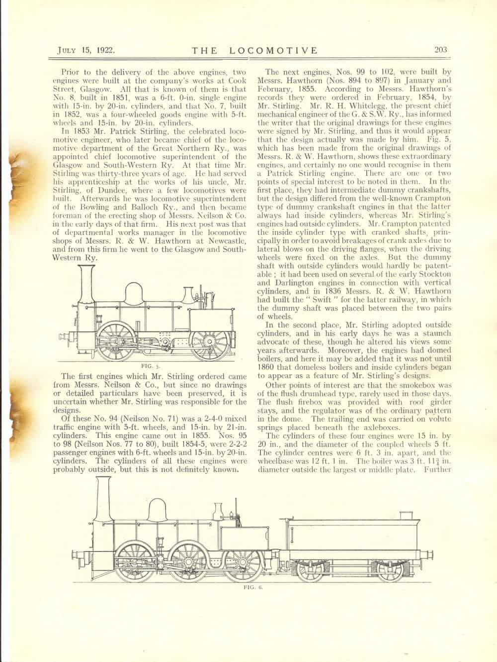
The next engines, Nos. 99 to 102, were built by Messrs. Hawthorn (Nos. 894
to 897) in January and February, 1855. According to Messrs. Hawthorn's records
they were ordered in February, 1854, by Stirling. R.H. Whitelegg, the present
chief mechanical engineer of the G. & S. W. Ry., has informed the writer
that the original drawings for these engines were signed by Mr. Stirling,
and thus it would appear that the design actually was made by him. Fig. 5,
which has been made from the original drawings of R. & W. Hawthorn, shows
these extraordinary engines, and certainly no one would recognise in them
a Patrick Stirling engine. There arc one or two points of special interest
to be noted in them. In the first place, they had intermediate dummy crankshafts,
but the design differed from the well-known Crampton type of dummy crankshaft
engines in that the latter always had inside cylinders, whereas Stirling's
engines had outside cylinders. Crampton patented the inside cylinder type
with cranked shafts, principally in order to avoid breakages of crank axles
due to lateral blows on the driving flanges, when the driving wheels were
fixed on the axles. But the dummy shaft with outside cylinders would hardly
be patent- able; it had been used on several of the early Stockton and Darlington
engines in connection with vertical cylinders, and in 1836 R. & W. Hawthorn
had built the Swift for the latter railway, in which the dummy shaft
was placed between the two pairs of wheels.
In the second place, Stirling adopted outside cylinders, and in his early
days he was a staunch advocate of these, though he altered his views some
years afterwards. Moreover, the engines had domed boilers, and here it may
be added that it was not until 1860 that domeless boilers and inside cylinders
began to appear as a feature of Stirling's designs. Other points of interest
are that the smokebox was of the flush drumhead type, rarely used in those
days. The flush firebox was provided with roof girder stays, and the regulator
was of the ordinary pattern in the dome. The trailing end was carried on
volute springs placed beneath the axleboxes.
The cylinders of these four engines were 15 in. by 20 in., and the diameter
of the coupled wheels 5 ft. The cylinder centres were 6 ft. 3 in. apart,
and the wheelbase was 12 ft. 1 in. The boiler was 3 ft. 11 ~ in. diameter
outside the largest or middle plate. Further particulars are not known. The
engines did not have a very long career, for after eleven years of ser- vice
Mr. P. Stirling replaced them by new goods engines in 1866.
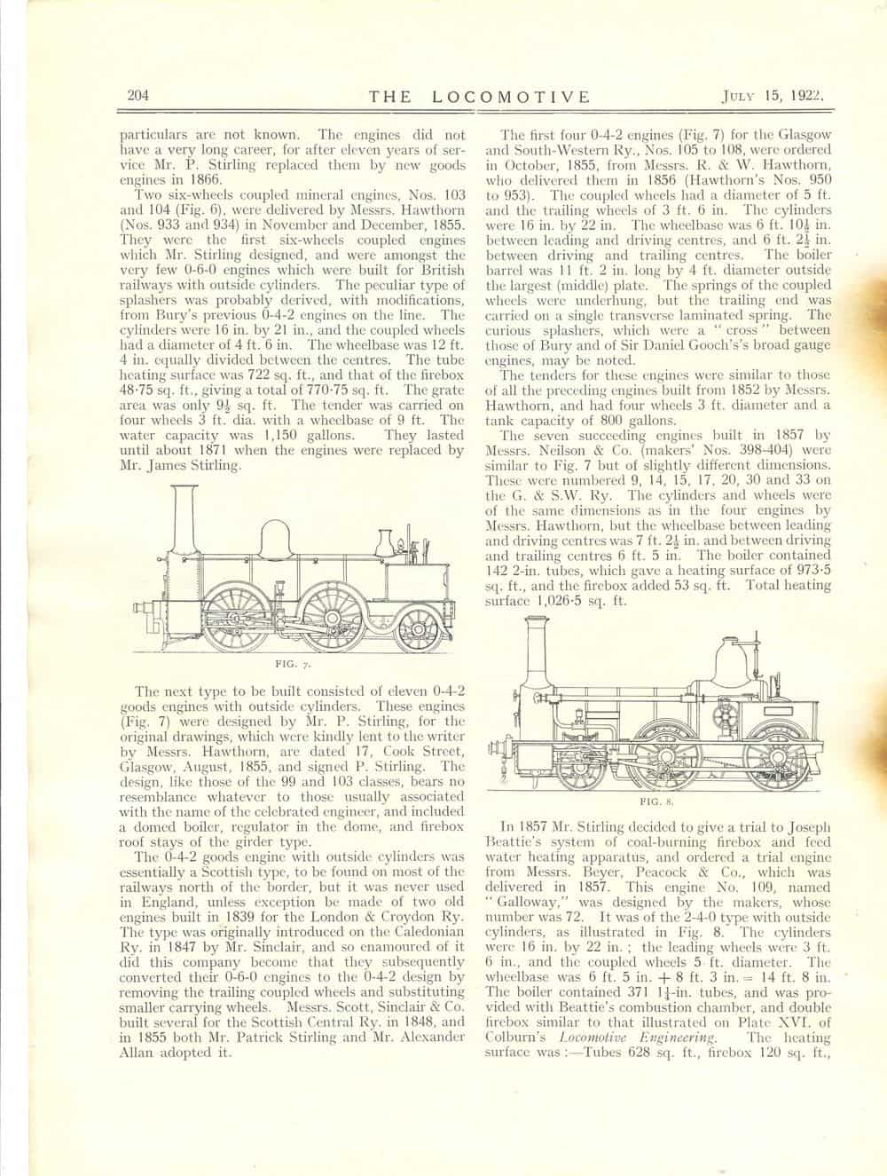
Two six-wheels coupled mineral engines, Nos. 103 and 104 (Fig. 6), were delivered
by Messrs. Hawthorn (Nos. 933 and 934) in November and December, 1855. They
were the first six-wheels coupled engines which Mr. Stirling designed, and
were amongst the very few 0-6-0 engines which were built for British railways
with outside cylinders. The peculiar type of splashers was probably derived,
with modifications, from Bury's previous 0-4-2 engines on the line. The cylinders
were 16 in. by 21 in., and the coupled wheels had a diameter of 4 ft. 6 in.
The wheelbase was 12 ft. 4 in. equally divided between the centres. The tube
heating surface was 722 sq. ft., and that of the firebox 48·75 sq. ft.,
giving a total of 770·75 sq. ft. The grate area was only 9! sq. ft.
The tender was carried on four wheels 3 ft. dia. with a wheelbase of 9 ft.
The water capacity was 1,150 gallons. They lasted until about 1871 when the
engines were replaced by Mr. James Stirling.
The next type to be built consisted of eleven 0-4-2 goods engines with outside
cylinders. These engines (Fig. 7) were designed by P. Stirling, for the original
drawings, which were kindly lent to the writer by Hawthorn, are dated 17,
Cook Street, Glasgow, August, 1855, and signed P. Stirling. The design, like
those of the 99 and 103 classes, bears no resemblance whatever to those usually
associated with the name of the celebrated engineer, and included a domed
boiler, regulator in the dome, and firebox roof stays of the girder type.
The 0-4-2 goods engine with outside cylinders was essentially a Scottish
type, to be found on most of the railways north of the border, but it was
never used in England, unless exception be made of two old engines built
in 1839 for the London & Croydon Ry. The type was originally introduced
on the Caledonian Ry. in 1847 by Mr. Sinclair, and so enamoured of it did
this company become that they subsequently converted their 0-6-0 engines
to the 0-4-2 design by removing the trailing coupled wheels and substituting
smaller carrying wheels. Scott, Sinclair & Co. built several for the
Scottish Central Ry. in 1848, and in 1855 both Patrick Stirling and Alexander
Allan adopted it.
The first four 0-4-2 engines (Fig. 7) for the Glasgow and South-Western Ry.,
Nos. 105 to 108, were ordered in October, 1855, from R. & W. Hawthorn,
who delivered them in 1856 (Hawthorn's WN 950 to 953). The coupled
wheels had a diameter of 5 ft. and the trailing wheels of 3 ft. 6 in. The
cylinders were 16 in. by 22 in. The wheelbase was 6 ft. lOt in. between leading
and driving centres, and 6 ft. 2! in. between driving and trailing centres.
The boiler barrel was 11 ft. 2 in. long by 4 ft. diameter outside the largest
(middle) plate. The springs of the coupled wheels were underhung, but the
trailing end was carried on a single transverse laminated spring. The curious
splashers, which were a "cross" between those of Bury and of Sir Daniel Gooch's
broad gauge engines, may be noted.
The tenders for these engines were similar to those of all the preceding
engines built from 1852 by Hawthorn, and had four wheels 3 ft. diameter and
a tank capacity of 800 gallons.
The seven succeeding engines built in 1857 by Neilson & Co. (WN 398-404)
were similar to Fig. 7 but of slightly different dimensions. These were numbered
9, 14, 15, 17, 20, 30 and 33 on the G. & S.W. Ry. The cylinders and wheels
were of the same dimensions as in the four engines by Hawthorn, but the wheelbase
between leading and driving centres was 7 ft. 2½ in. and between driving
and trailing centres 6 ft. 5 in. The boiler contained 142 2-in. tubes, which
gave a heating surface of 973·5 sq. ft., and the firebox added
53ft2. Total heating surface 1,026·5ft2.
FIG. 8. In 1857 Stirling decided to give a trial to Joseph Beattie's system
of coal-burning firebox and feed water heating apparatus, and ordered a trial
engine from Beyer, Peacock & Co., which was delivered in 1857. This engine
No. 109, named Galloway, was designed by the makers, whose WN
was 72. It was of the 2-4-0 type with outside cylinders, as illustrated in
Fig. 8. The cylinders were 16 in. by 22 in.; the leading wheels were 3 ft.
6 in., and the coupled wheels 5 ft. diameter. The wheelbase was 6 ft. 5 in.
+ 8 ft. 3 in. = 14 ft. 8 in. 4 The boiler contained 371 1¼in. tubes,
and was provided with Beattie's combustion chamber, and double firebox similar
to that illustrated on Plate XVI. of
Colburri's Locomotive
Engineering. The heating surface was :-tubes 628 ft2,
firebox 120 ft2, combustion chamber 662, toal 814
ft2. grate area 16.1 ft2. The six-wheel tender had
3ft 6in wheels. No. 109 ran until 1874.
|
|
T.H. Sanders. Laminated railway springs Section IV. Spring suspension.
Sub-section A. Locomotives and tenders. 205-7. 4 diagrams
Longitudinal equalizers. Beams were common in the USA and on Continental
Europe. Six wheel tenders were typically British. The rigid eight wheel tender
was used on the LYR. Bogie tenders were the norm in the USA and springs to
liit sideplay are described.
Great Central Ry. 207.
No. 1090, the three-cylinder Atlantic 4-4-2 was being converted to
two-cylinders. A new boiler with superheater and piston valves were also
being fitted. Intensifore lubricators were being fitted. Two of Robinson's
older 4-4-0s, Nos. 1031 and 1039, were being fittted with larger boilers
with superheaters and extended smokeboxes, new cylinders with piston valves,
ash ejectors and Wakefield lubricators.
Two Wrexham, Mold & Connahs Quay 0-6-2STs, Nos. 405B and 406B, had been
withdrawn
New South Wales Governments Rys. new cars for Sydney suburban passenger
traffic. 208-9. 2 illustrations
Steam hauled stock, but built to conform for simple conversion to
electric trailer cars. Had sliding doors and vestibule connections.
Recent standardization in China. 209-11.
Yeh Kung Cho, Chinese Cice Minister of Communications visited Europe
to appoint foreign advisors to assist in developing the country's railways.
Initial talks took place with the American, French and British ggovernments
and later Belgian and Japanese interests were involved, Standards for steel
bridges, freight cars, couplers and locomotive parts were agreed.
A.R. Bennett. The chronicles of Boulton's Siding. Chapter XVII. Broad
gauge (7 feet) locomotives. 211-13. illustration (diagram (side elevation)
In December 1872 bought four four 0-4-0 tank engines from the Holyhead
Breakwater. They had been built in 1852 by R.B. Longridge & Co.
of Bedlington and were well tanks named London, Holyhead, Cambria
and possibly Queen. These were converted into winding or stationary
engines. Prince Albert remained at Holyhead and hauled the Prince
Consort when en route to the Dublin Exhibition in 1853 and later performed
the same task for the Prince of Wales when he opened the Breakwater. In 1901
it was sold to W. Wild & Sons who withdrew it in 1913 when the railway
was converted to standard gauge, In 1853 E.B. Wilson & Co. built similar
locomotives for the Portland Breakwater
New oil tank wagons for India. 214-15. 4 illustrations
Great Indian Peninsular Railway: tank wagons, including bogie vehicles
built at the Mutanga shops
[Obituary]. 216. illustration (portrait)
John Charles Taite was born in London on 8 May 1852, was educated
at Crawford College. He served his time at the works of John Dewrance and
Co., afterwards going as an improver to Sharp, Stewart and Co., Atlas Works,
Manchester, and then to Nasmyth Wilson and Co., Patricroft. In 1875, in
partnership with T.W. Carlton, whose father was Manager
of the Locomotive Works of the Great Western Railway at Swindon, he established
the firm of Taite and Carlton. The firm was largely interested in the
introduction of pressed steel wagons and under-frames for British and Colonial
railways, and introduced the Holden liquid fuel burner, the invention of
James Holden, Locomotive Engineer of the Great Eastern Railway. This was
extensively used in the oil-producing countries, particularly South Russia,
Rumania, etc. Taite attended trials with this apparatus in the Mont Cenis
and other sections of the Italian State Railways, where difficulties owing
to asphyxiation of the engineers had occurred in the tunnels, and considerable
success resulted. This was, of course, prior to electrification. He was also
interested in the Worsdell two-cylinder compound engine which was still in
use on Argentine railways. Subsequently Taite became interested in pneumatic
tools and was Chairman of the Taite-Howard Pneumatic Tool Co., Ltd., until
it was taken over by an amalgamation of pneumatic tool companies. In this
connexion he read a Paper at the Glasgow Meeting of the Institution in 1901.
He was also Chairman of the Wycliffe Foundry Co., Ltd. which specialized
in the production of malleable castings. Died in London on 26 June
1922.
Engerth passenger engines. A.R. Bennett.
216. illustration
Being at Lille in July, 1910, I learnt that the Engerth locomotives
that for very many years had been largely engaged in the local traffic about
that important centre had recently been superseded by more powerful modern
tank engines and had been withdrawn from further service. Visiting Tourcoing
shortly afterwards I found several of these condemned Engerths in a siding
there awaiting convoy to Paris for breaking up purposes, and was able to
take the accompanying photograph. It will be noticed that the middle engine
is No. 2·415 which is illustrated in Fig. 12, page 106, of M. Jacquet's
article. The other two, 2·410 and 2·434, are mentioned on the previous
page. The foremost engine, 2·410, only the bunker of which shows in
the photograph, has side tanks like the one shown in M. Jacquet's Fig. 11.
On the track behind No. 2·415 can be seen, one of the new tank engines
by which the ancient stagers had been replaced. Remembering them; as I did,
for more than forty years, from the time when their entire boilers had been
sheathed in brass sheets, I was sorry to find them in such a forlorn situation.
They were to be scrapped, not for any working defects, but simply as too
light for the modern traffic. A few days later I was at St. Omer where I
found some half-dozen condemned tender engines similar to M. J acquet's Fig.
13, but all with the dome-of somewhat different shape- close up to the chimney.
They were apparently re-builds from Engerth passenger tanks and were also
awaiting transit to Paris. Unfortunately photographs in this case were
impracticable and it did not occur to me to note the numbers.
Correspondence. 216.
Locomotives of the Glasgow & South Western Ry.
J. H. Alexander.
Being an Ayrshire man, I am much interested in the articles by Mr.
Ahrons. About twenty-five years ago, there appeared
in the LOCOMOTIVE MAGAZINE, from my pen, * an account of the Duke of
Portland's old horse-driven tramway line (now part of the G. & S. W.
Ry.) running from Kilmarnock to the harbour at Troon. This article. was
illustrated from photos of the cast-metal plate rails and of some of the
bridges still standing, one being that at Drybridge station, which has the
date of 1811 cut out upon it, Before publishing that account I carried out,
at different times. some researches to try if I could find any real authentic
information about the loco. which was tried on the tramway at Kilmarnock
and said to have been the first locomotive in Scotland. I searched through
many old files of newspapers and journals from 1814 to 1822 in Glasgow,
Kilmarnock and Troon; I also interviewed the late Mr. James Stirling (once
loco. superintendent of the G. &S. W. Ry.), as well as a few old railway
men and drivers; I also wrote to Messrs. Robt. Stephenson & Co., Ltd.,
Darlington, who said" they had no records of these very early locos. made
by Geo. Stephenson." I heard a little from some and less from others but
my informants had only obtained their information 'from, hearsay, so the
results of my investigations were disappointing. However,.I happened to come
across some information, given in an old book by one who, unfortunately,
was not an engineer. I refer to a book, by a local Ayrslure artist, called
Hunter, entitled Reminiscences of an Artistic Life." Hunter says that
in 1816 (not 1817, as given by Mr. Ahrons), 'he was present at the trial
run at Gargieston, near Kilmarnock, on the Duke of Portland's tramway line,
of a locomotive; everything was satisfactory, but the weight of the engine
broke some of the cast-iron tram plates and it was removed; that a man called
Geordie Pettigrew was the driver of the first "steam horse" in Scotland and
was regarded as a hero by everybody in the district; and that the locomotive
was built by George Stephenson, and brought by his brother James from Newcastle
to Kilmarnock. Whether it came by road or was shipped to Troon he does not
say. Hunter speaks of the vertical cylinders, the coupling chain between
the axles, and gives the impression that the engine had six wheels, instead
of four, under the boiler. Were any six-wheel locomotives built by Stephenson
at that early period of his career?
Hunter, though not an engineer, was an eye witness and his work called for
more observation than usual on his part and this fitted him to relate his
impressions with truth, therefore, I consider that he may be regarded as
worthy of reliance. I have not been able to discover what was the final destiny
of this old locomotive called The Duke, whether she was sold to some
other company or later on was put to work on the G. & S. W. Ry. So far
as I know there are no records extant (except that given by Hunter) and there
is nothing, but hearsay to depend on. I may add that working drawings of
what this early locomotive of Stephenson was supposed to be like were made
from my notes and a silver model of the engine constructed in Troon. The
draughtsman made it a six-wheel locomotive (not four wheels) without flanges
and with chain coupling. Six steam supporting springs were put under the
boiler. The reversing was performed by loose eccentrics and the after plate
of the boiler, containing the firedoor, was arranged to draw out and this
appeared like a grocer's scoop, its function being to contain a short address.
The engine rested on tram plate rails modelled from one of old tramway rails.
The model, along with an address, was presented by the Corporation of Troon,
in 1914, to the present Duke of Portland, on the occasion of his silver
wedding.
Locos. of the G. & S.W. Ry.
Editor. 217.
With regard to the letter from C. Chambers, which appeared on page
184 of the June number, we should be glad if our correspondent would send
the particulars of the missing Glasgow and Ayr engines. to which he referred,
and add whether he can guarantee the information to be absolutely authentic.
The engines Nos. 7 and 8 were not rebuilt, but were broken up and replaced
by new engines.
Reviews. 217-18
The all electric age. A. Gowans Whyte, London: Constable & Co.,
Ltd.
>Written in a popular form this book should be welcomed by almost
every householder possessing an electric installation. The Birth of the
Electrical Industry is related in the first chapter followed in Chapter Il.
by How Electricity is Made- Electric Traction-Power Stations-Electric Lighting-
Heating and Cooking are dealt with separately and the labour- saving home
and its simple appliances affords an interesting chapter. Illustrations.
are frequent and very clearly produced throughout the book.
Model electric locomotives and railways. Henry Greenly, London Cassell
& Co., Ltd.
In this book of 306 pages the author has gathered a most varied and
interesting collection of photographs, diagrams, and working drawings, produced
with most admirable clearness, whilst the text is full of useful data and
informative details as to the practical construction of the model electric
loco- motive and its track. The opening chapter is a concise sum- mary of
the evolution of the full-size electric locomotive from the crude example
shown at the Berlin Exhibition of 1879, to the powerful machines built recently.
This introductory chapter is followed by others dealing with Notable Model
Electric Locomotives, How an Electric Motor Works, the Four-conductor System,
Electric Motors for Model Traction Purposes, Collecting Shoes, Overhead Bows
and Track Bonding, Signals, Power Supply, etc. The book is to be recommended
as a most useful manual to all who are interested in model engineering.
The lead storage battery. H.G. Brown, London: The Locomotive Publishing
Co., Ltd.
In designing this work on the Lead Storage Battery Brown has apparently
had in mind the state of mind of (1) the engineer who is perfectly familiar
with prime movers, and distribution schemes, but is not quite so sure of
his secondary cells; (2) the electrician with more or less indefinite, not
to say confused, ideas of the working of secondary cells, and (3) the intelligent
layman interested in country house lighting sets or in the electrical system
associated with a motor vehicle. But be he engineer, electrician or layman
he will find in the book, in plain and definite language and with clear
elucidation of principles, the why's and wherefore's of secondary cells and
the best-known methods of maintenance procedure. It is not desired to imply
in the foregoing statement that the work is of a ponderous type. On the contrary,
it is a short work of only 141 essential pages, and deals with the chemistry
of secondary cells (so far as it matters to the user); the elec- trical
characteristics as regards capacity, voltage, etc. ; the formation and structure
of plates; erection; use of boosters, regulators and auto cut-outs; treatment;
maintenance and repairs; testing; economics, etc., whilst the further treatment
of the chemistry of the cell is left to appendices, as is also the method
of carrying out simple analytical tests to determine the quality of water
and acid intended for secondary cell use. Chapter 1. is a short resume of
the chemistry of the lead plate secondary cell. The double sulphate theory
is given, (and wisely left at that), with the object of explaining the reason
for the changes in specific gravity and the voltage on charge and discharge.
In Chapter n. the electrical characteristics with regard to charge and discharge
voltages, and ampere-hour capacity, are treated in a very clear and concise
manner. Valuable and interesting charts are presented, namely:-- (1) Rate
of fall of open circuit voltage on a cell left idle for a number of hours
after being fully charged. (2) Ratio of specific gravity of electrolyte and
open circuit voltage. (3) Discharge voltages at different rates of discharge
currents. (4) Charge voltage at different rates of charge currents and (5)
Effective ampere-hour capacity at different discharge rates. (Two charts).
Of particular interest is the author's treatment of the formation and strncture
of plates in Chapter Ill. The reason for the different plate formations is
set out. The significance of the statements on pages 27 and 32 with regard
to the relation between ampere-hours capacity and thickness of plates,
expounding, as these statements do the compromise between thin plates and
frequent renewals or thick plates and longer service, will be apparent.
Chapter TX. deals with the design and arrangement of large secondary batteries.
Wood separators vprsus rod separators is touched upon on pages 37 and 38.
The proviso that a wood separator is an advantage" as long as it remains
intact" is, however, not a very convincing argument in favour of wood separators.
In commenting upon the working ·of batteries in parallel the author
reaches the crux of the whole difficulty attending this principle in his
concluding paragraphs, namely, the liability of disturbance of electrical
equilibrium in respect of resistance or physical condition of plates and
although separate voltmeters and ammeters are recommended whenever the
parallelling method is resorted to, the difficulties which may attend any
attempt to rectify the absence of balance might with advantage have been
made clearer.
Number 360 (15 August 1922)
Six-coupled tank locomotive, East Indian Railway. 219. illustration
Hunslet outside-cylinder 0-6-0T built to specification and inspection
of Rendel, Palmer & Tritton, consulting engineers. Cylinders: 18 x 24-in;
4-ft diameter wheels; total heating surface 1001
ft2, grate area
19.7ft2; boiler pressure 160 psi.
[Lynton and Barnstaple Ry.]. 219
Absorption by the London & South Western Railway (was outside
grouping Act of 1921)
[Pullman train for Clacton on Sundays]. 219
From 30 July
Superheater 4-4-0 express locomotive, L. &
S.W.R. 220-1. illustration, 2 diagrams (side elevations)
Fitted with new larger (icreased from 18½ to 19 inches diameter
cylinders, but retaing slide valves. New total evaporative surface
1063ft2 plus 195ft2
superheat
Narrow-gauge locomotives Larkhana Jacobabad Ry. of India. 221-2. illustration
Australian 3ft 6in gauge locomotives. 222-5. 5 illustrations
4-6-0 for Queensland Government Railways
Caledonian Ry. 226
Twenty new engines had been ordered from the North British Locomotive
Co., and 500 mineral wagons from Hurst, Nelson & Co., Ltd.
North British Ry. 226
Ten 0-6-2T engines had been ordered from Robert Stephenson & Co.,
Ltd., of Darlington, and several new engines are to be built at Cowlairs
shops.
London & North Western Ry. 226
The two latest Horwich-built four-cylinder 4-6-0 passenger engines,
Nos. 1657 and 1658, were stationed at Crewe, together with one of the rebuilt
engines. No. 1511. They were all fitted with eight-wheeled tenders.
Saddle tank locomotive for the Wolverton & Stony Stratford Tramway,
L.& N.W, Ry. 226. 2 illustrations
0-4-0ST built by W.G. Bagnall, Ltd., of Stafford. This Tramway, which
was opened in 1891, and built on the 3-ft. 6-in. gauge, was used principally
for conveying employees of the carriage works, between Wolverton and Stony
Stratford, where they resided, a distance of two miles. It was taken over
by the L. & N. W. Ry. in 1921. Major dimensions given.
E.A. Forward. Some forgotten Crampton locomotives.
226-7. 2 diagrams (including side elevation)
Built by Kitson & Co. of Leeds for the Midland Railway and fitted
with Dodds valve gear. Had massive frames
The "Mackelson" automatic coupler. 227-8. diagram
Great Western Railway. 228
The following appointments had been made: W.A. Stanier, formerly Works
Manager, to be Assistant to C.B. Collett; R.A.G. Hannington, formerly Manager
Car and Wagon Department, to be Manager Locomotive Department; E.T.J. Evans,
formerly Assistant Manager Car and Wagon Department, to be Manager Car and
Wagon Departmen; J. Auld, to be Docks Assistant to C.M.E. ; C.J. Riches to
be Divisional Locomotive Superintendent, Cardiff Valleys Division
A.R. Bennett. The chronicles of Boulton's Siding. Chapter XVII. Broad
gauge (7 feet) locomotives. 229-31. diagram
Continued from page 213.
The Paris-Orleans Ry. 231
Order for eighty electric locomotives with the Societe Oerlikon and
the Societe de Construction des Batignolles, both of Paris ; these locomotives
are each for a one hour rating of 1720 H.P. The Societe Oerlikon is to supply
and erect the electrical equipment, while the Societe de Construction des
Batignolles deals with the mechanical part. Except in the case of the five
first locomotives, which will be completed at the Swiss works of the Ateliers
de Construction Oerlikon, and will serve as models, the whole electrical
equipment will be built in France, to the Oerlikon design, at the works of
the Societe Oerlikon. The locomotives are specially intended for goods trains
and are to be capable of hauling a load up to 1200 tons ; they are, also
to be suitable for passenger service, in which case a speed of about 68 miles
per hour must be attainable.
Continental sleeping cars. 232
“We understand” that the contract for forty all-steel railway
coaches for Trans-European passenger services, being executed by The Leeds
Forge Co., Ltd., amounts to approximately £500,000, and is the biggest
contract of its kind that has ever been placed in Leeds. The first completed
coach has recently been despatched to France, via Immingham and the train
ferry.The order was received from the International Sleeping Car Company,
in October, 1920, and the Leeds company secured the contract in face of British,
Belgian and German competition. They were beaten on price by Germany, but
the deciding factor in sending the order to Leeds was the preference for
the Forge Company's design. The International Sleeping Car Company's express
services are: Paris Bucharest; Paris Prague Warsaw; Ostend Berlin Riga ;
Ostend Vienna ; Ostend Bucharest, etc. It is for such long-distance work
that the cars being built at the Newlay works of the Leeds Forge Company
are intended. These would be the first all-steel carriages to operate on
the continent, though similar ones run in the United States. The first six
are to work on the P. and O. service between Calais and Marseilles. At present
twenty cars are in course of construction. It is hoped to deliver a coach
each fortnight, so that the contract should be finished by the end of 1922.
Each car provided accommodation for sixteen passengers. There were four
single-berthed compartments and six with double berths, with hot and cold
water laid on to each compartment. In addition to the ordinary electric lighting,
reading lamps were fixed in the walls above the pillows. The seats were
reversible and could be changed into beds at will.
The Newlay works of the Leeds Forge Co., Ltd., were converted from a shell
factory to cope with the present work, which is quite a new industry to the
district. Some 450 men are employed there, but many of the key men have had
to be imported from other districts, and they have suffered the disadvantages
of the housing shortage. Unless remedied, this may have a detrimental effect
on future contracts. The present contract had brought work not only to Newlay,
but to the Armley works of the company as well as those of the subsidiary
company at Bristol, and evidence that these cars are an international product
was furnished by the fact that Scotland, Wales, France, Italy and Belgium
contributed parts. This firm had secured from the Crown Agents for the Colonies,
the contract to build thirty 20-ton all-steel bogie covered wagons for the
Gold Coast Railway
T.H. Sanders, Laminated railway springs. Section IV. Spring suspension.
Sub-section A. Locomotives and tenders. 232-4. 4 diagrams
Laminated springs for bogies (more common on the Continent than in
UK). Similar small laminated springs are sometimes applied, chiefly in the
U.S.A., to counterbalance the valve motion reversing shaft, in place of the
more usual weight. Fig. 162 illustrates numerous examples of overhung engine
and tender springs, as follows : All these springs are drawn straight, and
most of them are suitable for so working, and even with reverse
cambers.
P.C. D[ickinson]. The Midland and Great Northern Joint
Railway and its locomotives. 234-5, 2 illustrations
Continued from page 178. Modifications to the standard four coupled
bogie express engines of the Joint Line. In 1906 engine No. 55 was worked
experimentally with cylinders lined up to 17 in. diameter. In the same year
No. 79 was fitted with a deflector or Capuchon on the chimney top, this being
applied to an ordinary Johnson pattern of chimney, but after a time it was
removed. Following a few months after this extended smokeboxes began to be
fitted, among the earliest being Nos. 14, 17 and 46 ; they were all of the
flush circular extension type as shown in Fig. 23 (page
49). In 1908 the large-boiler rebuilds of these engines began, Nos. 39
and 55 being turned out from Melton Constable works in that year; they were
both fitted with standard Midland H class boilers, with round-topped fireboxes,
having boiler mountings and cabs of the period (1907 pattern), but the smokeboxes
were not the Derby style, being of the flush circular extension type.
The boilers of these engines, however, although externally similar, differed
in respect of tubes and heating surface. No. 39 (shown in Fig. 28) total
heating surface 1,428 ft2; 21,1
ft2 grate areas and operated at 175 psi. This boiler
was applied to goods engines as well as earlier passenger rebuilds on the
Midland, 21,1 ft2 The boiler fitted to No. 55 was of the later class as used
by . Deeley in the 2000 class and in the later passenger rebuilds until
superseded by the Belpaire: total heating surface
1,347ft2 and different tube
dimensions. The numbers were separate solid brass figures as before,
but of considerably larger size. It should be noted that No. 55 when first
put into service was fitted with a Midland taper chimney of the Deeley (1904)
pattern, but No. 39 and all others subsequently rebuilt were provided with
the 1907 Midland parallel pattern with deflector lip. No. 55 and goods engines
Nos. 62 and 69 when rebuilt were, we believe, the only instances of the Midland
1904 taper chimney being used on the Joint locomotive Two further large-boiler
rebuilds were completed in 1909-10, Nos. 45 and 53; these were supplied with
Midland non-superheater Belpaire type boilers similar to those fitted to
the Midland 6-ft. 6-in. class of 4-4-0 (Nos. 386, etc.), from 1909 onwards,
but the smokeboxes were of the Melton Constable pattern and the engines also
differed from the Midland rebuilds in that the original plain pattern of
coupling rods are retained. Fig. 29 illustrates No. 45. These were followed
by 56 and 57 in 1912 ; 52 in 1913,54 in 1914 and 46 and 51 in 1915. The
dimensions of the Belpaire boilers of the later rebuilds were total.heating
surface 1,410ft2 . Grate area
21.1ft2 . Working pressure 175 psi.
Many of the same class have been rebuilt with boilers similar to their original
boilers and extended smokeboxes. From 1908 when the first of the large boiler
rebuilds was put in service the enlarged class were always used on the through
Leicester trains, two being stationed at Norwich for the purpose. (To be
concluded.}
New Baltic type locomotive engine, Glasgow & South Western Railway.
236-7. 2 diagrams
Further detailed working drawings (cross sections)
G. Willans. Locomotive feed water heating and boiler feeding. Section
2 boiler feeding. 237-8. 2 diagrams
All the apparatus hitherto described constitute what has now become
known as top-feed, and the Churchward arrangement introduced on the Great
Western Railway about 1912 is shown in Fig. 40. This is now the standard
method of boiler feeding on that railway, since which time many other railways
have followed this practice, differences in design being introduced, but
the top-feed principle being to all intents identical with the Great Western
Railway practice. The following examples are mentioned to illustrate the
various applications of the top-feed on different British Railways. In the
Weir apparatus already described, using the special spraying valve previously
shown, this device consists of a spring loaded valve which, when the feedpump
is operating, serves to break up the feed-water into a spray or film of water,
which is, therefore, more readily heated by its contact with the boiler steam,
to be a form of the Chapsal arrangement, had been fitted to several Great
Northern Railway engines by Gresley. The feed enters the top of a special
dome, thence on to an arrangement of trays, finally overflowing past the
"weirs" into the boiler. This arrangement has the advantage of acting as
a small live steam heater and also as a sediment drum, whereby a considerable
amount of sediment may be collected that would otherwise pass into the boiler.
A somewhat similar arrangement making use of a special dome for the purpose
of the feed-supply was shown on page 242 of Vol. xxii. and which has been
adopted by Maunsell on several engines on the South Eastern and Chatham Railway.
Here there is no special arrangement to obtain the fullest possible contact
of the feed-water with the boiler steam, as in the Chapsal arrangement, though
a certain result of this nature should follow from the passage of the feed
down what may be described as "the helter skelter" and on to the saddle plates.
Whether when the engine is in service, the feed-water does actually allow
itself to be constrained by the helix, or overflows in the line of least
resistance, is questionable there is also no attempt made to use the feed-dome
as a collecting medium for the deposit, which passes into the boiler in the
same way as the other less elaborate methods.
Top feed arrangements are also used on the Great Central, Midland, Great
Eastern and Rhymney Railways, and have been tried on certain engines in India,
and the States, but the foregoing cover the field of recent applications
of this method of boiler feeding, which can be confidently stated to have
"come to stay." Although the Great Western Railway is at present alone in
its universal adoption, it seems certain that in the course of time the top
feed will come to be considered as the modern equivalent of " the old-fashioned
place" mentioned by Mr. Stirling at the commencement of this section of the
subject. To be continued.
Ljungstrom steam turbine locomotive. 238
We understand that the experimental results that the experimental
results achieved by the Ljungstrom turbine driven locomotive, now working
upon the Swedish State Railways, have proved very satisfactory. It is said
that a fuel economy of 52 per cent, over the consumption of ordinary
reciprocating engines has been attained, and that the machine works with
great mechanical efficiency.
Saloon for H.E. the Governor of Bombay. 242. 2 illustrations
Recent examples of British-built rolling stock. 243-6. 6 illustrations,
2 diagrams
Cammell, Laird & Co., Ltd., had built vehicles at their new works
in Nottingham to the designs of the London Electric Railways including. trailer
control cars for the Piccadilly Line. Cammell, Laird had also supplied high
capacity bogie freight vehicles, for carrying iron ore on the Bengal-Nagpur
Ry., 5-ft. 6-in. gauge lines; a diagram shows the diischarge nechanism; Clayton
Wagons, Ltd., supplied end and side tipping wagons to the Bombay Improvement
Trust: 4ft 8½-in gauge lines ordinary freight stock has to stand rough
usage, but the worst treatment it receives is mild compared with that which
is the share of contractor's stock on new works, Hurst, Nelson & Co.,
Ltd., supplied the Sudan Government Railways, 3-ft. 6-in. gauge both four-wheel
tank wagons with a carrying capacity of 12 tons, with a tare of 9-6 tons,
and bogie tank wagons with a carrying capacity of 26.5 tons, with a tare
weight of 19.2 tons.
Steel carriage stock for the Tientsin-Pukow Rly., China. 246-7. illustration
F.W. Brewer. Some notes on the efficiency of locomotive engines in relation to power and speed. 247-9.
Renouf's patent buffer shoe. 249-50
No. 361 (15 September 1922)
Three-cylinder express locomotive, Danish State Rys., 251-3. illustration,
5 diagrams
Three independent sets of Walschaerts valve gear, built by Borsig
to specication of A. Floor, chief mecanical engineer
Ten-coupled tank locomotive Bombay Port Trust Railway. 255.
illustration
2-10-2T supplied by Nasmyth, Wilson & Co
Rail motor car, Weston Clevedon and Portishead Light Ry. 255-6. illustration
Electric passenger locomotive, North Eastern Railway. 256; 257. illustration, diagram (side & front elevations & plan)
British and American locomotives. 258-9
Abstract of Dewrance IMechE
paper
"Clacton-Pullman" express. 260. illustration
A.R. Bennett. The chronicles of Boulton's Siding. 260-2.
A special vehicle for testing bridges. 263
Swiss Federal Railways
Number 362 (14 October 1922)
Rebuilt express locomotive, London Brighton & South
Coast Railway. 287-8. illustration, diagram (side elevation)
L.B. Billinton rebuild with Belpaire boiler of earlier 4-4-0 No.
55
[Bowman Malcolrn retirement]. 288
On the 30 October 1922 Bowman Malcolrn, M.LC.E., M.LM.E., retired
from the position of engineer and locomotive superintendent of the northern
counties section of the Midland Railway. Malcolm was the oldest locomotive
superintendent in the British Isles, and at the time of his appointment,
in 1876, as locomotive engineer of the Belfast and N. C. Ry. was the youngest,
being only twenty-two years of age. He started with the B. & . C. Ry.
in 1870. In 1906 when Berkeley D. Wise retired from the position of chief
engineer, the duties were transferred to Malcolm. Malcolm was one of the
first engineers to introduce high capacity rolling stock, putting into service
a number of 30-ton bogie wagons in 1892. He also used the Worsdell two-cylinder
compound system for a number of his express passenger engines, in conjunction
with the Walschaert valve gear, and obtained very satisfactory results in
practice. William Kelly Wallace has been appointed to succeed Malcolm, with
F.W. Crofts as engineering assistant, and H.B. [sic should be "P"] Stewart
as mechanical assistant.
Obituary. 288
E. A. Watson, general manager and engineer-in-chief of Beyer, Peacock
& Co., Ltd., died on 25 August 1922, after a long illness. Watson was
formerly chief mechanical engineer of the Great Southern and Western Railway
of Ireland, and before going to Inchicore was assistant works manager of
the Carriage and Wagon Works at Swindon.
North Eastern Ry. 288
Darlington works had been busy on a series of twenty-five six-coupled
superheater coal engines of Class P3, No. 2344 up, and had taken delivery
of the 0-6-0 side tanks, Class E1, built by Armstrong, Whitworth & Co.,
Ltd., No. 2313 up. Most of these were working in the Newcastle area. Hull
& Barnsley Ry. locos. have now been taken into the N.E. stock, with the
addition of 3000 to the old numbers.
The railways of Tasmania. 288-91. 2 illustrations, map
Old shops engine at Norwich, G.E.Ry. 307-8
P.C.D. The Midland and Great Northern Joint Railway and its locomotives. 310
Bombay Baroda and Central India Ry main line composite carriages. 315
Number 363 (15 November 1922)
Past and present locomotives — Great Northern Railway. 319.
illustration
Gresley Pacific No. 1471 and Stirling 8ft single No. 1
Clogher Valley Ry. 319
D.N. McClure appointed locomotive, carriage & wagon superintendent
in sucession to G.H. Akerlind. Was formerly with Rio Tinto Co. at Huelva
in Spain.
George Terrell. 319
Managing director Tyer & Co. MP. Elected President National Union
of Manufacturers.
Great India Peninsula Railway. 319.
Automatic train control to be installed on Jubbulpore to Itarsi
section.
An American freight locomotive of high efficiency.
320-2. diagram (side, front and cross section elevations)
2-8-2 built by Lima Locomotive Works for Michigan Central Railroad
No. 8000 to design of A.H. Smith, President of the New York Central Lines.
See also letter in Volume 29 page 156 from Wilkliam
Hoecker
The railways of Tasmania. 323-6. 8 illustrations,
table
Continued from page 290. Headquarters of Tasmanian Government Railways
in Launceston. Almost all locomotives had been suppplied by Beyer Peacock
& Co. Locomotives described and illustrated included No. A4 (a class
A 4-4-0 reboilered with a larger locally and fitted with a Pyle National
turbo-generator and headlight; No. C8, a 2-6-0; No. D1, a 2-4-2T; and No.
E1, a 4-8-0. Two railmotors (steam railcars?) were in operation in the west
on the Staverton line and on the Zeehan to Regatta line. There were 175 passenger
vehicles and about 1600 freight vehicles. The British Standard screw coupling
was used on the 3ft 6in gauge and the semji-automatic centre coupler on the
2ft gauge.The Chief Mechanical Engineer of the Tasmanian Government Rys.
was W.R. Deeble, whose offices were at Launceston. The Emu Bay Railway ran
from Burnie on the north coast 88 miles southwards to Zeehan, Its chief
mechanical engineer was A. Richardson with headquarters at Burnie. It used
a railmotor on the Waratah branch. No. 11, a 4-8-0 supplied by Dubs
& Co. is illustrated; later locomotives of this type had been supplied
by the North British Locomotive Co. David Jones was conulting engineer.
The Mount Lyell Ry. connected Strahan wwith Queenstown and had 123 miles
of route, of which 20 were 2ft gauge. Included 4½ miles of Abt rack
system where the line rose 850 feet. A Baldwin 0-6-0T with outside cylinders
is illustrated. The locomotive superintendent of the was R.C. Eyre, at
Queenstown.
Great Western Ry. 326
The following appointments have been made in the Locomotive, Carriage
and Wagon Department; C. Crump, London Divisional Superintendent, to be
Locomotive Running Superintendent and Outdoor Assistant to the Chief Mechanical
Engineer, Swindon. Mr. J. W. A. Kislingbury, Divisional Superintendent, Neatb,
to be Divisional Superintendent, London. Mr. F.C. Hall, Assistant Divisional
Superintendent, London, to be Divisional Superintendent, Neath. Mr. H. ].
Roberts, Mechanical Engineer, Port Talbot, to be Mechanical Engineer, Barry
Docks .. Mr. T. R. Herbert to be Mechanical Engineer, Port Talbot Docks,
and Mr. E. W. Green to be Mechanical Engineer, Newport Docks.
London, Brighton & South Coast Ry. 326
Another of the 4-4-0 express engines had been rebuilt at Brighton
similar to No. 55, illustrated in last issue. This is
No. 60. Ten of these engines were to be reconstructed.
Obituary. 326
Death of Prof. E. E. Foxwell, at St. John's College, Cambridge, on
the 18 October 1922, after a very brief attack of bronchitis. He was aged
seventy-one. Prof. Foxwell will be remembered as author of English Express
Trains, published in 1884, probably the first work published on the timing
of trains; and also joint author of Express Trains, English and Foreign
(1889.)
Four-coupled superheater express engine, with top feed water
heater. Great Eastern Ry. 327. illustration
D 56 class 4-4-0 No. 1794 fitted.
Great Central Ry. 327
Announced that new Director class to receive numbers 501-5 annd 511.
No. 501 named Mons and 502 Zeebrugge. Nos. 473 and 474 were
the last two of a series of express freight locomotives: Nos. 31-5 were new
series of 4 -6-0 freight locomotives being supplied by Beyer Peacock. 2-4-2T
No. 586 had been equipped for motor train (push & pull) working
The Glyn Valley Tramway. 328-9. 2 illustrations.
Tabulates locomotive stock.
W.B. Paley. Centenary of the Hetton Railway. 329-32.
3 illustrations, 2 diagrams
One illustration is taken from William Strickland's Reports on canals,
railways roads and other subjects, architectv and engineer for the Pennsylvania
Society for the Promotion of Internal Improvement, 1826. The two others show
the left and right hand sides of one of these running in the twentieth century.
Diagrams show the arrangement of the valve gear..
[William Burchell Paley]. 332
We are very sorry to have to record the sudden death of William Burchell
Paley, the well-known writer on locomotive history, which took place on the
22 October, at Bramerton Street, Chelsea. Mr. Paley was in his 68th year.
He was the eldest son of Professor F. A. Paley, LL.D., and grandson of Archdeacon
Paley, of Carlisle, who wrote the well-known Evidences of Christianity and
other works. He was educated at the Oratory School, Edgbaston, Birmingham,
under the late Cardinal Newman. After he left school he took up brewing and
was for some eight or ten years with a firm at Sheffield. Then he obtained
a post as clerk to the Lord Great Chamberlain and this he held for some
twenty-five years or more,, until he retired on pension two years ago. Mr.
Paley was a most industrious contributor of articles on early locomotives
and railways to the engineering papers. Apart from their literary merit these
have considerable value, owing to the accuracy with which he gathered his
facts, which were taken not so much from books as from personal investigation.
The article we print above was completed only a few days before his death.
Accidents at Cheadle Hulme and Furness Vale, L. & N.W.
Ry. broken connecting rods. 332-5
Both of the accidents involved locomotives fitted with Joy's valve
gear. On 28 April 1922, the left-hand connecting rod of Prince of Wales 4-6-0
No. 877 broke near Cheadle Hulme when running at about 60 mile/h, and pierced
the firebox: the fireman fell from the engine and was killed. The other involved
a 4-6-2T No. 1710 when working the 17.40 Manchester to Buxton commuter train
when fracture of the connecting rod led to the boiler being pierced and the
driver being scalded. The reports by the Ministry of Transport found that
the design of the valve gear was faulty andthat annealing of the connecting
rods was essential.
E. Lassueur. Recent locomotives for the Dutch Indies
Railways. 335-8. 4 illustrations, 2 diagrams
Includes the Javanic 2-12-2T developed from the 2-12-0T developed
by the Hanover Locomotive Co. 2-8-2T also described.
28-inch rolling mill. Messrs. Hadfield's, Ltd., Sheffield. 338-41. 2 illustrations
A.R. Bennett. The chronicles of Boulton's Siding. Chapter XVIII. Miscellaneous locomotives. 341-4. 4 diagrams
T.H. Sanders. Laminated railway springs. Section VI. Spring suspension. Sub-section A. Locomotives and tenders. 344-7. 3 diagrams
Questions and answers. 347-8.
No. 28 What is the correct formula for obtaining the tractive force of two,
three and four-cylinder compound locomotives?
An interesting War relic. 348. illustration
On 31 January 1916 there was a zeppelin raid on a large Midlands railway
wheel and axle works: photograph shows shrapnel damage to axles.
New steel carriages for suburban service, Great Indian Peninsula Ry.
349-50. 2 illustrations
Constructed at the Cammell, Laird & Co. works in Nottingham with
manual sliding doors, to be operated by compressed air once system electrified
and vestibuled throughout
Correspondence. 350
The Chronicles of Boulton's Siding. F.W. Brewer
Mr. Bennett's references to the experiments which were made with fireless
locomotives with a view to using such engines on the Metropolitan Railway
when the line was first opened in 1863, are very interesting. It is worth
while recording that although Sir John Fowler himself was responsible for
the "hot-water" engine, both he and Brunel maintained that the line could
be worked with ordinary locomotives. Having regard, therefore, to the immediate
success of the 4-4-0 condensing tank engines jointly designed by Sir John
Fowler and Beyer, Peacock & Co., in 1864, the previous attempts to produce
a satisfactory locomotive are not a little remarkable. At one stroke, as
it were, a type of engine was evolved that, with but few and comparatively
nnimportant modifications, continued in use for underground working for over
forty years; until the Metropolitan (and with it the Metropolitan District)
changed to electrical operation in 1905. Some thirteen of these Fowler engines
are still at work-on the Aylesbury line of the Metropolitan. The District
Railway had similar engines, and the L. 8: N.W.Ry., Midland Ry. and L. &
S.W.Ry., possessed a number of the type, as readers know.
Apart from the absence of smoke, the only justification for the fireless
locomotive notion was the belief that trains consisting of three carriages
and weighing 20 tons in all, exclusive of the engine, would suffice for the
prospective traffic, if run at intervals of five or ten minutes. In this
and other respects, the experts were at fault, for in the first year's working
of the Metropolitan Railway no less than 9,455,175 passengers were carried,
necessi tatin g trains of 1 20 tons in weight, instead of 20 tons only. In
1884, after the completion of the" circle," the passengers numbered 114,500,000,
and the receipts (which, for 1863, were £101,707) amounted to
£1,012,000. The" Underground" was consequently popular from its very
beginning. Owing, however, to the initially mistaken idea that ordinary
coal-burning engines could not be successfully employed, or, at any rate,
would not be necessary from the standpoint of power, the provision made for
ventilation was never as good as it would have been if the line had originally
been planned to be worked by such engines.
British and American locomotives: P.C. Dewrance. Edward
M. Gass. 350
Noted that latter writer was making reference to ten-coupled rather
than eight-coupled locomotives in relation to bridge stresses.
Review. 350.
Great Western Railway engines, 1922. A. J. L.
W. London: The Great Western Railway Magazine.
The publication of yet another edition of this work is unfailing testimony
to the popularity which it has achieved. This time the letterpress has been
entirely reset and the article on the Standardization of Locomotives enlarged
and brought up to date [KPJ italics]. Several new illustrations are
given, in some cases supplanting those of older types now obsolete, whilst
a half-tone block of the new Mixed Traffic Consolidation, No. 4705, appears
for the first time. When reviewing a previous edition we suggested it would
add to its interest if the dates and original numbers of the engines were
given, and we observe that in this issue the latter have been indicated in
the case... [damaged page]
Locomotives for gas works. Messrs. Andrew Barclay,
Sons & Co., Ltd., Caledonia Works, Kilmarnock, Scotland.
The subjects of this excellently produced pamphlet of sIxteen pages
are examples of locomotives that have been supplied by Andrew Barclay, Sons
& Co., Ltd., to various municipal and private gas companies, some of
them the largest and most important undertakings of the kind in Great Britain.
The types shown, though all of the 0-4-0 outside-cylinder construction, cover
a wide range of capacity and size, from 24 in. to standard gauge, and with
cylinders from 4 in. by 8 in. to 15 in. to 22 in. In accordance with the
requirements usual in this service, much ingenuity of design is displayed
in combining power wIth compact and simple construction. Two of the engines
shown, one of the 24-in. gauge for the Gas Light and Coke Company, and the
other having 4 in. by 8 in. cylinders for the Manchester Corporation Gas
Department, could hardly be surpassed for simplicity, every working part
and detail, even to the throttle valve, being fully accessible.
Types of fireless locomotives are also shown, one of which, designed to work
under retorts, has a vertical enclosed engine and gear drive, the whole of
the working parts being absolutely protected from dust, etc.
Number 364 (15 December 1922)
Ernest Lucy. Recent and future locomotive design in
New South Wales. 351-7. 3 illustration, diagram (side elevation)
S type 4-6-4T for working steeply graded Sydney suburban routes, NN
type 4-6-0 for main line passenger traffic and K class 2-8-0.
Pacific type express locomotive. North-Eastern Railway. 357-8.
illustration
Raven design
E. Lassueur. Recent locomotives for the Dutch Indies Railways. 360-4.
5 illustrations
Rack and adhesion locomotives to work from Padang to Panjang and Fort
de Kock to convey coal from the Ombilien mines on Sumatra. Locomotives built
at Esslingen and at Winterthur. Also illustraates and describes 2-6-2T for
working the Deli Railway from Medan to the Pangkalan-Brandan oil field.
The Wilson Welder and Metals Company's system of electric welding in repair
work. 364-6. 3 illustrations
Use for welding fireboxes in America
E.L. Ahrons. The locomotives of the Glasgow and South Western Railway. 366-70. 5 illustrations, 1 diagram (side elevation).
T.H. Sanders. Laminated railway springs Section IV. Spring suspension. Sub-section A. Locomotives and tenders. 370-3. 3 diagrams, table.
Correspondence. 372
Old shops engine Norwich. C.S. Allison.
Re an old twin-stationary engine recently withdrawn from service at
the G.E.R. shops at Norwich. It is there stated that the makers and exact
date of manufacture are unknown. The date of installation mentioned (" early
forties [1840s]) is doubtless correct.
As to the builders, I think there cannot be the least doubt but that it was
turned out by W. Fairbairn & Sons, of Manchester. It is what that eminent
engineer, Sir W. Fairbairn, called a "columnar engine and appears to have
been the standard type of that firm for high-pressure (non-condensing) engines.
If you will refer to Fairbairn's Mills and Millwork (first issue about
the end of the ffties and last edition, I believe, 1878, Longmans), you will
find the engine illustrated as in your block (only a single, not a twin),
Further, the Norwich engine had a geared connection to the shafting, and
this was Fairbairn's invariable practice (he did not believe in belt drives
from prime movers and says so in his book), What is more, he had a standard
type of built-up rim geared flywheel, which you will find fully illustrated
in the several fine mill engines (including the Saltaire engines) of which
he gives examples in his book. The Norwich flywheel is an exact Fairbairn
wheel of this type.
However, I can hardly accept the statement that the working pressure was
"originally" 80 Ib. per sq, in. Of course, this was a loco. shop and they
may have used a loco. type boiler (as Nasmyth did for his steam pile driver),
but if they relied on a Cornish, or more usually, an externally fired plain
cylindrical one, 80 lb would have been a fairly perilous working pressure,
knowing the very crude and haphazard methods of boiler-smiths in the "forties".
On this point again Fairburn gives tables compiled by Mr. Harman, chief inspector
of the Association forv the Prevention of Boiler Explosions, from the
returns for the years 1858-1860. As late as this he shows there were twenty
engines working above 60 lb, except a few "compounds".
Our Supplement: Baltic type tank locomotives, Glasgow & South Western Ry. 374 + plate
Mechanical couplers on the Indian broad-gauge railways. 374-6. 4 illustrations
Railways in industrial plants. 377-9. 2 illustrations, 3 diagrams
Switches and crossings and tuntables in cast iron or steel manufactured
by Robert Hudson & Co. of Gildersome.