Journal Institution of Locomotive Engineers
Volume 25 (1935)
| Steamindex home page Updated 2017-12-03 | Key file | The IMechE virtual library is accessible (full papers, all diagrams, photographs, extensive tables, etc).available via SAGE |
Journal No. 123
Sedgfield, J.R. (Paper 333).
Machine tooling methods and machine shop re-organisation. 1-84. Disc. 84-110.
[Part 2] 112-60. Disc.: 160-72.
Presented at the Perez workshops Central Argentine Railway on Friday
23 March 1934 chaired by J.G. Mayne.The Paper was built round the work of
these shops and this includes the illustrations and a folding plan of the
layout of the Works.
There were seven specialised locomotive machine shop sections where the machines
were grouped together to perform certain ranges of work:
Wheel Section.
Axlebox Section
Crosshead Section
Rod Section
Motion Work Section
Brake Gear Section
Boiler Stay Production Section.
As most of the more interesting and important locomotive machining operations
were performed in these sections, they were dealt with in some detail, section
by section. The remainder of the machine shop can also be divided up conveniently
into four separate sections:
Fabrication Section.
Brass Shop.
Tool Room.
General Section.
The specialised brake gear section and the general section do not offer any
points of particular interest, and they will therefore be dealt with last
of all and in as abbreviated a manner as possible.
Presentation of thr Alfred Roslin Bennett Award to C.A.
Cardew. 169-72. illus.
Correspondence between H.A. Harrison, Secretary of the Institution
with H. Young CME of the New South Wales Government Railways in 1934 concerning
the Award to C.A. Cardew for his paper Some observations on the practice
of providing lead with the piston or slide valves of modern locomotives
(Paper No. 306) in Volume 23.
Journal No. 124 (March-April 1935)
The Institution's Annual Dinner 1st March 1935.
175-81
Guests, attendance list and speeches:
see report in Locomotive Mag.,
1935, 41, 94.
Sanders, T.H. (Paper No. 334)
The evolution of railway vehicle suspension. 183-211. Discussion.: 211-17.
Paper presented at the Third Ordinary General Meeting at the Institution
of Mechanical Engineers on Thursday 29 November 1934 at 18.00: Charles Williams
(Past-President) in the Chair.
History of suspension systems for both locomotives and rolling stock from
the very earliest days through to "contemporary practice" on the Michelin
and Bugatti railcars, and in the several types of resilient wheel then available.
Rubber is considered as a spring material and is mentioned in both a historical
context and in contemporary applications. The effect of permanent way is
considered, although incorporating rubber into that is not mentioned.
Discussion: W.F. McDermid (211-12)
experience was on a railway where the locomotives were rather notorious
for their easy riding, the explanation being that they were carried on laminated
springs with a minimum deflection of about about five-sixteenths of an inch
per ton and also they had auxilary rubber pads underneath, with the result
that the engines ride very smoothly. During the course of my expenence, however,
I had to ride on an engine that came from another dlstnct. We were not familiar
with that type of engine, and It was my misfortune to make a trip on the
footplate; my teeth chattered because she rode so badly. The explanation
being !hat the springs were very stubborn. After consultation with my chief,
he decided to put thinner. spnng plates in. That meant, of course, that the
stress In the spnng material was higher than before, but the deflection per
ton was greater, the alteration certainly reduced the trouble. I think I
am right in saying that, after having supported the load of the vehicle,
the real function of the spring is to absorb movement due to the inequalities
of the track, With the least dlsturbance to the load. The springs must do
that to keep the vehicle on the road, and I think that the solutlon for rough
riding troubles, which I have just mentioned, would be the correct one in
most cases, in that a much greater deflection for a given load involves less
disturbance for a given amount of movement. I should like the Author to give
us his views on that matter. .
H. Holcroft: (212) The Author has treated springs
and their relation to the track rather from the point of view of easy riding
and the absorption of shocks, but it is very essential to have good springing
for safety in running. It is Important that there should be as little disturbance
as possible of the loads distributed on the different wheels, in order .that
there shall be no derailment at any point; if there is a momentary loss of
load on a wheel, there will always be a tendency for the flange to climb
whilst under a side thrust, and, of course, once a flange climbs up it is
almost certain to lead to a derailment. We must not lose sight of the fact
that springing is primarily for safetv purposes rather than ease of running,
however desirable that may be. I do not think the Author mentioned the diamond
frame bogie, in which the axleboxes are fixed and the frame itself acts more
or less as a spring, because it is made in such a way that it is fairly flexible.
F. Rogers:(212-13) The Author gave some figures in regard
to the resilience of spnngs, from 300 inch-lbs. per lb. for laminated springs
to 820 for helical springs, and I would ask whether they included the weight
of the essential fittings concerned, as well as the springs. Necessarily
in application the fittings may be of different welght according to the general
design of the springing and suspension, and perhaps he would enlighten them
as to the over-all reduciion of weight which might be attained. No one was
more alive than the Author to that and to all other aspects of springs and
suspensions.
One sometimes heard the opinion expressed by a limited number of experienced
people, and more particularly in reference to tramway rather than railway
rolling stock, that the design of the axle was a factor of great Importance
in reference to the elasticity, or springing, or suspension, In a broad sense,
of the vehicle. That might appear somewhat puzzling, since the elastic deflection
of an a was only a small amount. However, what was deflecting was not the
axle only, but the axle plus the wheels, all.the way round from one point
of contact of wheel with rail to the other. If that deflection under load
were observed, either by calculation or trial, it would be found to be very
much more considerable than by loading the axle alone on a pair of V-blocks.
Some engineers were of opiruon that, on account of greater resilience, double
tapered axles, with reduced diameter at the middle, were less liable to breakage
than straight axles of equal maximum diameter. They all realised that the
elasticity of the system as a whole had to be taken into account, and a previous
speaker had suggested that even the elasticity of the frame was not a negligible
factor.
P W. Bollen (213): It would be interesting to
have the views of the Author on the relative merits of laminated springs
and spiral or volute springs for driving boxes and for bogie boxes. In certain
cases where bogies have been fitted entirely with cylindrical spiral spnngs
they have been reported as riding roughly, and I believe that in some cases
derailment has been put down to the use of these spnngs.
H.I. Andrews (213-14): In discussing the subject
of the evolution of railway vehicle suspension, there is one point which
has been omitted by the Author from reasons. of modesty, and which I feel
should be included. In the design of electric rolling stock, the space available
for the suspension gear is frequently extremely limited, and in a recent
instance where there was very little space available, the Author was set
a very difficult problem. After making a comparison of various types of springs
available, he put forward a Belleville washer spring which .he had adapted
for railway purposes and which I believe is the first time that such a spring
has been used in railway practicleast in this Country. This is an appreciable
step forward in suspension design, and perhaps the Author might care to give
us a few remarks on it, and possibly also on the ring type of spring which'
may be used Jl1 similar circumstances. With regard to the proposed method
of equalising, the Author proposes the use of roller or needle bearings for
the levers. I should like to draw his attention to the fact that a number
of experiments have recently been made using roller or needle bearings in
a position of this sort where there is no appreciable rotation, and it is
extremely difficult to get the outer race to stand up to the hammering to
which it will be subjected,
Paper awarded Alfred Rosslin Bennett Prize
Larkin, E.J. (Paper No. 335).
The progressive system of workshop training. 219-32. The embryo locomotive
engineer. 233-44. Disc.: 245-52 + 4 folding plates. 11 diagrs.
Paper presented at the Queen's Hotel, Birmingham on 19 December 12934
at 18.45: Chairman G.S. Bellamy.
Organization of apprentice training for trade apprentices on the LMS at Derby
Works, with some considferation given to the training of Engineering Apprentices,
Premium Pupils and Engineer Pupils.for entrants with an honours
degree..
Wagner, R.P. (Paper No. 336).
High speed and the steam locomotive. 254-69. Disc.: 269-85. 5 illus., 6 diagrs.
The Sixth Ordinary General Meeting of the 1934-35 Session was held
in the hall of the Institution of Mechanical Engineers, Storey's Gate,
Westminster, on Thursday, 28 February 1935, at 6 p.m. Mr. H.N. Gresley,
President, occupying the chair.
An experimental 4-6-4 design was described which was intended for very high
speeds (in excess of 100 mile/h). This was fully streamlined with skirts
(petticoats was term used) reaching down to rail level. A special linkage
to the tender was intended to increase stability at high speeds. A 6-6-4T
streamlined tank engine was also described.
 |
The following precis appeared in the
Locomotive Mag. (41, pp
73-5): Dr. Wagner opened his discourse with a reference to the old British
single wheelers and then continued with a survey of the main require- ments
in designing a locomotive to be able to run on trains on a 100 miles per
hour schedule. A driving wheel diameter of 7 ft. 6 in. seems adequate and
the number of drivers depends on the number of coaches to be hauled, and
on the wheel load. Figuring on a train of 200 to 220 tons and a load on the
driving axles of 18 tons, two pairs of drivers would seem sufficient; but,
placed between non-coupled leading and rear wheels there is a tendency to
slip. Apart from this, when accelerating, and speeding up to 100 m.p.h. it
seems wise to have a third pair of drivers. A calculation of boiler capacity
and weight shows that at least six pairs of wheels are necessary to carry
the superstructure, and the weight certainly justifies a third pair of drivers.
In a very fast running locomotive a leading . four-wheeled truck with the
very best spring sus- pension imaginable is agreed to by most locomotive
experts; a point where designers disagree has always been the trailing pair
of wheels. Apart from the boiler and frame weight requiring rr.ore wheels,
It would, m locomotives of this size be impossible to leave out a rear support,
because the grate required could never be squeezed between the drivers. So,
when the designer has decided to ar- range a wide firebox behind the drivers
he is practically bound hand and foot as to the weight to be assigned to
the trailing wheels. Calculation shows that usually the weight of the firebox
of a 1,600 to 1,800 h.p. boiler loads a single pair of trailers fully up
to the weight allotted to the drivers; in many cases the load on the trailing
axle even exceeds that on the drivers. Consequently the designer arranges
the trailing wheels more and more to the rear until the load on the drivers
and the length of the engine will set him a limit. At 20 tons wheel load
the firebox still to be carried by a single pair of wheels is that of a 3,000
h.p. boiler. Many a designer, who has to put more h.p. into his boiler, has
found that out and sought help, though not very effective, in a combustion
chamber. The logical help is really another pair of trailers.
It is no great matter whether these trailing axles are independent or combined
in a bogie truck. Two independent axles allow a better layout of the ashpan,
but when the boiler centre is high a bogie truck will give greater steadiness
in running at high speed. Thus the wheel arrangement of a powerful express
locomotive for light trains and high speed is a product of almost compulsory
conclusions.
But another item of grave consideration in designing a locomotive for 100
m.p.h. or more is the air resistance. This can be overcome by employing more
power, but the burden upon the coal budget can be eased by covering the entire
locomotive and tender to eliminate the influence of protruding parts, including
wheels, rods and brake parts. It is hopeless to "streamline" a locomotive,
including the tender, correctly, just as the correct streamlining of railcars
is bound to be imperfect. But a good effect can be obtained by comparing
the merits of various possibilities of covering up a locomotive. The German
State Railways, and before them the Borsig Locomotive Works, had some wooden
models tested in wind channels. These tests were preceded by a number of
air resistance tests run by the German State Railways. They were carried
out on test trains with the object of finding a new formula for the several
factors of train resistance. The result, summed up roughly, was that the
air resistance of passenger coaches could be represented by the formula
0.0048 . (n + 2.7) . f . V/r2,
in which n means the number of coaches; 2.7 a factor representing the air
suction behind the last coach;
f the cross section part of each coach not shielded by its forerunner (equal
to 1.5 sq. metres);
Vr the speed relative to the existing motion of the air (wind
factor).
The tests were made with an uncovered 4-6-0 type locomotive and a train of
standard corridor ooaches.
The wind tests made with small scale models of locomotives show that the
head air resistance could be overcome by retaining the customary designing
practice, but they also showed that power and fuel saving can be attained
by covering. The question of sufficient outlook from a rear cab raised doubts
as serious as the wheel arrangement had. Therefore, it was decided to build
two locomotives, fully covered with cab behind, and later on, one locomotive
with the cab in front, and con- sequently with reversed boiler, which will
be fed with pulverised coal owing to the difficulties of otherwise transporting
coal from the tender to the front end of the locomotive.
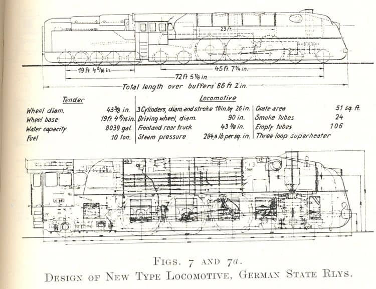
The two new type locomotives are laid out as 4-6-4 engines with 7 ft. 6 in.
drivers and rear cab. They are being built at the Borsig Works at Berlin,
and the first has left the shop and will undergo thorough tests at the Grunewald
Testing Dept. The front cabin type cannot be dealt with as the designs are
not complete. The wheels of the front bogie, those of the rear truck and
of the tender are 3 ft. 73/8 in. in diameter in order to keep
the number of revolutions within customary limits. The front truck has an
inside frame almost identical with the truck of German standard engines,
except that one of the two locomotives is fitted with spherical roller bearings
on all trailing wheels. Two helical springs have been added to the longitudinal
laminated spring so that the leading wheels may follow unevennesses of the
rail without overcoming any spring friction. The rear truck has an outside
frame to make room for the ashpan, and has also double spring suspension.
The wheel sets are interchangeable with those of the tender.
The boiler has been laid out for a grate area of 51 sq. ft., for a heating
surface of 2,938 sq. ft. for evaporation and for a superheater surface of
969 sq. ft. The boiler pressure was set at 284.5 lb. per sq. in. This pressure
still allowed for a copper firebox. The diameter of the boiler of the heavy
German Pacific, 6 ft. 3 in., could be retained considering the fact that
the test locomotive requires very slightly more power than the Pacific. The
number of smoke tubes (24) of 6¾ in./6 in. diameter is retained, and
the three-loop superheater of pipes of 1¼/7/8 in. The
number of fire tubes is 106 and their diameter 2¾ in./2ft
9/16in. The length of tubes has, for the first time in Germany,
been made 23 ft. or 8 in. more than the heavy Pacific. The smokebox is rather
long so that the feed-water heater found room behind the funnel; this enabled
the front part ahead of the funnel to be given a sloping top to deflect smoke
and steam from the cab windows. All fittings are of the standard type except
that some have been put closer against the boiler shell, so that the covering
will not interfere with the driver' s outlook.
The centre part of the ashpan, which, due to the bogie truck, is not quite
as spacious as might be desired. contains the main air inlet port and the
hopper bottom; as this air inlet would be in- sufficient for the grate, 68
in. wide, the ashpan has to have more air inlet ports on both sides outside
the frame.
The locomotive frame is of the bar type and 3ft in. in thickness. The smokebox
rests upon it by means of a welded saddle-like structure. To ensure smooth
running at highest speed the locomotive has three cylinders of 18 in. diameter
each and 26 in. stroke, working at angles of 120 deg.; all cylinders are
horizontal. Those outside, drive the second pair of coupled wheels, the inside
cylinder the first pair. All cylinders have independent Walschaerts gear;
the inside link motion has been taken off the second coupled axle by an inside
crank instead of an eccentric. The characteristics of the Walschaerts gear
have been altered to a certain extent to attain wider steam passages at short
cut-off and earlier admission so as to utilise live steam pressure for cushioning
the inertia forces of the rods at high speed. For this purpose the eccentricity
and the link have remained practically the same as usual, whereas the influence
of the crosshead upon the valve motion has been considerably enlarged. Thus
the valve travel is enlarged more than 50 per cent. and the steam passages,
especially during the exhaust period, are fully opened even at short cut-off.
Dr. Wagner then gave details of the braking arrangements and also of a number
of unusual features in the tender. A water supply of 8,000 gallons and 10
tons 0 f coal was considered necessary to run 200 miles without stop for
water and 400 miles without refuelling. These 45 tons of stores with the
requisite framing, tank and bunker, require five pairs of wheels; the first
two pairs are arranged in a bogie frame and the other three pairs are grouped
closely together in the main framing at the rear.
The discussion following the paper was opened by Mr. Gresley, and continued
by Mr. W. A. Stanier, Mr. J. Clayton, Lord Monkswell, and Messrs. Cyril Williams,
H. Holcroft, J. E. Spear, A. C. Carr, J. S. Tritton, W. Redpath, D. W. Sanford
and others .
Discussion recorded in full. The President: The first thing for me to do is to express our thanks to Dr. Wagner for coming over here all the way from Germany, for all the trouble he has taken in the preparation of this Paper and of the diagrams, and in converting his metric figures into figures which we can understand. I take that as a great compliment to the Institution. (Hear, hear.) The great thing is, of course, the substance of the Paper. I t is full of interest. There are so many members here who I am sure would like to ask questions and I have so many questions to ask myself, that I know you would only say: "I was going to ask that question, but the President forestalled me." So perhaps when you have done your questions I might do a little sweeping up at the end. Resume, illustration and diagram in Locomotive Mag., 1935, 41, 100-2
J. Clayton, (269-70).: As one of about 100 members of this Institution who had the great privilege and pleasure of visiting Germany in 1928, when we had such a wonderful reception from our German engineering friends, I cannot miss this opportunity of mentioning that one of the principal people amongst those who welcomed us then was Dr. Wagner. He came all the way from Berlin to Kassel to meet us and to see that we were well shown over Messrs. Henschel's works. In fact, he acted as one of the guides, and journeyed with us to Berlin to visit the German State Railway Works and their special experimental station at Grunewald. As far as the Paper itself is concerned, it should make us all very proud of the steam locomotive. It shows us that the last word, as so many would have us believe, has not been said with regard to it. We were interested in the Author's reference to the road engineer, who is apparently in Germany as big a trouble to the poor locomotive designer as he is in this Country. The engines described by the Author have not got beyond the experimental stage yet, but when the actual drawings appear-as we hope they will-in the Paper as published we shall probably know a good deal more about the details of their design. In passing, the Author mentioned in his last few words something about the metacentric of the engine and that it was not likely to upset so long as the speed was kept under something like 150 miles an hour. Nevertheless, there is always that other factor which may enter into the case, the condition of the road, but the margin of safety is a very substantial one. With regard to the boiler, may I ask what is the material of which the firebox plates and side water space stays are made? Also what curves can the engines such as he has described negotiate safely?
Wagmer's reply: Mr. Clayton mentioned the material of which the side
water space stays are made, but perhaps I may treat of all the boiler material.
For the boiler shell we have a chromium molybdenum steel, a very Iow alloy,
with not much molybdenum and with less chromium in it. The fire-box in this
type of locomotive is still of copper, and so are the stay bolts. But on
some other locomotives, in fact in all locomotives delivered during the second
half of 1935, we shall have steel fireboxes of two different types of mild
steel. This is a steel which has been made under indifferent gases; you know
the process of steel making in which steel is purified to a certain extent;
we call it "aged." Krupp has one patent for it, and there is another firm
in Siegerland.
Mr. Clayton's other question was which would be the smallest curve which
the locomotive could take? It is a curve with a radius of 180m., about 200
yards. On all points of our side tracks we branch off at this same
radius.
W.A. Stanier (pp. 270-1): It is with
very great pleasure that I accept the opportunity of saying a few words to-night,
because I look on the Author as one not only of German but of international
reputation. I have met him in America, Germany and England, and I always
regard the evidence of design that he shows as being of the very highest
rank. I had the opportunity when I was over in Germany two years ago of riding
on one of his new Pacific engines built by Krupp, and the way that engine
took curves at 70 miles an hour did not make my hair stand on end, for it
rode so well. I have therefore come to the conclusion that the Author has
some special way of springing engines which is superior to what I have been
accustomed to. I was very interested in the Paper he gave, and should like
to congratulate him on the many points that he has put before us to make
us think. I consider that what he has done in putting forward this design
represents a step that will make many of us review our designs and review
the conditions that we have to meet. Everything at the present time is for
speed. The general speed of the line has to be raised, and that means raising
not only the power of the engines but also their capacity for maintaining
high speeds. I was particularly interested in the way in which he has got
over his braking problems, but I should like to know how he manages to maintain
the efficiency of the brake on the bogie. Brakes on the bogie have been one
of my problems, and I have given up maintaining them and have taken them
off. I should like to ask why he needs braking on the bogie, seeing that
all his rolling stock is braked. It seems to me that, with the coupled wheels
braked and all the brakes on the rolling stock, there is not so much need
for a finicky little brake on the bogie.
His remarks on boiler design were very interesting, and I should like to
ask if he has used any special material in the barrel plates and firebox
plates to keep the weight down. He has a very powerful engine, and he speaks
of over 18 tons axle .load. For an engine of that power he seems to have
achieved something that is very much better than we have over here. He has
also not referred to the load gauge to which he can build. It seems to me
the advantages they enjoy of having no platforms in Germany and of bemg able
to build to something like 11ft. wide and 14ft: high enables the Author to
get a much better boiler efficiency than we can get with the English load
gauge. Wagner did not appear to give a formal response to Stanier,
D.W. Sanford (p. 271): There are just two questions
on which I should like the Author to give me a little more mformation. He
said that the brake percentage was 180 and that there was some automatic
means whereby that figure could be reduced as the speed dropped, no doubt
to compensate for the increase in the coefficient of friction between the
brake. and the wheel. Could he explain how that is done? . Is it some form
of accelerometer by which, as the retardation mcreases due to the increase
of friction the braking power is automatically diminished? ' Another point
is the suspension of the bogie. At the present time it is the practice on
some of our engines in this Country to take the weight at the side and not
in the centre, whereas. on the Continent, I believe, it is very largely the.
practice to try to take the weight in the centre of the bogie. We know from
experience that the method of having the weight on each side of the bogie
gives you a very good riding engine. I wonder whether the Author could tell
us whether in that particular engine the weight is taken on the centre of
the bogie or on the sides?
Wagner's response: Mr. Sanford asked me what we did to the brake on our bogie
trucks. We have had a lot of trouble with our bogie trucks for the last fifteen
years, but I do not think I have had a letter concerning them for the last
two years now, since we fastened everything on the bogie frame. That means
that all the brake arrangement was fixed on sprung parts, not on parts resting
directly on the journals, as is usually done on bogie trucks.
I cannot compare load gauges figure for figure, but I expect you know the
so-called Technische Einheit or T. E. gauge, which is in use practically
all over the Continent—the Berne unit; the locomotive is within that
gauge. Mr. Sanford asked me a very delicate question about the automatic
brake adjustment. We had delivered to us a casing which looked rather dreadful
and which had a lot of connections outside; one of these connections was
a flexible hose connecting to the journal of one of the rear bogie axles.
So there must be something like a governor inside this box! (Laughter.) I
have not opened it yet.
Mr. Sanford mentioned further the weight of the main frame riding on the
bogie truck. "We have in Germany—in fact in Prussia—put the weight
on both sides of the bogie truck for the last 50 years. That is what one
of the other speakers mentioned later—I think it was Mr. Tritton; he
asked me how we managed to do away with oscillation, and I understood that
what he meant was the oscillation of the leading bogie truck. (Mr.
Tritton:"Yes;'hunting,' we call it.") This is the factor that is playing
such a tragic roLe at present in some of the French locomotives. I am very
happy to say that we have never noticed oscillations of that kind, because
we distribute the pressure of the main frame on both sides of the truck.
That is the most effective damping you can have. The driver does his best
not to overgrease these parts, and so he makes the damping better than was
intended by the designer!
I expect you saw in the slide that we did not send the wheel load through
the leading bogie truck frame. We have the main frame and the supporters
on a platform, and underneath this platform is the balancing level and a
spring, both connecting the front and the rear journal of both the bogie
truck axles. None of the forces, therefore, go trough the frame of the truck
unless a spring breaks. Special provision has been made for this
occurring.
W. Cyril Williams (p. 271) Looking at these most interesting and highly-developed designs reminds one of the limitations of the orthodox type of locomotive, and I am therefore prompted to ask Dr. Wagner if an articulated engine has been considered. The Algerian Railways had just decided to obtain 12 Beyer-Garratt engines for speeds up to 80 miles an hour. The pressure will be 290lbs., and the tractive effort by formula 60,000lbs., with a 3,000 h.p. boiler by the O.C.E.M. formula. Perhaps such a type will open a fresh avenue for exploration in the future. The front tank could be aerodynamically arranged. Wagner's response: . Mr. Williams asked whether we had considered articulated engines. I suppose by his question he meant the Garratt engine. The Garratt engine, I think, has everything to gain as a tank engine and everything to lose as an engine with a tank behind.
E.H. Greg pp. 271-2): Unless I was mistaken, the Author said that the side wind did not matter. I have always understood that the side wind was the one that retarded the speed of the train by driving the train against the rail and the flanges binding on the rail; that a side wind was the important one and not the head wind. Also I think he said something about a side wind being resolved into two forces, that the side wind at right angles to the rail was entirely altered in its character by the speed at which the train is running. That is quite new to me to hear that a side wind has no effect on the retardation of the train. Wagner's response: Mr. Greg asked the question about a side wind. I am very sorry, but perhaps I made a mistake in explaining the mattter. I meant to say: The velocity of the train at fulll speed is something like 50 metres per second in the direction of the line. A fairly hard wind is something like 10 metres per second; that is what we call wind force 10—rather a nasty gale. The resulting angle of the wind is a tangent of 1 in 5, and in most cases it is even as low as 1 in 10, as in the ordinary 5-metre wind. That means that we have to consider the wind as far as the steadiness and the safety of the engine is concerned but we have not to consider wind as detrimental as it usually is to a slowly-moving engine. We only consider it as far as the resistance is concerned.
Julian Tritton (p. 272): I was hoping that the question of oscillation would have been mentioned by the Author. At these high speeds synchronous oscillation must be a difficult problem to deal with. I should like to ask him whether he took any special precautions in the designing of side control gear on the bogie, or an asynchronous system of springing, which would prevent oscillation building up to a dangerous amplitude. Also, would he give us details of the drawgear which he uses between the engine and the tender, and tell us whether this follows German State practice in adding part of the horizontal inertia of the tender to the back end of the engine as a controlling force? Wagner's reply: Mr. Tritton asked me another question about the tender connection. I know a good many tender connections that is one of the reasons why I have always been very conservatlve. We have, apart from two auxiliary bars, just one head bar—as heavy as it can be forged—and we do not make any fuss about it. It has two holes and a little lost motion in both. Besides we have two side buffers with very slightly inclined faces, and a spring in the tender pressing against both buffers. This spring tries to press the locomotive and tender away from one another, so that the slack in the very roughly cut main connecting bar is taken out. The spring acts like a balancer between the right and left buffers and—I think this is one of the good things we had in our Pacifics—has a pressure of 21 tons. That means that we can employ a two-cylinder engine of pretty high cylinder diameter, an engine which would otherwise give a very nasty longitudinal motion to the train; but it does not do this, because we take all the mass of the tender into the mass of the locomotive by employing a spring like that.
H. Holcroft (pp. 272-3): It is very significant
that the Author, after considering various alternative designs, has reverted
to the conventional design of locomotive, and in order to attain a normal
speed of a hundred miles an hour and a maximum of 110, has adopted a 90in.
driving wheel. When running at maximum speed .that represents about 420
revolutions of the wheel per rrunute. We know, however, from our experience
with modern engines having long travel piston valves, that that number of
revolutions represents the ultimate speed on the level at which an engine
can run when merely propelling itself. Owing to wire-drawing and back pressure,
the horse-power of the engine falls off until it is only sufficient to overcome
its own resistance; no further power is available for acceleration and an
ultimate speed is reached beyond which it cannot go unless a down gradient
is reached. It, therefore seems very bold to go in for a conventional type
of locomotive that will actually have to draw a train of five or six coaches
at this speed, in addition to propelling itself. I should like very much
to know whether any special consideration has been given to the design of
the cylinder ports and steam passages. A very large area for cross section
of ports, in order to keep the steam velocity down, is impractical, because
it adds so much more to the compression space. There is another way. to reduce
resistance which might be considered, and in this I think we should follow
the example of the internal combustion engineers and study the streamline
flow, so that steam from the steam chest reaches the piston and finds its
way out of the cylinder with the minimum of eddies. In that way we could
reduce our resistances and so improve the mean effective pressure and so
raise the horse-power at high speeds. I should like to know whether anything
of that kind has been considered in this present design, seeing that the
maximum speed of revolution of the normal locomotive is about 420 per minute.
In the ordinary way we get a maximum horse-power at about 250-300 revolutions,
and after that it begins to fall off, whereas in this locomotive it is desirable
to have the maximum horse-power somewhere about the speed at which it is
intended to run, namely, about 400 r.p.m. We know that in the case of small
high speed enclosed steam engines of modern design, such as are used for
steam rail cars, motor buses and other heavy road vehicles, the speed of
revolution is normally about a thousand per minute; and the maximum horse-power
is obtained somewhere about that speed, while the steam consumption per i.h.p.
hour not only compares well with that of a locomotive, but is actually even
better. If we were able to adopt a much higher speed of revolution like that
we could do with much smaller wheels and so reduce the spring borne weights.
With 90in. wheels plus axle, axle-boxes and springs, together with half the
weight of the connecting rods and coupling rods, the unsprung weight is very
heavy. It could be reduced considerably by putting up the speed of
revolution.
I should also like to know if any special consideration has been given to
the design of the coupling rods. At a speed of 110 m. p.h. the centrifugal
force must be very great, and it would be interesting to know what is the
throw of the coupling rod and whether any special section has been adopted
in the design.
Wagner's reply: Mr. Holcroft and Lord Monkswell specially asked about the
way in which we get the steam into the cylinders, and remarked how we got
it out again. Mr. Greg added the question: "Why not have poppet valves?"
Perhaps I had better start on the last question. The poppet valves to us
are an entirely open problem. We have a Caprotti engine for the last 20 years
we always had Lenz trial engines, which shows that we have not gIven them
up altogether. We have studied the poppet valve. problem, and I think that
the best valve I have yet found is the one mentioned by Mr. Gresley, the
Cossart valve, because that has not to be accelerated from a standstill in
the very moment steam is admitted. The acceleration begins earlier than the
steam admission. Take a system of movement that would make the whole Cossart
or Kerkhove valve move in a way which would give the smallest possible
acceleration, and therefore the slightest wear, and you have the link valve
motion. So for this reason I have always stuck, so far, to piston valves
and rather tried to improve their weak points. There is no saying that we
shall not some day or other see something better in the poppet valve, but
so far we have taken the following measures to improve the passage of the
steam through the cylindcr. We have cylinders of 450mm. diameter—that
is 18ins.—and we have made the valve chest 12ins. in diameter. Without
giving too much cubic clearance we altered the gear in the way I described
so that the pre-adrnission is very early; that does no harm in a very
fast-running engine, because there is still some residuary pressure.
Compression, in a year like this, comes pretty early; besides, we have formed
all the channels so as to make the velocity of the steam as low as possible
and to guide it in the direction in which it should flow. You remember, perhaps,
the patents of Professor Gutermuth, who tried to form the piston valve like
a nozzle. We cannot afford a nozzle, but we have done our best to guide the
steam. From our experience so far I can say that if some of you gentlemen
had the chance to ride on out locomotives and to see the back pressure, you
would see that we hardly ever exceed 1.5Ib., at full output. I hope that
in our later types we have improved on that; sometimes we get to half this
figure.
Mr. Holcroft spoke of running parts, and asked why we did not build an engine
with single fast-moving steam motors. I said in my Paper that we had considered
that, and we found from a preliminary calculation that an engme with three
independent drivers would not have stood much lower, in spite of the fact
that the drivers could have been made lower. Perhaps the day will come when
the individual drive will be absolutely necessary; that is when somebody
asks us to go beyond 140 m.p.h !
Mr. Holcroft mentions the coupling rods as well; I cannot show you the section
or the slides, though I am sure you would be interested in their design,
because a great deal of attention has been given to them. The section, of
course, is an "I" section, and I may just mention that the rods look rather
clumsy. The web is about half an inch thick, and the top and bottom flange
about five-eighths of an inch, and everything is heavily rounded off. I think
there is nothing to trouble us about the rods. By the way, we had a test
of the rods without really intending to in the yard of the makers. There
was a very large wet spot and the engine began slipping; the throttle stuck,
and just for a second the man could not shut it—and the engine did more
than 110 m.p.h. for that second!
Lord Monkswell (273-4): When
I was a boy at school and read W.M. Acworth's book on the Railways of
England —one of the best books I ever read in my life—it struck
me: "Why on earth should not we, all of us, go very much faster?" From that
day to this I have never found any real answer to that question. In my own
little way, I have been seeing quite a lot of what I consider to be an
exceedingly advanced type of engine—with that, I think, we all of us
here agree—M. Chapelon's engine on the Paris-Orleans line. I was very
much interested to compare, as far as I could, the design of the Author's
locomotive with that of M. Chapelon. The particular features that have struck
me include the extreme ease with which the steam is got through the cylinders.
The business about balancing the reciprocating parts and the strain upon
the rods does not seem to present much difficulty, but where the French design
seems to be so extraordinarily good is in just this point that I mentioned.
First of all, as I understand it, one has to get the steam as fluid as possible,
and in order to get the steam as fluid as possible one has to have exceedingly
high superheat. I was on one of these engines last summer, and the superheat
rose to 800°F. I should be very interested to know what temperature
the Author uses in his engines.
The next thing is the enormously big steam pipes. I should imagine that the
Paris-Orleans engines have steam pipes of about twice the section that engines
have usually been given. Perhaps the Author could tell me about that. Then
we come to the valves. I may say that I was enormously struck by the way
in which these valves worked.
In 1933 the Chemin de Fer du Nord allowed me to travel on one of their engines
fitted with ordinary piston valves, between Paris and Calais. I will just
take the Survilliers Bank: the engine was practically the same weight as
the Paris-Orleans Pacific which I accompanied in 1934, and the train was
the same weight; the weather was about the same, and the comparison was fair
in every way. In 1933 the Nord engine took a train up the Survilliers Bank
at an average speed of somewhere about 70 miles an hour with a cut-off in
the high pressure cylinders of 60 per cent. In 1934 the Chemin de Fer du
Nord had taken over some of the Paris-Orleans engines with poppet valves,
and a train of the same weight up the same bank in the same weather conditions
ran rather faster than the year before, with a cut-off in the high pressure
cylinders of only 40 per cent. It was perfectly astonishing the way in which
the steam got through the cylinders. I do not understand that there is anything
in the nature of poppet valves in the German engines, but perhaps the Author
could tell us what arrangements he has made for getting the steam rapidly
through the cylinders.
Then there is the question of the blast-pipe. There again, the double blast-pipe,
without any bother of variable arrangement, is an enormous simplification
and it seems to me to work in the most astonishing manner. If the Author
could tell us something about his blast-pipe it would be very interesting.
Wagner's reply: Lord Monkswell spoke about the 800° usually attained
by French locomotives. That is about the figure that we reach on our locomotives,
and we find, just like our French colleagues, that it is about the highest
figure we can do on our oil. In a few compounds we attain 900°. We found
that our simples could still be run at 800°F., and perhaps a little
more, but this temperature did not prove satisfactory in high pressure cylinders
of compounds. I am quite sure that we always put piston rings into the pistons
before starting, but sometimes we arrive without any!
A very interesting idea underlies the dimension of steam-pipes. We found
that it is very good for the locomotive to increase the admission pipe so
as to make it a sort of reservoir. We did it as well, and we also increased
the exhaust pipes so as to give us as slow a steam velocity as necessary.
I do not quite agree with Lord Monkswell about the importance of the cut-off
of the French locomotives in one case and the other: 60 and 40 per cent.
What he apparently had done was to run both locomotives at full boiler capacity,
and this is as much as could be done. When the admission temperature has
been 800° and has been run down to condensing point, and when the steam
has been expanded fully to atmosphere, that is all you can expect of the
cylinder, no matter what the distribution looks like.
Lord MonkswelI: Perhaps I may add that the water consumption corresponds
to the difference in the high-pressure cylinder cut-off. The water consumed
between Paris and Calais by the Nord engine was 28 tons, and by the Paris-Orleans
engine 22 tons, so it certainly looked as if there were very great economy.
Dr. Wagner: There may be many reasons for that. Either the piston valve
distribution was not m the best of order or the locomotive was not in the
best of order, or there' were four years of difference in the age of the
locomotives. All those things may have a hand in it—I do not know. (Lord
Monkswell: "No.") You would have to know all the details of the case.
The blast-pipe problem is very interesting. There is a great deal in the
design of the double blast-pipe. We are going to give it a trial and we expect
something from it. We have tried to go along on the same system without using
the intermediate nozzle. When the Finnish locomotive engineer Kylälä
(Kylala). came to me in 1923 we had our system ready and we had it put on
our first 20 locomotlves. Our system is different; it makes the stack as
wide as possible according to a very simple formula we have evolv~d for ourselves
from experience, making the exhaust as wide as possible and putting it down
as far as possible. The blast-pipe in our locomotive is between four and
six inches above the floor of the smoke box; that gives the upper cone of
steam as large a surface as possible. We shall have to see whether the Kylchap
brings us something extra or not; I cannot tell you, but I know that we raise
3¼ins. of water column in the smokebox by using a back pressure of something
like 0.5 to 1 lb.
W. Redpath (pp. 274-5) : As I understand it, the efficiency of the engine is increased somewhere in the neighbourhood of 16 to 20 per cent. by the fitting of the petticoats. One would like some information as regards the cost. I should also like to know what the thickness of the steel or any other material is that he has used for the petticoats, and also for the upper clothing of the boiler. I think these are all facts that will be of interest to designers here in connection with increasing efficiency of their locomotives in the way that the Author has indicated.
J.E. Spear (p. 275): It was particularly interesting to hear the Author mention that the engine was fitted with roller bearings on the leading bogie, and, it appeared from the drawings, on the trailing bogie as well. This of course is not surprising in view of the fact that the German State Railways have used roller bearings so extensively on their coaching stock, but I should like to hear whether he has considered roller bearings for the coupled axles either of these or subsequent engines, and to have his views in that respect. In answer to Mr. Spear, who pointed out that we had roller bearings on our bogie axles and not on. the coupled axles and that they were more trouble on bogie axles: we did it on purpose. It seemed impossible to us to have them on both rods and axle bearings, because you have to give one or both of them so much longitudinal tolerance that all the good that comes in from the bearing is taken away again by increased pounding. In uncoupled wheels, conditions would be better.
A Speaker (p. 275): May I just ask one question? Is it expected that the engines will be hand fired or mechanically fired? Dr. Wagner : They will be hand fired.
The President: (Gresley pp.
275-7) Actually Mr. Sandford is the
only one who has asked a question that I was going to ask: that was with
regard to how the air pressure is controlled proportionately to the speed.
That is, if you have a brake which is braked to the extent of 180 per cent.
of the weight between the tyre and the rail, as the speed comes down you
mentioned that you. have some device for reducing the pressure automatically
With the speed. I have seen devices of that sort but they have generally
been controlled on a time limit basis. If you have one on a time limit basis
and happen to have an emergency application when you are going about 12 miles
an hour, the wheels automatically pick up and you get a flat on your tyre.
No doubt the Author has some arrangement with the Westinghouse brake by which
the pressure is proportioned to the speed.
I am going to ask why he has such very large diameter driving wheels. Lord
Monkswell was telling us just now, as he has told us in the press several
times, about the wonderful speeds that are attained on the French railways.
I have travelled a great deal on French railways and know the French engineers
well. Many of them are old friends of mine. But I was surprised when M. Lancrenon
told me some years ago, after he had brought out his new tank engine for
working Paris suburban traffic (a tank engine with coupled wheels about 5ft.
in diameter and Cossart valve gear which provides for a very easy escape
of steam), that running between Creil and Paris one day, when one of the
big engines had the misfortune to break down, one of these tank engines was
put on and did the run from start tu stop in less time than they had ever
done it with the Pacific. The reason was, of course, that it was able to
get rid of the steam so easily. I do not think it is essential for excessive
high speeds to have a wheel of 7ft. 6ins. diameter.
Of course, Dr. Wagner, you know that when you come to England we criticise
you very freely and very openly, and you must take it all in good part. (Dr.
Wagner: "I am sure I do.") Another criticism I have to make—you will
think I am rather captious—is that you are talking of a 220-ton train,
and I do not exactly remember what the weight of the locomotive is, but it
is not far short of that of the train. It is a big engine with an 80-ton
tender, and the engine weighs 120 tons, making a total of 200 tons of engine
for 220 tons of train. That seems to me a great deal. I do not know what
your Diesel friends will say! You said in the early part of the Paper that
in order to help to reduce the weight, it is suggested by some engineers
that they should have what you called a "not very effective" combustion chamber.
That is a very interesting point. I notice in your design that you have not
provided a combustion chamber. During some trials we recently had in Paris
with the L.N .E. engines, at which one of the Est engines was also being
tried, I noticed one marked difference—the Est engine was better than
ours in the absence of smoke due to the enormous combustion chamber, it was
about 6ft. long. This was a very long-barrelled engine, and they had cut
their tubes down to a reasonable sort of length and used it to reduce the
weight at the back end. That, however, was not the main object; it was to
get more complete combustion, and I may say that directly they began firing,
within two or three seconds, the smoke entirely disappeared.
I cannot say the same of the other engines. Their explanation was that the
big combustion chamber tended towards the burning of smoke and gases. On
your engine I noticed that you have not even got a combustion chamber at
all but no doubt you have special reasons for your design. I am only mentioning
that because the French seem to be very keen on having large combustion chambers
and thereby of course, reducing the weight of the back end of the engine.
Another thing is why have you such a very small superheater—24
elements—on that great big engine? We have heard it suggested here that
one of the important. things is to get high superheat. I have 42 elements
in my engine, nearly double the number and do not get a very high degree
of superheat. As for 800°F. superheat, Lord M.onkswell may not be aware
that 15 years ago we were runnmg engrnes on the Great Northern Railway with
800°F. of superheat—the old Atlantic engines wIth. a 32 element
superheater; that is when they were working pretty hard. I often observed
over 800°F. indicated by the pyrometers; it may be suggested that the
pyrometers were not quite correct. I had them checked and rechecked before
and after, and they were correct. So there is nothing unusual in 800°F.
of superheat. French engines are runnmg at that, but anything beyond that
is too high and burns up the oil.
Reference has been made also to the double blast-pipe. I am. very interested
m this question and have had some very interesting and wonderful results
with it and I should be. interested to know why it is that you are not using
this so-called modern innovation. The double blast-pipe is not really modern
as it was made when I was at Crewe and I helped to make the engine that was
so fitted. It was a badly designed one and, of course, was a failure!
I wish, on behalf of all of us here and on my own personal behalf to express
our thanks to Dr. Wagner for coming. over here. It really is most complimentary
to this Institution that we should be the first as I think we are outside
Germany to hear details of his latest locomotive.
Dr. Wagner (p. 277 et seq), in reply: Let me first express
my heart-felt thanks for the kindness with which you have accepted my Paper.
You can irnagine what pleasure it was to me to read it to you and in your
midst and to ask for the strongest and strictest criticism that I could get
or expect In any circle of experts all over the world. We have attempted
to do something new in some ways, and we have laid ourselves open to criticism;
I am very grateful to you that your crrticism is so much to the point and
so valuable to the cause we all serve.
Mr. Gresley mentioned the Diesel engine. The comparison between steam and
Diesel is the problem of the day. I do not know what to say about this subject:
I think that we shall never be able in ordinary locomotlves to compare with
the Diesel as far as economy is concerned. Of course we cannot, but the one
thing .at which we can so far beat the Diesel engineers, and I thtnk we shall
have to keep up to that, is in always having just a couple of hundred horse-power
behind us.
The combustion chamber is another open question, but we have not used it
so far because we are afraid of the maintenance cost for stay bolts, and
of the lowering of the superheat in the present type of superheater. What
the President says is right, that in France the combustion chamber has proved
very useful for taking up the smoke, and so on, from a very rich but very
nasty smoking coal. In the type of firebox we have used so far we have reached
12 to 14 per cent. of CO2 without the combustion chamber. That
has always convinced me that the combustion was still all right. It may not
be so in the next case we touch upon, but so far we have had fair
combustion.
The smallness of the superheater is admitted but we have a different type
in our long boilers. You know a type with three loops and only one return.
The best recipe for gettmg a good superheat is to send dry steam into the
superheater. .One of the items of design without which none of our boiler
designers gets past me is that he has to answer. the question: "When the
glass is half full of water—whlch. means the ordinary running
condition—what is the velocity of the steam passing through the water
surface?" If the speed is more than one foot per second, he has to increase
his boiler diameter. So far as our tests have gone, we have found that moisture
of the steam is in that case within reasonable limits, below three or four
per cent., and that always gives a good superheat.
Communication from Mr. P. A. Hyde. (p. 283 et seq)
In regard to Mr. Spear's question as to why roller bearings had not been
applied to the driving axles also, I failed to catch the Author's reply clearly
but gathered th.at difficulties with side play governed the decision to stick
to plain bearings for the coupled axles. Taking this as being the reply,
I think that it is well that it should be recorded that some ten fast and
heavy engines, having all coupled axles fitted with rollers of two makes
are in service in the [United] States, and as far as the writer has been
able to ascertain by inquiry, the results are good, and in the case of three
engmes extraordinary.
The first engine put into service was the Timken 4-8-4 machine and this must
now have run a very considerable mileage. The.New York Central have had two
engines in service in what is the most trying service possible viz
the run between Windsor and Harmon some 960 miles at speeds reaching 75 miles
per hour, while loads run to as much as 1,400 tons. One engine with Timken
bearings had, when last I was given information on the subject, run 350,000
miles, while the other with S.K.F. bearings had run .380,000 miles. As this
mileage has been made in about three years there can be little wrong with
either layout.
The Delaware and Hudson has had two engines in service for about the same
time with satisfactory results, and a third, with Drivers S.K.F. fitted,
has also the big end and centre coupling rod eye fitted with rollers, the
results up to some 60,000 miles being satisfactory.
The Lackawanna has a number of engines at work and more being fitted, while
there are several other roads who have placed orders for similar equipment,
so that the total, built or building, cannot be far short of forty engines.
I would recommend, to those interested, a study of the report by the Committee
on Locomotive Construction, of the American Railway Association, on " Roller
Bearings for Locomotives and Tenders." In a table attached to this, which
gives the answers to a questionnaire on the subject, it will be found that
as far back as 1933 three lines were more or less in favour of the use of
rollers in coupled axle bearings, and to-day all of these, and at least two
others, have apparently satisfied themselves that they are a good thing,
as they are placing orders for a number of engines so fitted.
I believe that in a number of these engines over ¾in of side play is
given, under special control, in one or other of the boxes and that no trouble
results.
The main point is that at least three engines have made over 300,000 miles
in less than three years, and if this can be done there cannot be much wrong.
The Author's conditions may, however, differ very greatly from those in existence
in the States, and he is of course the best judge of them. It would, however,
be most interesting to have further remarks from him, especially on the facts
above stated.
Wagner's reply: I did not mention side play as a reason against using roller
bearings in coupled-wheel systems. What I mean is: The distancing tolerance
of two-wheel centres in the frame cannot economically be made less than ±
1/264 of an inch; the tolerance of two bores in a connecting rod is the same,
therefore by keeping inside these limits a difference in length between both
of 1/132in. may occur. This is more than the play in roller bearings, and
I am afraid it would strain the rod and perhaps cause the breaking of
rollers.
We are going to try that out in some ordinary locomotive, but I think that
no locomotive designer can be blamed for not putting roller bearings into
the first specimen of an extra fast running engine.
McDermid, W.F. (Paper No. 337).
Brakes for streamlined railway vehicles. 309-42. Disc.: 342-68. 4 diagrs.,
2 tables.
The Fifth Ordinary General Meeting of the 1934-35 Session was held
in the hall of the Institution of Mechanical Engineers, Storey's Gate,
Westminster, on Thursday, 31 January 1935, at 6 p.m. Mr. H.N. Gresley, President,
occupying the chair.
The following precis was published in
Locomotive Mag., 1935, 41, 44-5. At slow speeds the efficiency
of brakes is relatively high, and the train resistance factor becomes almost
negligible; but, particularly if it happens that the rail condition is greasy,
and therefore bad for braking, when a short train is braked at say from 65
to 70 m.p.h. probably as much as 6.5% of the retarding force will be due
to the train resistance, while for a long train at similar speed it would
amount to about 5%. Obviously any reduction of the resistance by stream-lining
the vehicles will to a like extent also render deficient the possibility
of its retardation. Thus, whilst much thought is devoted to a rapid accele-
ration at starting, in most cases, apparently, but little consideration is
given to new or improved means for making a rapid stop - even though stops
made quickly certainly reduce train running times.
Assuming that a train of some given weight is travellmg at 30 m.p.h. and
that at that speed the total energy in that train is represented by unity,
or .1; then, at 60 m.p.h. the total energy in that tram would amount to 4;
at 100 m.p.h. it would- be 11.1, and at 140 m.p.h. it would be 21.7 times
what it was at 30 m.p.h; thus it is clear that high speed calls for the highest
brake efficiency obtainable.
The author divided his subject into two main features, firstly dealing with
train - resisting quantities, and then examining the limiting fac- tors of.
the po:ver brakes now used; particularly emphasising differences in their
operating times. The determination of train resistances were dealt with under
five headings, summarised as. follows :-
(1) Journal friction, due to the rub- bing. of the journals on the brasses;
(2) rolling friction, due to the rolling action that takes place between
the tread of the wheel and the rail;
(3) track resistance, due to the compression of the track. as the train advances;
(4) flange action, occasioned by the side pressure of the flanges on the
rails ;
(5) air resistance and wind effects caused by the force of air on exposed
parts. This review follows the order adopted by Prof.
Carus-Wilson in his classical paper
read before the Institution of Civil Engineers in 1907. As to actual
braking the author referred to the investigations of Captain Douglas Galton,
on the L.B. & S.C.R. near Brighton in 1878, as well as those made on
the Lake Shore and Michigan Southern R.R. in 1909 and known as the Lake Shore
Emergency Brake Tests, and a third series carried out by the Pennsylvania
R.R. in 1913. In discussing the methods of braking, the author dealt first
with adhesion, and wheels skid- ding. The percentage of retardation, or brakes
efficiency when the results of an actual stop are being considered are covered
by the time taken to stop, the distance stopped in, and the initial speed.
The rate of propagation varies with the type of brake used. Assuming a train
of 20 passenger vehicles each 50 ft. long, has to be controlled, and that
an emer- gency brake application to full power has to be made. With the ordinary
vacuum brake, full power will become effective on the last vehicle in just
about 20 seconds after the first movement of the brake handle, provided each
vehicle has two 15- inch cylinders. If larger cylinders are in use, and they
should be, of course, the time allowance must be increased. "With the ordinary
Westinghouse brake, full power on the 20th vehicle will become effective
in just about 5 seconds, whatever the size of the cylinders may be.
Obviously, with both brakes, there is a period during which, on average,
the brakes are only partly applied. Perhaps about half the above times represents
this period of comparatively free runnmg. If the brake application has to
be made when the train is running at 60 m.p.h., or 88 ft. per second, the
free running times suggested corre- "pond with distances as under i-s- Ordinary
vacuum brake, free running for about 275 yards.
Ordinary Westinghouse brake, free running for about 100 yards.
In releasing the brakes, the last cylinder on the vacuum fitted train would
develop a piston movement in just about 30 seconds. Other factors of the
subject in which the author dealt at length were the friction of brake blocks,
the effects of pressure intensity, mean coefficients during stops, the effects
of temperature on friction of brake blocks, the effects of speed, the effects
of "hard- ness" in brake blocks, and the instantaneous coefficient of friction
at any speed.
Increasing the brake power by a greater leverage ratio is bad practice. The
effects of pin wear nount up leading to false travel of the brake iiston
and waste of power, while the "springing" If long levers aggravates the trouble.
In his conclusions the author asserted that the cylinder power of brakes
at present fitted to passenger stock in this country seldom exceeds about
90% of the weight of the vehicles; at speeds of 60 or 70 miles an hour this
amount of power is insufficient to enable full advantage to be taken, even
of the minimum wheel and rail "adhesion" when the rails are greasy, therefore
unnecessary risks are being accepted without justification- and this at speeds
which are quite normal. If really high speeds are contemplated, it appears
that in addition to using more powerful brakes, it would be advisable to
find out whether or not the "adhesion" factor can, in effect, be increased
by magnetic or other means. At present the brakes on a train of only ten
vehicles may take seven seconds to reach full power, and it may take ten
seconds to release the power. Pressure brakes on this ten-coach train,
electrically controlled, could be applied in two seconds and released in
three seconds. A difference of 12 seconds per stop, with stops necessary
at intervals of, for instance, 3 minutes, as in suburban working, represents
a useful saving of public time; but for faster trains, brakes quicker in
action, and more powerful than at present, are a necessity.
Factors which influence braking performance include journal friction; rolling
friction; track resistance; flange action; air resistance and the effect
of wind. Brakes are affected by adhesion and notably by wheels skidding.
Measures to evaluate braking efficieny (the rate of retardation) are examined.
The friction of brake blocks is influenced by pressure, temperature, speed
and hardness. There are several references to the work of Douglas Galton.
The wear of brake blocks is related to their hardness. Gresley
chaired the meeting and introduced the discussion (pp. 342-4) who considered
that the author had placed too great stress on cast iron brake blocks. He
noted that the German high speed trains, Flying Hamburger, were fitted
with electro-pneumatic brakes, slipper brakes, of the type fitted to tramcars.
These are cobined with Ferodo drum barkes, He commented on Michelin railcars
fitted with pneumatic tyres and commented favourably on their performance
on wet rails. See A4 class: Gresley contributed to discussion. "Streamlined"
implied high speed rather than streamlined per se.
Fifth Ordinary General Meeting of the Newcastle-on-Tyne Centre held at the
County Hotel, Newcastle, on Tuesday 19 March 1935, at 7.15 p.m.; chair taken
by G.M. Wells. E.D. Trask (p. 364) noted that Ferodo brake
blocks were then being used on surface lines, rather than just on underground
railways. G.M. Pargiter (pp. 364-5) noted that drum
brakes were fitted to the light diesel electric railcar and appeared to be
very efficient.
Place, P. (Paper No. 338).
Locomotive testing plants (with special reference to the Testing Plant at
Vitry). 380-406. Disc.: 406-15. 14 illus., 2 diagrs.
Eighth Ordinary General Meeting held in the hall of the Institution
of Mechanical Engineers, Storey’s Gate, Westminster, on Wednesdap 17
April 1935, at 6 p.m., the chair being taken by the President, H.N. Gresley
The following precis appeared in
Locomotive Mag., 1935, 41, 157:
The author described in detail the method of making tests and remarked that
they ensured accuracy within 5 per cent.
The wheels of the locomotive to be tested rest on rollers which turn with
them. The rollers are braked by suitable brakes. As a result the locomotive
is supported on the rollers as it is usually on the rails, and can exert
a tractive effort on a dynamometer to which it is connected by its drawbar
and pin.
The speed of the locomotive is varied by braking the rollers more or less
heavily.
The dynamometer measures the tractive effort corresponding to each speed.
The circumferential speed of the locomotive wheels is also measured, and
by integrating the tractive effort to the distance travelled the work done
at the tread is obtained.
Special instruments, such as pyrometers, pressure gauges, vacuum gauges,
combustion gas analysers, etc., are available for use in connection with
boiler tests and in preparing the heat balance sheets. Other instruments
are provided in connection with the tests on the engine and of these the
following general conditions may be noted.
A. Accuracy.-This depends upon-
The apparatus selected:
The way it is used;
Checking its accuracy and keeping it in good repair;
The method of making the tests; and
The operators.
B. Conoeniency
This depends upon-
The ease with which the instruments can be used;
The possibility of being able to record the results
The instr:uments standing rough usage, that is, upon their being strongly
made and easily kept in repair.
C. Caoacity
The test plant must be capable of testing the largest and most powerful
locomotives, not only at the present time but also in the rather distant
future.
The Amsler instruments are to very rigid requirements as the following will
confirm:
The maximum differences between the registered and the real values recorded,
are:-
Speed and pull, well below 1 per cent.
Work done, below 2 per cent.
Power, below 3 per cent.
The Pyrometers are exact to within 1 per cent.
The automatic smokebox gas analysers are very accurate but are used as indicating
instruments only. The heat balance sheets are based on analyses made with
the Orsat instrument.
The coal and the ashes are weighed on a weigh- ing machine to within 1 per
cent.
The ash is collected in the smoke duct in the roof; the velocity of the smoke
is low in this duct and the ash drops into it. It is then removed and weighed.
The cold water fed into the boiler is measured by graduated tanks. Water
lost at the injectors is collected and measured. The hot water actually injected
into the boiler is measured by piston meters correct to the thousandth part,
and this enables investigation of problems relating to injectors and feed
pumps.
Gresley opened the discussion (406-8): 'One of the
points that impressed me very much in the Paper was the Author's statement
in the last paragraph but one: "Tests repeated under identical conditions
at several weeks' interval on the same locomotive give results which only
differed very slightly, for example, by 5 to 10 h.p. on 1,500 h.p." That
means that if you put an engine on the plant and set the brake so that the
speed of the engine is, say, 120 kilometres per hour and you have a full
boiler pressure, the regulator open fully, and the valve gears arranged for
a certain cut-off, say 20 per cent. or 25 per cent., a month afterwards you
can put that same engine on the plant and you will get exactly the same power
recorded. You can do it over and over again, and, if you repeat the conditions
of the engine, you get the same power recorded on the chart. If you vary
the engine, make a slight alteration in the valve gear and a slight alteration
in some detail of the cut-off, and put the engine on the plant again, you
will get different results. As all the conditions have been constant under
the two tests, you can be fairly certain that the differences which are recorded
are due to the different fittings or the differences that you have made in
the engine. Thereby you can assess with almost complete certainty the value
of any new fitting which can be applied to an engine. If you have not got
a testing plant and you run the engine on the road, make an alteration to
it and run it on the road another day, you may get entirely different results.
If you run it on the road a third day, having restored the engine to its
original condition, you get further different results. The same engine running
day after day gives entirely different results owing to differences of
weather, of speed and of wind. All those variables are eliminated in
a testing plant.
Dr. H. J. Gough, F.R.S. (408): I have had
opportunities of inspecting and studying several locomotive testing plants
including those at Altoona, Illinois, Swindon and at Vitry I am of the opinion
that all the lessons and experiences available from previously existing
plants—including that established in
Germany—have been incorporated to produce at Vitry, what
is, undoubtedly, the finest test plant in existence. With the President,
I was privileged to witness tests at Vitry on the very latest British and
French types of locomotive. I consider that, should a testing plant be installed
in this Country—which I hope will be the
case—there are several further improvements which could
be introduced into the design, although, as the Author remarked, these would
concern detail rather than essential principles.
At Vitry I was particularly impressed by the Amsler dynamometer and recording
gear. I am acquainted with this type of Amsler design in other
directions—particularly in regard to testing
machines—and consider that their applications of the
hydraulic principle form examples of the highest craftsmanship. Their use
of the sphere for integrating purposes—as embodied in
the Vitry recording table—is a most interesting, and,
I believe, a novel development.
On the general question of the uses of a locomotive testing plant in this
Country, should one be installed, one aspect will, I hope, not be lost sight
of; I refer to the need for devoting much attention to research as against
mere routine testing. Although different types of engines would give different
results, it is not necessarily possible to estimate accurately the reasons
for such differences, because a number of variables are involved simultaneously.
I would like to see two plants installed. One could be devoted to routine
and development work of locomotives designed by Gresley, Stanier and others.
The other plant I would like to see devoted to research into locomotive design
from first principles.
C. A. J. Elphinston: The Author's Paper is very interesting and instructive.
I entirely agree that it is necessary to make scientific tests on locomotives
and to carry them out with the greatest possible accuracy, but I cannot
altogether agree that it is only possible to make such tests on a testing
plant. Here the speaker exhibited a slide.
The black points were obtained on testing plant in Russia, and the white
circles and the circles with dots in them were obtained from constant speed
trips on the track. These lie close enough together to enable a smooth curve
to be drawn. Here the speaker exhibited a second slide.
The points shown on this slide were obtained from 19 different locomotives
of the same class made by 19 different builders, tested on the same stretch
of road on various occasions during a period of six months. These results
are equally consistent.
W. A. Stanier (409) : I had the privilege of seeing the Vitry plant with
the President in January, and I was immensely struck by the great care that
had been taken to get accurate results. I. was particularly intrigued by
the very simple and Illgentous way by which the absolute accuracy of positioning
the engine wheels on the test bed road was ensured.
E. H. Greg: There is one question that I should like to ask. If such a testing
station as that at Vitry is to be constructed in this Country, I think it
will be advisable for such a plant to be made available not only for the
railway shops but also for the contract builders, and to receive their technical
and even financial support, as they, .of course, have to build engines for
gauges from, say, aft, 6lt1s. to sft. 6ins., and I should like to know whether
a plant of this description is capable of having the rollers and all the
various parts of the under-structure varied so that it can be used for very
narrow gauge engines, and also for very wide gauge engines, without a special
testing plant havtng to be built for each gauge. If a testing plant such
as that at Vitry is to be of universal adaptation in this Coun try, it 'will
certainly be necessary for it to be made appltcable to all gauges within
known limits.
Mr. J. G. B. Sams: Would it be possible in a testing plant such as that which
has been described to have some apparatus for measuring the hammer blow due
to the un- balanced revolving masses?
. Mr. H. Chambers: As one who has had some experience ~~Ith dynamorneter
car working, the diagrams posted 1 lustrate an ideal form of dynamometer
car chart, and the Continuity of the speed, drawbar, time, etc., is distinctly
a cOrnpliment to the stationary testing plant. With regard to the accuracy
of setting the coupled wheel on the drum; it occurs to me that in view of
the practice of testing locomotives by dynamometer car in their new condition,
and again at intermediate stages until shopped, under which conditions the
axleboxes would be worn, I should like to ask the Author whether any further
inaccuracy than I mm. on the centre of the rollers would be affected by the
side wear in the box. It seems to me that such a testing plant requires the
whole job to be of a research character, not only on the new locomotive but
on the engine in a certain worn condition, such particulars being very
valuable-indicating as they will any loss of efficiency due to the worn
conditions.
I should like also to refer to the Author's remarks on page 404 of the Paper,
where he points out the difference in the power absorbed by the drums on
a testing plant as compared with the tender drawbar. If such a plant is to
be adopted genet-ally, it seems to me that the time has arrived when a new
basis of comparison should be con- sidered, not per drawbar horse-power hour,
as the two methods of testing by stationary plant and dynamometer car al-e
not theoretically the same. Further, I think the time has arrived when the
variation in coals should be dealt with. Is it not possible with such a testing
plant to equate calorific value of coal to the power, say, for instance,
B.T.U.s per drawbar horse-power hour? ~~~~~
Sir Clement D. M. Hindley, It must be a matter of some surprise to people
in England, a Country which produced the locomotive and a country which has
lived very largely on coal and on steam prime movers, that we have to get
our information about this testing plant from our neighbours in France. We
know the history of that, of course, but I have come to the conclusion, after
hearing the Paper this evening, that perhaps we are fortunate in having delayed
a few years and given our friends the opportunity of putting through an
experiment which when the time comes to establish a plant of this kind in
this Country, will be of most extraordinary value.
I have had an opportunity. of . ~earing. what th~ President reported in regard
to his VISit to Vitry , and do t~ink that this is a matter which should intere~t
a large~ public perhaps than can be found 111 the InstitutIOn '. hope therefore
that there will be opportunities of making" " h h '1 com- this information
widely known so t at t e ra i way parries in particular may prick up their
ears and see what great scien.tific advances may be made by a proper testing
of locomotl:ves.
There is one other remark I should like to make. If such a plant had been
in existence in this Country in years past, I think the manufacturers of
locomotives here might not have suffer~d so severely in competition with
foreign countries. It will be a very important factor in the export trade
of locomotives from this country in the future. Mr. H. I. Andrews: Anyone
who has worked on a test plant for any length of time cannot fail to be greatly
im- pressed by the s~ate~ent in the ~uthor:s. Paper that at Vitry the locomotive
IS actually set 111 positron on the plant in half a day. At the plant with
which I have been con- nected, that of Illinois, generally considered to
be the finest test plant in America, several days are required to instal
the locomotive on the plant, this representing a considerable proportion
of the total cost of carrying out a test. I think the other members will
agree with me when I suggest that this comparison speaks volumes for the
care which has been taken in the design and organisation of the plant at
Vitry.
Sir Hugh Reid, Bt., C.B.E.: I have listened with great delight to the very
able paper which M. Place has read, but, as an amateur photographer, I was
still more interested .in .the. magnificent photography and the moving arrows
indicating all the different stages, even showing the progress of the oil
through the apparatus. I have had some little experience of a testing plant.
Wh~n we built the turbine locomotive, we rigged out a testmg plant to enable
us to use it for other than the 4ft. 8tin. gauge. We arranged a series of
wheels along the shafts so that we could test even down to zft. 6in. gauge
on the same plant. We found the installation very useful, ?ecause the locomotive
happened to be a condensing ~OCOmOtlve and we wondered what the condensing
plant on It .was able to undertake. We therefore took a London, ~ldland.
and Scottish boiler and added its output to the ocomotJve boiler on the turbine
locomotive, and in that Way we .were able to test the condenser very
satisfactorily. . I wish the President all success in his campaign. It nl
not only for his own railway that he wishes to have this r a~t,. b~t for
the progress of scientific locomotive design n rttam and for the Dominions.
si The Author's replies: Mr. Elphinston claims that a o~g~e power curve can
be drawn, using all the values a1ned when making tests at the test plant
and during .
Murray, G.L. (Paper No. 339)
A system of limit gauging controlled by colours, with special reference to
valve gear maintenance. 418-30. Disc.: 430-43. 3 illus., 8 diagrs.
Paper presented in London on 3 January 1935. Intended for an illiterate
workforce in the Sudan. Suggested that "go"/"no go"" gauges for valve gear
maintence had originated at Horwich Works in about
1920. Locomotive Mag., 1935,
25, 27: .After dealing with the development of limit gauging for
the production of parts which have to be interchangeable, the author proceeded
to explain his system of identifying and using such gauges by colour methods,
particularly in countries where European letters and figures have no significance
in workshops employing natives. He described at length the system in use
in the shops of the Sudan Govt. Railways for analysing and investigating
the condition of the valve gear on the locomo- tives in service. The routine
for valve gear repairs and the manner in which the control of the gauges
functioned was next described. After the valve gear details are laid out
on a bench, an inspector using a coloured step gauge ascertains the sizes
in terms of colour to which the various holes should be finished. As the
correct colour size of each hole is ascertained a disc of the corresponding
colour is attached la. each valve member adjacent to the hole, by means of
a wire, which is lead sealed by the inspector. For a running hole a circular
disc is used, and for a fixing hole an oval disc, and these shapes match
the recesses in the ends of the plug gauges. When grinding any particular
hole the operator uses the coloured plug gauge which corresponds with the
coloured disc attached to the hole concerned. As the various members are
completed they are returned to the bench with the coloured discs intact.
When the holes and pins are passed for size a record for reference is made
on the Motion Sheet, and last of all, the lead seal attaching the colour
disc to the hole is broken and the disc handed back to the gaug·e room
for future use. The system has been extended to other railway details, and
has been applied to other fields of industry.
Journal No. 126
Clarke, C.W. (Paper No. 340)
Notes on the design and equipment of a modern railway dynamometer car, from
an operating point of view. 447-76. Disc.: 477-96.
Based on experience gained on the Great Indian Peninsular Railway
and other railways in India of a car which was originally described in
Paper No. 282.
Rudgard, H. (Paper No. 341).
Motive power matters. 497-519. Disc.: 519-36. 7 illus., diagr.
Compared straight sheds with round houses: latter are more difficult
to build and maintain and are vulnerable to failure of the turntable/s. The
foreman's office should give a clear overall view. Lighting. LMS standard
pit. Locomotive availability. Repairs. Availability of tools. Drop pits for
coupled wheels. Periodical and mileage examinations. Periodic maintenance.
Washing out. Hot water system saved time, but required fixed equipment. Reporting
repairs. Stores. Costing. Shed staff. Lodges or barracks. Oil. Casulaties.
Shopping. Coaling plants. Mechanization. Ash removal plants. Sand furnaces,
including Kelbus sand dryer. Water sofenting. Breakdown work. Discussion:
G.S. Bellamy (519-20) asked about the provision of powered turntables and
whether mechanized cleaning had been implemented. D.W. Sanford (520-1) commented
on the change in the construction of brick arches: slab bricks had been
introduced. He was critical of throwing out the fire which led to rapid cooling
of the firebox. E.S. Cox (521) considered that there was a lack of mechanical
training for footplate crews. Wilkins (521-2) spoke about grease lubrication
and shed heating. Sidewell (522) intervals between washing outs and fire
dropping. Stephens (522) argued that hot water washing out reduced the stress
on the boiler and firebox. Geary (522) asked whether training was supplied
to depots which operated Caprotti fitted locomotives. R.S. Hall (522-3) noted
that a form of mechanical cleaning was applied to locomotives entering works
for overhaul on the Federeted Malay States Railway..
Arnold, Conway (Paper No. 342)
Practical vacuum brake maintenance on goods vehicles. 537-51. Disc.: 551-6.
3 diagrs.
Presented in Manchester on 19 February 1935. Based on experience gained
in India between 1919 and 1928 during a transition period from partially
braked to fully braked freight trains.
Journal No. 127
Carr, A.C.
Presidential Address. 570-94 + 2 folding maps.
Thec following appeared in
Locomotive Mag., 1935, 41,
308-9 and is much better than KPJ's meagre effort: At the opening meeting
of the 1935-6 session held at the Institute of Mechanical Engineers, on 21
September 1935, the retiring President, H.N. Gresley, C.B.E., introduced
the new President, A.C. Carr V.D., to the members and formally handed over
the chairmanship. A numerous company were present, and . Carr, after thanking
the Institution for the honour they had given him, recalled the indebtedness
to the retiring president and the council for the support the Institution
had received from Gresley during his year of office. The thanks of the
Institution were also expressed by Major C. E. Williams, C.B.E., and J. Clayton,
M.B.E.
Mr. Carr then gave a very interesting and entertaining address on the Indian
railways, their locomotives and rolling stock, with special reference to
the Bengal-Nagpur Railway, with which he was so intimately connected.
There are 42,953 route miles of railway in India of which 21,132 miles are
of 5 ft. 6 in. gauge, 17,644 of metre, and 4,177 of 2 ft. 6 in. or 2 ft.
gauges, whilst only 3,684 miles of the total are double track or more, so
that the bulk of the traffic is worked over single lines of railway. He rendered
many excellent details of the large railway systems of British India, and
emphasized the long distances separating the chief cities and the convenient
connections made by the trunk railways to suit the travelling public, quoting
.the distance between Bombay and Calcutta, via the B.N.R. route as 1,223
miles, whilst via the E.I.R. it is 1,349 miles. Other examples are Bombay
to Madras, 794 miles; Calcutta to Madras, 1,032 miles; Bombay to Delhi, 957
miles; Calcutta to Delhi, 902 miles; and Madras to Delhi, 1,351 miles.
After mentioning that the number of locomotives operating the Indian railways
comprises 9,248 steam engines, 75 electric locomotives, 40 rail motor cars,
31 steam coaches, 4 internal combustion engined cars, 117 electric motor
coaches, 20,753 coaching vehicles, and 223,830 goods vehicles, while the
staff employed numbers 701,362 of whom 3,906 are Europeans, Carr gave some
figures regarding the consumption of coal, pointing out the difference in
price per ton on various railways, ranging from 7s. to nearly 30s. per ton.
On those railways favoured with cheaper coals, Carr very much doubted if
oil engines or electric railways would supplant steam locomotion for many
years to come—one telling figure he gave being the variation In price
of oil fuel during the last eight years In India. It bad gone up by approximately
25% in cost, whereas steam coal had barely increased 11%.
With illimitable supplies of Indian coal available at comparatively cheap
rates for those railways adjacent to the coal fields, any general use of
Diesel locomotives he considered remote, but on railways where, water troubles
2Je acute and coal is expensive, and for shunting purposes, and where flexibility
and interchangeability for main line work are not of great importance, perhaps
a likely field might be found for their use.
The general adoption of superheat for locornotives was noted, and Carr recounted
some of his experiences on later engines with poppet valve and rotary cam
valve gear, both of which appeared to be promising. The provision of electric
headlights on the mail trains, too, was commented on, and it was mentioned
with some satisfaction that now British makers are supplying this plant.
An effective and continual improvement in the daily mileage of locomotives
was also noted. The average figure for all the Indian broad-gauge railways
for 1933-34 was 107 miles per day per engine in use, and 10.4 miles were
run per engine per hour during the same period. These figures compared with
those published for the L.M. & S. Railway, respectively, 110.5 miles
per day, and 9 miles per engine per hour for 1934. A total engine mileage
of the broad-gauge in India of 127,000,000 miles, approximately, would require,
said Mr. Carr, 3,250 locomotives in use out of a total of 5,670- or, say,
58 per cent. On the L.M. & S. Railway the same figure would be 66 per
cent.
Bogie coaching stock for all classes of passengers is now in general use
on the broad-gauge railways, and 94.5 per cent. of the coaching stock is
equipped either with electric light or gas. Gas is, however, gradually being
displaced by electric light. A novel application of electric lighting on
some railways is the provision of exterior lights on the coaches, controlled
by the guard, which floodlight many of the dimly lighted roadside stations
when the train is standing at the platforms. The fitting of vacuum brakes
to the goods stock was also referred to.
In concluding his address the new President illustrated his interesting remarks
by a number of excellent lantern slides, which showed not only fine views
on the railway but typical items of locomotives, rolling stock and goods
trains, including some heavy examples of the latter used for the coal traffic
on the Bengal-Nagpur system.
A vote of thanks to Mr. Carr was proposed by Mr. W. J. Tomes, the late chief
mechanical engineer of the East Indian Railway, and seconded by H. Kelway-Bamber,
past President of the Institution.
Willcox, S.T. (Paper No. 343)
A method of forecasting engines for heavy repairs, with reference to stores
stock. 595-603. Disc.: 603-8.
Paper read at Perambur, India, on 23 November 1934.
Black, A.H. (Paper No. 344)
A review of tool room practice on an Argentine railway (yesterday, to-day
and to-morrow). 611-42. Disc.: 642-71.
Journal No. 128
Topham, W.L. (Paper No. 345)
The application of oil as a fuel for the modern locomotive. 684-730. Disc.:
730-59.
Paper presented at the workshops of the Buenos Aires Great Souther
Railway at Bahia Blanca in Argentina on 28 June 1935. .Although mainly concerned
with the application of oil firing on the Buenos Aires Great Southern Railway,
the author does survey earlier developments in Britain: the Holden patented
apparatus is described together with its application on the Great Eastern
Railway; by J.F. McIntosh on the Caledonian Railway during the 1912 coal
strike; by Coey on the Great Southern & Western Railway in Ireland, and
"Malcolm of the GNR of Ireland [sic]". The Scarab system was used on the
Highland Railway Clan class (the performance of one so fitted is described.
The Scarab system was also used on the LSWR, GNR (Gresley), GCR, NBR and
Metropolitan Railway. The Mexican trough system was used on the Midland Railway,
and by the LMS during the 1926 General Strike.
Cox, E.S. (Paper No. 346)
Locomotive wheels, tyres and axles. 761-87. Disc.: 787-828: 1936, 36.
807-32.
The Second Ordinary General Meeting of the 1935-36 Session was held
at the Institution of Mechanical Engineers, Storey's Gate, Westminster, on
Thursday, 31 October 1935, at 6 p.m. . A.C. Carr, President, occupying the
chair. The following resume was published
in Locomotive Mag., 1935, 41, 347-51
Cox dealt with the main practical points which occur m the design,
construction and maintenance of these important components in the making-up
of a locomotive, and, from the point of VIew of safety, almost the most
important, smce .any failure can be attended by most serious results.
Wheels. The old hand-forged wheels gave excellent results but this type has
long been superseded by the steel casting, the only variant being a form
of cast iron centre which was used on the freight engines of the L.&
N.W.R. A recommended form of wheel rim is of triangular section, as this
grves better resistance to flexing between the spokes, due. to impacts arising
from blows received as the engine passes over rail joints, points and crossings.
Another point concerns the balance weight which, in the past, was usually
cast solid with the wheel centre. This is open to two objections one being
that at the point of junction of the wheel rim and the balance weight there
is an undesirable change of section, which is a point of weakness when the
tyre is shrunk on—and the other is that however carefully the amount
of metal required may be worked out, it is found to be incorrect due to vagaries
of casting. Some surprising results have been found on the wheel balancing
machine when wheels, thought to be accurately balanced theoretically, have
been tried over. If the weight worked out theoretically is deliberately kept
on the high side, portions can be drilled out until the correct balance is
obtained but the better practice is to build up the balance weights in the
form of two plates riveted together embracing the spokes, the cavity between
being filled with the correct amount of lead—a mixture of 95 per cent.
lead and 5 per cent. antimony being satisfactory.
Another point to give the tyre as even a support as possible throughout its
circumference, is the disposition of the wheel spokes at the point where
the crank pin boss comes nearest to the rim. It is often the practice to
have a spoke lying along the continuation of the axis joining the axle and
the crank pin centres. This spoke, necessarily shorter than its fellows,
will make the rim more rigid at that point, and it is preferable to dispose
the spokes of equal length, one on either side of the axis referred to.
The author then dealt with the wheel centre, and after outlining the defects
which may develop, and the methods of finding strain arising from blows against
the flange set up by the track, and of checking cases of wheel wobble due
to a bent axle, he empha:sized the importance of a good finish on the rim,
which the advent of titanium molybdenum tipped tools has made less difficult
to obtain. Corrosion takes place between tyre and rim in service, and forms
starting points for minute flaws. It is combated to some extent by smearing
oil on the rim before it is lowered into the heated tyre before shrinking.
An experiment has been tried of inserting a thin copper ring, 1/20 in. thick,
between the two elements. The wheels so fitted are still in service after
three years, and so far there has been no sign of movement or spreading of
the copper ring. It remains to be seen when the tyre reaches the end of its
life and is taken off, what the effect has been on the sur- faces.
Tyres. Records of the Midland Ry. show that m 1877, tyres were made from
crucible and Bessemer steel and solid rolled iron without any definite mechanical
or chemical specification being laid down. The former was only introduced
in 1887, and the latter in 1892. The present specification for tyres on the
L.M.S.R. is as follows:-
|
|
Diameter of bore of tyre. |
|
|
Over 5ft. 11 in. |
4 fr. 11 in. and under 5ft. 11in. |
Under 4ft. 11in. |
Tensile strength tons/sq. in. |
50-55 |
50-55 |
56-62 |
Elongation per cent |
18-15 |
18-15 |
13-11 |
S. or P |
0.04 |
0.04 |
0.04 |
Oil treated.
Heat treatment is left to the manufacturers so long as the tests are
complied with, but where oil- treatment is specified, the tyres are quenched
in oil and subsequently tempered to a visible red heat (600-650°C.)
for a sufficient length of time to ensure that the rolling and hardening
stresses are relieved.
Steels with oonsiderably higher tensile strength than the above are available,
and their use would certainly be attended by greater resistance to wear,
but in view of the flexing to which the tyre is subject, good ductility is
the most necessary requirement.
The method by which tyres are heated and shrunk on to the wheel centre is
simple and familiar to all. What is not so simple is to determine how much
shrinkage is to be allowed in this process, because to take two obvious extremes,
if too little is allowed, the tyre will not grip the centre sufficiently
and will come loose in service, whilst too great a shrinkage will either
deform the wheel centre if the latter is of weak design, or if it be rigid,
an excessive initial stress will be set up in the tyre.
Actual figures for shrinkage allowance vary considerably. The L.M.S. allowance
is D/l,200 + .005 in. where D is the diameter of the wheel centre. This,
converted to a plain fraction, gives an allowance varying from D/l,030 with
a 3 ft. wheel centre to D/l,120 with a 7 ft. wheel centre. This is a considerably
lower allowance, in the larger diameters at any rate, than is used on some
other British main lines, but no trouble has been experienced with loose
tyres arising therefrom.
As on wheel centres, the best possible finish is required in the bore of
the tyre and all sharp edges should be carefully avoided by small radii.
With the new titanium molybdenum tipped tools a finish in the bore comparable
to grinding can be obtained, and on good machine's in actual practice a working
tolerance of 0.003 in. on large tyres, to 0.005 in. on small tyres is allowed.
This is always a plus tolerance, as the spill gauge for measuring the bore
is set to give nominal shrinkage, and, if it can be inserted in the bore
at all, the clearance must be in the plus direction, making for a slightly
lower actual allowance.
When a new tyre is to be fitted, an accurate measurement of the outside diameter
of the wheel centre is taken, and this is transferred, less the shrinkage
allowance, to the spill gauge to which the tyre is bored.
Unless great care is exercised here, considerable errors can creep in, as
even a slight degree of spring in 'a caliper gauge on a large wheel will
give an incorrect diameter. The caliper gauge used should be light but very
rigid, and should also be direct reading.
After describing the main types of tyre fastening, both of the ring and stud
forms, the problems of tyre failures and their causes were detailed. The
best recipe for freedom from failures is to employ tyre material of good
ductility, gauge as accurately as possible to avoid errors leading to excess
shrinkage, choose the lowest shrinkage allowance compatible with avoiding
loose tyres, machine the mating surfaces with the finest finish commercially
obtainable, put a definite radius on all corners, give adequate support to
the tyre by a rim of triangular section, and make this support even all the
way round by the avoidance of cast-in balance weights.
Axles. The straight axle on a locomotive is a very reliable component and
breakages are infrequent, being more prone to occur, if anything, on axles
having outside journals. Apart from these latter, such as do occur are mainly
due to faulty material, often to some old and obsolete specification, or
to the effect of hot bearings, where the white-metal and brass have become
fused and run away, leaving some portion of the steel box to act as a cutting
tool and sever the axle.
Axles are now usually made with a tensile strength of 35/40 tons per square
inch, the elongation being not less than 25 per cent. with 35 tons, or 20
per cent. with 40 tons. Where weight saving is of importance, some advantage
may be obtained from boring out the axle, and many engines are running
successfully with such a hole down the centre of each coupled axle.
Pressing on of axles on to the wheel seats is done by hydraulic press. No
pressing on allowance or pressing on lubricant is specified as a rule, but
it is required that a pressure of 10 to 12 tons per inch of wheel seat diameter
shall be obtained in the process. This method of specifying allows a considerable
difference to occur in the nature of the fits. If the metal on the mating
surfaces is not to tear and seize in pressing on, some form of lubricant
is necessary, but given identical conditions of machining and pressing in
allowance, great differences in pressing in loads are obtained with different
kinds of lubricant. This is known from shop practice in a general way, and
recent experiments have been carried out by R. Russell at Glasgow Royal Technical
College on tramway wheels and axles with a large variety of lubricants. It
has been ascertained that, other variables being kept constant, there is
almost 300 per cent. increase in pressing on tonnage obtainable between tallow
and 10 per cent. white lead on the one hand, and Bayonne engine oil on the
other. Rape oil with 2 per cent. "oildag" cames about half-way up the scale.
One lubricant which is considered satisfactory in locomotive work is a mixture
of mineral oil and superheater oil with a small percentage of "oildag," which
latter is a colloidal graphite preparation, but the main object in selecting
such a lubricant for shop purposes has been to get as smooth a pressing on
as possible consistent with obtaining the right tonnage.
An interesting point arises regarding the fitting of axles into the wheel
seats. The axle being larger than the hole by the amount of the pressing
in allowance, a slight lead in is necessary to get it to enter the hole at
all. Then in pressing in there appears a tendency for a slight flow of metal
to occur. The effect where a parallel axle is pressed into a parallel
hole is that the radial pressure is very uneven along the length of the
fit, there being an initial portion of low pressure where the axle
was given lead in, followed by a portion where the ut is good, but in the
last section of the length the radial pressure may be very light in the portion
which entered the wheel last. When such axles are pressed out, it is often
found that they have been mating satisfactorily over only a proportion of
the total length.
Something better than a parallel axle in a parallel hole appears to be called
for. Any form of tapered axle and hole is undesirable in that a taper fit
is self-releasing once the slightest movement has started, and there is on
an axle no element corresponding to the riveting on a crankpin which will
resist initial side movement other than the frictional resistance set up
by the fit. A satisfactory compromise would appear to be to make the hole
in the wheel parallel, whilst the axle has a very slight taper, say 1 in
500, the smallest end of course entering the hole first. The hole is bored
below nominal by the amount of the pressing in allowance, and a slight lead
in is allowed for about 3/8 in. inwards from the mouth. The axle end is nominal
diameter at the end which enters the hole first, but a small radius, say
1/16 is put on the corner and this allows the axle to be introduced into
the hole. As the axle is pressed home it will be seen that any tendency for
the metal to flow is compensated for by the increasing diameter due to the
taper, and the result is a good sound fit over the whole length.
Crank Axles. As the confines of the British loading-gauge compel multiplication
of cylinders to be resorted to in the higher powers, the crank axle continues
to be a highly important component.
It may fairly be said that in the battle between the solid and the built-up
types, the latter has won the day, and it is almost universal practice in
this country to equip modern engines with this type, unless the power output
be comparatively low. The reason for this may be outlined as follows:-
(1) More reliable for high powers.
(2) Rarely break.
(3) Cheaper in first cost, the ratio being very nearly as 1 is to 2.
(4) Indefinite life, as one part after another can be renewed, and in consequence
a defect in one part does not require the whole axle to be scrapped. Built-up
axles are, however, admittedly expensive to maintain. In giving a brief resume
of the theory, indicating the different stresses involved and how they are
allowed for in the design, some of the forces involved are incalculable in
the present stage of our knowledge. Of those which can be calcula- lated,
the crank axle is subject to the following:-
(1) Direct piston thrust.
(2) Forces due to coupling rods.
(3) Weight on journals. Nos. 1 and 2 combined, induce a horizontal bending
moment, and No. 3 causes a vertical bending moment. These are worked out
separately by graphical methods and combined to determine the stress produced.
The effect of the vertical bending moment is small in relation to the horizontal.
It is also necessary to consider the stresses set up by torque, the maximum
value of which is obtained for the portion of the axle between crank and
wheel when the coupling rod crank on that side is at right angles to the
coupling rod; i.e., when the coupling rod on the side in question is transmitting
the whole of the power to the remaining coupled wheels.
The bending arid twisting moments are finally combined to .gIve the maximum
stresses in the axle. In order to allow for the other forces which cannot
be calculated, the maximum stress is kept low, usually not above 5 tons per
square inch. In the sohd a:x;le, the tendency to bend and twist, due to the
vanous causes mentioned has to be resisted by the toughness and elasticity
of the matenal itself, and when this is insufficient to begin with, or is
rendered so by a sufficiently high number of reversals of stress, flaws begin
to appear at the weakest points and these continue to grow thereafter with
greater or less rapidity, terminating occasionally,. if growth is sufficiently
rapid to outstnp exarmnation, in breakage.
In the built-up crank the forces outlined above have to be resisted by the
shrinkage fits, and when these are insufficient for any reason, looseness
occurs. Additional stresses are also set up in this type due to the shrinkage
itself. The stresses set up In the web material surrounding the fit are usually
calculated from Lamé's thick cylinder theory, and expressions can
be obtained for the radial pressure due to any given allowance and also for
the hoop stress in the layer of material in the w~b immediately adjacent
to the jointure.
Solzd Crank Axles. The specification of the ma:terial usually calls for a
tensile strength of 28-32 tons per square inch with an elongation of not
less than 25 per cent. Carbon is not to exceed 0.22 per cent. and sulphur
and phosphorus 0.04 per cent.
Buzlt-up Crank Axles. The methods used in building up these axles were described
in Shawcross's paper read in 1926. Each works
has slight variations in the methods used in assembling. In some cases the
whole web is heated prior to inserting the shafts and pins, whilst others
will only heat the hole locally by means of an internal gas ring. Then again,
the assembly may be allowed to cool down naturally, or a jet of water may
be employed. It cannot be said that the results arising from these variations
in methods of construction differ very much, and of much more importance
in the life of the crank are the considerations which follow:-
As the crank axle relies for good service prin- cipally on the .grip of the
various parts one on the other, the shnnkage allowance is of the greatest
Importance.
Allowances at present in use have been arrived at by practical trial and
error in the shops over many years, and a very common allowance to-day 1;
0.003 in. per inch of diameter.
Calculated by the usual method the hoop stresses in the layer of web material
adjacent to the jointure are of the following order:-
|
|
Shrinkage allowance per in. dia |
|
|
003 in |
.0025 in |
.002 in |
Shaft 9½ in. dia. in web tons per square inch |
24.5 |
20.4 |
16.3 |
Pin 8½ in. dia. in web tons per square inch |
24.8 |
20.8 |
16.5 |
There is here a point of considerable interest in that the stresses
at this point are very high, bor- dering on' the yield point. The yield point
of 32-38 ton material, of which most of the existing cranks are composed,
is about 19 tons per square inch, while with 40-45 ton material having a
carbon content of 0.4 to 0.45 per cent., which has been more recently adopted
for webs, the yield point is about 21 tons per square inch. In actual practice,
however, even after big mileages no cracks or incipient flaws are usually
discernable on the surfaces of the parts which have been subjected to this
treatment, and a fracture arising from a fatigue flaw starting in the bore
of a crank web is practically unknown if the material be sound.
It is therefore from present knowledge and experience difficult to fix an
upper limit of permissible shrinkage allowance, but it is easy to visualise
that a point could be reached where the elastic limit would be passed, and
the material of the web would be in a condition of permanent set in which
it would refuse to grip the shaft. Another factor to be considered is the
ratio of diameter of shaft to width of webs, and in engine, having large
inside cylinders, if it is desired to give reasonably large bearing surfaces,
the width of the web is very restricted. Expressed as a percentage of the
shaft diameter this is as little as 55 per cent. in many cases, although
good practice in marine and stati9nary work is given as 70 per cent. Little
improvement can be made on two-throw cranks in this respect, but on the single-
throw type, which is becoming so numerous with the multiplication of the
three-cylinder engine, better ratios can be obtained, and on such an engine
as the "Royal Scot" the figure is 59 per cent. with webs 5 in. wide.
In engines of 'similar type, where there is only one eccentric, webs 5½
in. or even 6 in. might be introduced with beneficial results, giving ratios
up to 70 per cent. The increase in weight occasioned thereby may be urged
as an objection. This will amount to about 21 cwt. or 10 per cent. of the
weight of the axle. It is in the crank axle that the reason is mainly to
be found for the non-appearance of any large British compound engines. If
one takes a piece of paper, draws down thereon two centre lines for the large
l.p. cylinders, adds the frame spacing, works in two outside h. p. cylinders
within the confines of the British loading gauge, and finally outlines adequate
bearings throughout, it will be found that the resultant crank axle is a
peculiar looking structure which experience immediately tells one, would
shake loose in service at a very early date, especially bearing in mind that
at starting it would have to transmit the whole power of the engine from
the l.p. cylinders. Abroad the loading gauge is somewhat more generous, but
even at that it may be suspected that some of the occasional surprising and
sudden change-overs from compound to simple on certain railways are due to
troubles with the crank axles. The life of a solid crank is a very definite
thing, terminating when it breaks or is finally taken out of service, but
on a built-up type any combination of parts can be renewed.
What is really important is so to design and construct the crank that it
will not come loose during at least the period between general repairs, so
that the engine never has to be withdrawn from service to have the wheels
changed, which is a costly proceeding. This is the minimum requirement, but
new built-up axles are capable of giving three years' service on express
work, in which time they may have run 180,000 miles without attention. If
the quality of the workmanship in the repair is comparable to that put into
the new job, it should be possible to obtain an equal mileage between each
repair. One of the reasons why this is sometimes not obtained is the practice
of partially repairing an axle. If only a crank pin comes loose, for example,
it is tempting to renew only the pin and send the crank into service again.
Before long, however, it may be found that one of the shafts is loosening,
which occasions another repair, long before the renewed crank pin will re-
quire attention in the ordinary way. N one the less, the crank pin will have
to be removed from the web to get the new shaft into position. It seems,
therefore, that by far the most econ- omical method with these axles would
be to re- build them completely at each repair, sending them out with each
shrink fit in an equal state of security. Under such circumstances the combined
cost of new crank and subsequent repairs in 500,000 miles should only equal
the cost of a solid crank new, and at that mileage the latter will be, on
the average, scrap. An experiment was referred to in Shawcross's paper in
which the outer shafts and webs were forged in one piece and the rest built
up in the ordinary way—making what might be called a semi-built-up type.
This design was based on observations to the effect that practically 50 per
cent. of the total failures occurred between the axlebox journal and the
outside webs. At various times between 1922 and 1926, nine such cranks of
the two-throw type have been put into service. The cost of such a crank lies
half-way between that of the solid and built-up types.
An interesting discussion which followed the reading of the paper was opened
by Mr. A. C. Carr, President, and other speakers included Messrs. Chambers,
Stanford, Sams, Holcroft arrd Graham.
Discussion: T. Henry Turner (798-9)
noted Cox's reference to the use of copper in an endeavour
to prevent corrosion between tyre and rim. This was a choice of the wrong
metal, copper being electro-positive to iron; if water can get at the two,
the copper will rather aid the corrosion than prevent it. If zinc were
substituted the same cushioning effect is achieved and much better protection
from corrosion. The zinc might be metal sprayed on to the rim.
Turner .was disappointed that materials had not been considered more as the
tup test and the drop test are rather futile, and the reliance on ductility
is misplaced. What one requires to know is the notch brittleness or the fatigue
strength of a material. These high carbon steels are extremely sensitive
to slight differences in their surface. If one takes a steel with round about
0.5 carbon and a 'high manganese content, which improves it .in this respect,
one can get 150 ft. lbs. on an ordinary smooth, well-polished bar. With rough
machining the figure would be 120 ft. lbs. If put in acid to corrode it the
figure comes down to 70, and if an Izod notch is put in and calculate the
steel on the same cross-section it will be down to 5 ft. lbs. Engineers fail
to realise how susceptible these materials are. We do not only want ductility,
which is merely the power of giving way without fracture when stressed.
Inadequate bridging between spoke and spoke in the wheel centre allows the
tyre to flex and puts tensile stresses on the inside surface of it, and under
such working conditions fatigue resistance and notch brittleness are
needed.
He was very pleased to see the stressing of the need to round off the edges,
particularly on the inside of tyres. but saw no special reference to heat
treatment, and railway engineers may not be thoroughly au fait with the
development which has taken place in the automobile industry, where almost
every piece of material coming into the works is heat treated to make it
easily machinable, and then, later on, heat treated to give the mechanical
strength. He wondered whether machining costs could be reduced if, in
collaboration with the steel maker, the steel was delivered with a large
ferrite network, and later on, when ready for final machining, given subsequent
heat treatment to give fine grain for the best mechanical properties. Among
causes of failure mentioned, no reference was made to identification marks;
but they are frequently put in criminal places, and no doubt in axles and
tyres they have caused many failures.
White metal penetration takes place when one gets a hot bearing, and is
one of the causes of failure. Unfortunately, white metal coming in contact
with hot steel penetrates the steel almost like a knife: there is a Paper
presented to the Institute of Metals which shows that phenomena. Finally,
we have always been a little mystified as to whether in a crank we require
the strength in movement or the resistance to movement. In other words, for
years we have talked of the ways in which flow-lines should be found in a
forging for a crank, and now we find some of the very finest internal combustion
engines using cast iron crank shafts and cast iron cam shafts. They have
not turned to cast iron for cheapness, but because it gives greater rigidity,
better life and fewer breakages. The Author gives, under the heading of
"Experimental Crank. Axles," some things which might be tried, but before
trying welding, which leaves uncertain internal stresses in the material,
I should like to try some of the alloy cast irons, which are not often found
in railway foundries but which are available and give tonnages up to 40 tons,
and which are quite comparable to the steels to which we have been accustomed.
.
Later discussion took place in Buenos Aires (Volume 36): P.L. Falconer (807-11);
F. Davis (811-12); B.G. Watts (812-14) who noted H. Holcroft's comments on
tyre heating and fastening; H.V.M. Fell (819-21); E.C. Noble (821-2)
W.L. Topham (814): With reference to crank axles,
some two years ago we had some rather interesting trouble on the Southern
Railway [Buenos Ayres Great Southern] on our 3 cylinder simple local tank
engines. These had originally come out with solid axles which had flawed
in service: later a stronger type of solid axle was tried but this did not
give the desired results either: finally, therefore, all the engines were
given built up crank axles. Two years ago, however, two of these built up
axles broke in rapid succession, the fracture taking place through the big
end journal up against the web. The cause was in each case a fatigue crack
starting from the square keyway. This was so disturbing that we had to get
together to think of a method of finding out what other engines might be
in this condition. A spring micrometer was therefore obtained an,d the exact
distance apart of the two webs of each engine's crank axle taken on top centre.
The performance was repeated with the webs on bottom centre and the difference
taken. This difference varied between 3 and 40 thousandths of an inch. These
deflections were then graphed against the age of the axle and it was found
that in general the older the axle the higher the deflection. By taking into
account deflection and age combined it was possible to choose which engines
should be stopped first for axle changing. When the axles were removed, the
suspicions were found to be correct in almost every case. No more trouble
was experienced in service and new axles with a grub screw instead of a square
keyway were introduced. This class of engine runs about 8500 kms. per month,
there are 62 of them and the oldest axle at the time was about 7 years.
Turning to tyres we find that nearly all our sharp tyres occur on the left
leading wheels of the tender bogies: those engine bogie tyres which become
sharp are also usually the left leading. I would be interested to know if
anybody can offer a really sound reason for that phenomenon. Furthermore,
I should be glad to know members’ opinions on the value of turning pairs
of wheels round to avoid becoming sharp on any one flange: my personal experience
of this has not been very successful. There is a tendency now in the shops
to reduce the minimum permitted thickness of tyres. This is all right from
the shops’ point of Yiew but when put into practice on heavy goods engines
hauling 2000 ton trains, the coupled tyres immediately begin to slacken with
the result that the engine is soon held up to take all wheels out, a very
expensive procedure. Somebody mentioned something about disc wheels. Doubtless
these are a good job structurally.but they have disadvantages. We have a
number of engine bogie wheels of the disc type but the trouble is that if
the boxes run hot, the drivers cannot get at them to treat them without stopping
over a pit and getting underneath. I think I mentioned once before that once
when I was in Rio de Janeiro I paid a visit to their tramway shops, an English
company with a magnificent layout, and there I saw, instead of batteries
of lathes for turning material off tyres and journals, batteries for putting
material on by means of electric welding. Everyone I have met laughs this
idea to scorn and brings up the bogey of local heating, etc., but nevertheless,
their trams run quite fast and have small wheels, and they told me they had
never had an accident and had saved thousands of pounds. I would not recommend
it for passenger engines but I see no reason why a trial should not be made
with a shunting engine. If experiments made on these lines were finally brought
to fruition it might even be possible to fill up flats on tyres without having
to remove and turn all the wheels. Finally I wonder if the phenomenon known
as “ roaring ” is altogether due to the track or whether the wheels
and tyres are in any way the cause ! ! Later . It seems to me that
my conception of the value of coned treads must be wrong. I understand that
just as a belt maintains its centre on a pulley, by each side of same riding
up towards the centre, so the coned treads cause the wheels to ride outwards,
each counteracting the other and maintaining in consequence a central position
without side oscillation. Surely flat treads will, therefore, have the effect
of allowing the wheels to oscillate backwards and forwards, only being retained
on the rails by the flanges?
J. Rankkin (819-20).Referring to the question of wear on wheel bosses,
he pointed out that there were two datums on a pair of wheels. The tread
was in a definite plane and so was the centre of the journal, and these must
be correctly related. In the majority of cases a rough-and-ready relation
was established by putting a bar across the inside face of the tyre and measuring
the wear on the boss.
In many cases, particularly with large-sized wheels, there was wear on the
inside of the tyres and wheel rims where they had rubbed on the frames, due
to excessive play having developed in the boxes. Allowances had to be made
for this when measuring the wear on the wheel bosses, and it was usually
assumed that this wear on the tyres would be equally divided, although it
does not follow that this is so. He was of the opinion that proper consideration
was not always given to this point.
Where the inside of the wheel rim was worn, the datum used for turning the
tyres had gone and they were left with no reliable method of coupling up
the tread of the tyre to the centre of the journal. He had come across this
some years ago and had a gauge made which consisted of an overall gauge with
two arms securely fastened to it coming down on the inside of the wheels
and having micrometer heads at right angles to the arms, which were used
to measure the exact wear on the boss in relation to the tread of the tyre.
It would be appreciated that while there was a fair allowance for side play
in the horns and journal, if there was an excessive error in the measurement
of the wear on the wheel boss, this side play would be absorbed and would
lead to faulty running of the boxes.
G.M. Rickards (820-1): In the distant past it seemed
that 1/32in. was "near enough " for a locomotive, but now
the parts of a locomotive must be as accurately finished as those of any
other machine.
Referring to the question of lead fillings in balance weights, he asked if
there was any danger of the lead working loose, as he had once found a lump
of lead behind the slide bars of an engine which had apparently come from
the balance weights.
The boring out of straight axles had been mentioned in the Paper but nothing
had been said about the removal of stresses, and he would like to know more
about this. In the workshops it was possible for the journals to be finally
ground and a very good finish obtained, but this was not always possible
at the sheds. At one big shed where he was for some time they had a burnishing
machine with a "Y" shaped tool with two wheels, and this was used to get
a very fine finish. They never had a box back, and. every engine turned out
after burnishing was fit to go straight out on the main line.
He said he would like to ask the Author if he had heard of any instances
of crankpins moving. It did not matter with side rods very much, but with
outside motion it was a serious matter if a crankpin should turn even a small
fraction of an inch. He had had some experience with a 2-8-0 coal engine
which gave a lot of trouble. Whenever it was tried over it was perfectly
accurate, but eventually it was discovered that the crankpin was moving about
1/8 to ¼ of an inch.
He was very interested, from the running shed point of view, in the life
of built-up crank axles. He had, on several occasions, had suspicions of
movement in an axle, some of which were more obvious than others. In certain
cases trammels were provided for the sheds, but in others it was left to
the discretion of the shed superintendent whether to stop the engine or let
it run. After listening to this Paper he felt he knew more about the stresses
and strains which would be very useful in future cases. He had not, he said,
in the past been cautioned for sending an engine into the shops unnecessarily,
but perhaps he had been, on the other hand, taking too much risk in letting
it run a little longer. He felt he would like to follow up a few cases by
seeing the axles in question stripped in the shops. This would be a guide
for future occasions.
E. M. Gass: In regard to locomotive wheel balancing, he was not in
favour of built-up balance weights, the plates and rivets are apt to work
loose and the lead to drop out. It was more desirable to cast the weight
with the wheel centre. The objection raised by the Author con- cerning the
junction of the wheel rim and balance weight was a sound one, but he suggested
that it was possible (with the retaining ring form of fastening) for the
weight to be cast solid but not joined to the wheel rim. Referring to wheel
balancing of two- and three- cylinder locomotives, he said the general practice
was to balance the whole of the revolving parts plus a percentage of the
recrprocating parts, including part of the connecting rods, up the point
of percussion, but authorities were not agreed regarding the percentage,
some say 50 per cent., some 60 per cent., and some even as high as 75 per
cent. Some time ago Professor Dalby had informed him that now locomotives
had increased in size he was of the opinion that the percentage used was
too high.
Meeting at Buenos Aires, South America, on June 26th, 1936. 807-32 (Volume 26)
F.W: Webb (822): I agree that
the ideal case is to have a wheel centre with a thick rim so that it may
be turned up when changing tyres, but unfortunately we have many loco- motives
with what are considered thin rims, and with '1 view of not reducing the
thickness the wheel is spun between centres and it is usually found that,
(I) the rim has sunk in one spot, or (2) the part with the counter weight
stands proud.
In the former case thel ow spot is filled in with welding and the rim is
then turned up to the maximum diameter possible. It was mentioned that excessive
wear occurred on the flange of the tyre on the left leading tender wheel.
We also have that difficulty, and as the injector is mostly worked on that
side I consider it is due to corrosion.
A.E. Bright (822): The
Author mentions the practice of smearing oil on the wheel rims prior to fitting.
If the oil is not burnt, maybe corrosion will be reduced, but as the grip
of the tyre on wheel centre is entirely due to friction, it would appear
to be very bad practice to introduce oil and thus considerably reduce the
coefficient of friction. The better practice would be to fit .accu rately
machined tyres with perfectly dry surfaces, careful painting after fitting
should eliminate any possibility of water entering.
Tyre retaining devices are divided into two classes, those which, simply
prevent lateral movement, and those which also prevent the escape of tyre
in ease of fracture. The release of fragments of tyres may produce serious
derailments, and, viewed from the standpoint of safety, no retaining device
is efficient unless the tyre is securely held to the wheel centre throughout
its circumference. The Gibson riqg fixing, as shown in Fig. 7, offers security,
and provided wheel centres are not re-turned indiscriminately, these should
last the lifetime of an engine. Objections may be raised that in the event
of a tyre with this fixing becoming slack, it cannot be refitted as this
would entail a further riveting down of lip and possible damage to tyre.
In. answer to this, it mig-ht be said that with the modern plant and carefully
controlled fitting, slack tvres should not exist. -
I have not noticed any reference to the V type ring used larg-ely in Europe
and on some railways in this country. This method is satisfactory, but does
not offer the same degree of safety in case of fracture as the British Gibson
ring as, apart from the grip of the riveted lip of tyre on the retaining
ring, th'ere is nothing to prevent a fragment of the tyre escaping at an
angle corresponding to that of thc ring.
Regarding possible fractures due to weakness of rim between spokes, it should
be noted that large diameter wheels in the U.S.A. used to be cast (and may
still be) with the rim cut through in several places between spokes, presumably
to relieve stresses when the wheel centre cooled. I understand that these
Sin. gaps were filled in with lead after the tyre was fitted. It would be
interesting to know if tyre failures occurred at these points.
Interesting information regarding tyre fractures might be available if, when
tyres were fitted, their position relatiye to the wheel centre was marked
by arrows on tyre and rim or, in the case of those railways who keep their
wheels clean, a white painted line across tyre and rim. In this way the actual
point of a fracture relative to crank and spokes could be ascertained.
Furthermore, any movement of a slack tyre could be noted immediately.