Locomotive Magazine and Railway Carriage and Wagon Review
Volume 37 (1931)
Key file to all volumes
Number 461 (January)
Eight-coupled compound locomotive, Beira-Alta Ry. 1-2. illustration
De Glehn four cylinder compound 4-8-0 locomotives built by Henschel
& Son of Casel for the Portuguese Railway for express passenger services
between Lisbon and France via Spain for the section to the Spamish
frontier.
Decapod tank locomotive, Northern Ry. of France. 3.
illustration, diagram (side & front elevations)
0-10-0T for banking designed by Collin
Novel suburban steel train Northern Railway of France. 4-5. 4
illustrations
The train illustrated in the photograph was built at the railway company's
Hellemes works, and consists of nine cars, all of steel, vestibuled and coupled
together with Pullman vestibules and automatic mechanical couplers attached
to a 4-6-4 tank locomotive, No. 3810 (see THE LOCOMOTIVE, June 15, 1912),
which keeps its position at one end of the train and is operated into and
out of the terminus either from the footplate when leading or from the end
van when trailing, thus obviating the necessity for the engine to run round,
or for employing a fresh one on the outward journey. This is achieved by
the provision In the last coach of the train of a small-driving compartment
equipped with the necessary controls, including brake, regulator, and reversing
gear, together with a telephone and loud speaker attachment for communication
with the fireman on the engine. The cars are built with the bodies integral
with the underframes, and are of steel plate 3 mm. thick, electrically welded
at all joints to present a perfectly smooth exterior.
L.M & S. Ry. appointments. 5
Following new appointments:. S.J. Syrnes, personal assistant to the
chief mechanical engineer, Derby, to be personal assistant to the chief
mechanical engineer, Euston. J. Purves, divisional carriage and wagon
superintendent, Wolverton, to be assistant to the chief mechanical engineer
(carriages and wagons), Derby. Mr. E. F. Merrett, works superintendent, Newton
Heath, to be works superintendent, Wolverton. C.O.D. Anderson, works manager,
Wo1verton, to be works superintendent, Newton Heath. Mr. F. A. Lemon, works
manager, Crewe, to be works superin- tendent, Crewe. Mr. T. Hornbuckle, technical
assistant to the carriage and wagon superintendent, Derby, to be chief technical
assistant to the chief mechanical engineer, Euston. Mr. H. P. ?lL Beames,
mechanical engineer, Crewe, to be deputy chief mechanical engineer, Derby.
Mr. W. Anthony, works manager, Newton Heath, to be assistant works superin-
tendent, Wolverton. Mr. T. W. Dent, assistant works manager, Earlestown,
to be assistant works superintendent, ewton Heath. Mr. H. Fowler, assistant
works manager, Earlestown, to be assistant works superintendent,
Earlestown.
Great Western Ry. 5
During this year (1931) a further twenty 4-6-0 Hall class engines
were to be built at Swindonl bearing the following names: Hazel Hall,
Howick Hall. Keele Hall. Kelluun Hall, Knotusley Hall, Lauiton Hall, Marble
Hall, Moreton Hall, Newton Hall, Park Hall, Preston Hall, Queen's Hall, Rushton
Hall, Ripon. Hall, Trentham Hall, Trinity Hall, Trinity Hall, Walton Hall,
Westminster Hall, Worsley Hall, Wycliffe Hall.
Twenty 2-6-0 tender engines of the 43XX class, thirty 2-6-2 tanks of the
51XX" class, and fifty 0-4-2 tanks of the "517" class are also to be constructed.
In the Carriage Works the following stock is to be built: 163 first, third,
and composite carriages, twenty-five passenger luggage vans, twenty luxury
type restaurant cars, first and third, fifty-two special passenger train
horse and cattle vehicles, and twenty-seven insulated vans for meat
traffic.
"DX" goods engines, L.& N.W. Ry. 6.
Written to mark last locomotive to be withdrawn from service on LMS.
Notes that No. 355 Hardman was completed in September 1858. 963 were
manufactured for the LNWR plus 80 for the LYR.
Standard locomotives of the German Rys. 7-12.
illustration, 2 diagrams (side elevations), table
When the Federated States lines were amalgamated into the German State
Railway System in 1920, 210 types of locomotives (of which several were obsolete
and uneconomical) were taken over, and it became necessary to create a few
efficient types gradually to replace these. The evolution of these types,
twelve of which have now been giving satisfactory service over prolonged
periods, marks an important stage in the development of German locomotive
construction, as it combines every modern principle in locomotive practice,
having due regard to the fixation of design necessarily imposed by
standardisation. It should be noted, however, that this process of
standardisation by no means implies finality or cessation of research, as
the most recent German' experiments with. high pressures, pulverised fuel,
turbine locomotives, etc., amply demonstrate. A representative body of German
locomotive manufacturers has been set up for the creation of these standards,
and their recommendations have mainly been influenced by the following
considerations: To select the smallest number of types; to secure the greatest
possible simplicity of design compatible with economy under widely varying
operating conditions; to take full advantage of the latest results of tests
and trials of special equipment; to pay full regard to durability,
interchangeability, and low production costs. Standardisation not only aims
at the greatest possible similarity of parts and assemblies, but also connotes
uniformity in materials, dimensions, and limits, and the finish and arrangement
of details.
The table on page 8 gives all important data of the types coming under the
standardisation scheme. The details given have been definitely fixed for
the types under construction. For other types the details are those tentatively
adopted, and may be subject to some modification. The designs were carried
out subject to the following conceptions :-
Boiler. The dimensions of the boilers, which are all, including those
for shunting engines, fitted with superheaters, were based on available weight
and in conformity with accepted proportions. A too liberal grate-area was
avoided in the interests of economical combustion under average conditions,
and the superheating surface was chosen to obtain a high temperature (370
to 400°C.); the return bends of the superheater tubes being quite close
to the firebox tube plate, 300 to 400 mm. The evaporative heating surface
was governed by the number of flues, which, in turn, was influenced by the
volume and velocities desired for the superheated steam (11 to 18 m./sec.);
while the relation of length to diameter of the tubes was chosen to give
the correct exhaust gas velocity for the best heat transfer. Dry steam is
ensured by the ample evaporative surface, and because the steam passage does
not exceed 0.3 kg./sec;/m.2 The shape of the boiler
was in accordance with a desire for the simple rectangular grate, and the
shaping of the firebox sides so that the inner box could be inserted from
below. The long and narrow type of grate was rejected, despite its claims
for combustion efficiency, for the sake of easier firing. The demand, sometimes
satisfied by this type of grate, for the placing well forward of the centre
of gravity, was in this case met by inclining the back-plate, which also,
when provided with a vertical upper portion carrying the boiler fittings,
presents at once a most suitable form for promoting a good flow for pro-
ducts of combustion and the best utilisation of the space in the cab. The
employment of a combustion chamber, admittedly advantageous for flame propagation
and possibly also for weight distribution, has been sacrificed chiefly to
avoid the use of flexible staybolts and seams in situations very prone' to
cracks and leaks.
The crown sheet of the outer firebox is cylindrical on top to torm a continuation
of the boiler barrel; the Belpaire type, despite its excellent features of
large steam space, stiffness, and convenience for cleansing, being rejected
on account of the costly throat sheet and intermediate piece, which latter
also has a tendency to crack. The proportions and thicknesses of the plates
are in accordance with the stresses calculated and laid down in the
Regulations Governing the Use of Materials and Constructional Details
of Stationary Boiler Plant, 1929, any special requirements being passed
by the Railway Administration as occasion may arise.
The inner firebox has a roof sloping backwards, and the sides have a gradually
widening water space to promote ebullition and to allow for a length in the
upper staybolts favourable to expansion. The grate,with an open area of about
43 per cent., has a part arranged for drop action from the cab, and is fitted
with a Marcotty door and ash- pan provided with a spraying device and dampers,
also work- able from the cab. The smoke- box is protected at the bottom by
a fireproof lining and at the top and sides has recesses for the pre-heater
and pumps. The former has to be placed in an elevated position to allow of
the recovery of the condensate, and to ensure accessibility, while the
propinquity of the pumps makes the pipe connections short and in some cases
gives a very advantageous weight distribution. The chimney has double walls
for those engines fitted with counter-pressure braking in order to silence
the noise, and where there is no pre-heater, as on the shunting engines,
a special passage for the pump exhaust is provided. A wire-mesh spark arrester
is freely suspended below the chimney, and incandescent ashes, etc., may
be extinguished by a water jet. The blast pipe is set low and has an orifice
of large diameter, the proportions being so liberal that back-pressure rarely
exceeds 0.15 to 0.20 atm. Passenger and freight engines are equipped with
suction spray pumps and compound plunger pumps on the Nielebock-Knorr system,
but the shunting locomotives have two spray pumps .. The output is 125 litres
a minute for heating surfaces up to 100 m2.: 250
litres a minute to 250 m2 and 350 litres a minute
above the latter figure. The Knorr pre-heater, which takes steam from the
exhaust pipe and additionally from the air- and feed-pumps and from the lighting
set, is fitted with a regulating valve which permits either direct feeding
or flow through the brass heating tubes. Engines making lengthy runs conserve
water by restonng the condensate, after purification through charcoal oil
filters, to the supply tanks. The pressure pipe lines, of large diameter
and lagged, run to right and left of the feed dome, which is placed well
forward to avoid cooling the hottest boiler zone and to promote good circulation,
and thence the water flows past the fire extinguisher connection, clack valve
and shut-off valve to a distributor and troughs, which direct it to the bottom
of the boiler, where the impurities are trapped in a special sludge collector,
whence they can easily be evacuated from time to time. Steam is taken from
the second dome, which is furnished with anti-priming baffles, through a
Schmidt and Wagner regulator, to the superheater, the header of which, for
structural convenience, has been divided into saturated and steam units.
The superheater elements are of the usual form, but with long boilers (6.8
m. between tube plates); the best results, both thermal and structural, were
obtained. with single-return tubes of small diameter distributed through
a large number of tubes. Ackerman safety valves and automatic shut-off water
gauges are important accessories, and very careful provision has been made
for washing and cleansing the boiler by numerous well-disposed plugs.
Driving Gear. The determination of the dimensions of the driving wheels,
piston stroke, and cylinder bore, both in their mutual relationship and with
regard to the boiler capacity and adhesion weight, was chiefly influenced
by the dependence of the driving wheel diameter upon general structural
conditions and by considerations of the characteristics upon the whole most
desirable for the speeds re- quired. Thus the coupled wheel diameter for
the express engines was limited to 2.000 m. by reason of the restrictions
on wheelbase with a minimum of 300 mm. between tyres. The diameter of 1.400
m. was chosen for the goods engines to allow for easy negotiation of points
with a wheelbase as short as possible, and also with a view to the possible
future development of a 12-coupled locomotive. These limitations permit a
standard stroke of 660 mm. whilst allowing a wide selection of piston stroke/
wheel diameter ratios according to circumstances. Slow passenger engines
with 1.750 m. wheels fall naturally into the scheme, although the undesirable,
but inevitable, complication of a 1.500 m. diameter for branch-line passenger
locomotives should be noted. These are required for mixed traffic service
in hilly country. For shunting locomotives weight limitation in favour of
large fuel and water capacity imposed the small wheel diameter of 1.100 m.,
which, in conjunction with a 550 mm. stroke allows a cylinder volume
proportionate to the heating surface while giving a good utilisation of the
adhesive weight with- out resort to sanding. In general, simple expansion
is employed, the thermal gain of compound working having been abandoned in
favour of simplicity and low cost for construction and maintenance. Nevertheless,
there are two types of express locomotive similar in all respects save that
one is two-cylinder simple and the other four-cylinder compound, so that
the merits and advantages of the respective arrangements can be fully tested,
and it is possible that the compound express locomotive, which presents the
only hope for the advantages of multi-cylindered compound working to be realised,
may eventually be standardised in its most economical form. The cylinder
diameters were chosen in the light of proved relations between volume and
evaporative area, but the matter of cut-off has been considered rather with
a view to reduce the number of sizes of cylinders than to theoretical niceties
of design.
The cylinders are symmetrical—a right- and left- hand pattern—with
a wall thickness of 28 to 38 mm. to allow a good margin for re-boring. The
clearance volume is from 8 to 10 per cent. and the steam passages have been
so designed as to avoid contact between the cylinder walls and live steam
passages with those of the exhaust. The cylinder covers are ground in, and
the stuffing boxes are similar for both piston and tail rods, which, therefore,
are of the same diameter with the Z-shaped piston shrunk on and secured by
a locking nut. The tail rod is hollow, and the piston rod passes through
packing of the floating type to the single-bar cross-head which slides upon
case-hardened surfaces. The connect- ing and coupling rods have white-metal
lined bronze bushes, and the bearings of the former are adjustable by means
of plain wedges and shims, but the latter have cylindrical bushes for the
sake of lightness, sim- plicity, and economy. Walschaerts valve gear, or
Heusinger gear, as it is known in Germany, is adopted in all cases, reversal
by lifting link being for the tender engines except the Mogul, and with reversing
arm and die block, or by Kuhn stirrup for the tank locomotives. The former
arrangement causes the minimum slip of the die block in the link in forward
running, but the latter arrangements make this slip very uniform both in
forward and backward running; in any case, it is not serious. The piston
valves, inside admission type except for the low- pressure valves of the
compound Pacifics, are standardised at 300 mm. diameter, the old Prussian
220 mm. diameter being retained only for cylinders not exceeding 500 mm.
diameter, as the larger cylinclers could not be served by the old valve without
loss through attenuation. With the return crank following, the die block
works in the lower segment of the link in forward running. To ensure a maximum
starting effort the highest cut-off has been fixed at 80 per cent. (75 to
80 per cent. for branch line and shunting engines). The maximum travel is
90 mm. either side of mid-point for the main line locomotives and 80 mm.
for the smaller machines.
Framing and Running Gear. All engines have bar framing, since this
gives great rigidity with a minimum of bracing, and the low height and large
openings make for accessibility and easy inspection. The life of such frames
is practically unlimited, with correspondingly low maintenance, and they
can be made accurately to measure at all points, so lending themselves to
the fitting of standardised parts. An important basis for standardisation
was created by making the frames 100 mm. thick with an interior width of
1.000 m. for the main line locomotives, and 70 mm. and 0.930 m. respectively
for shunting and branch line engines. The simplest possible proportion as
to depth, etc., was adopted with regard to the best utilisation of rolled
material, whilst reasonable weight was ensured by the liberal dimensions
given to cut-out portions but leaving ample strength at points liable to
heavy stress. Transverse bracing is effected by the pressed-steel buffer
beam, the cylinder anchorage, the cross members of steel plate, and the two
supports upon which the firebox rests with freedom for expansion. The drag
box between the rear buffers also serves as a rear brace. Lateral distortion
is prevented by steel transverse members, and possible inaccuracies in
manufacture may be taken up by means of shims and wedges.
The wheel arrangements were dictated by the considerations before mentioned
and by attention to the following points: The centres of the cylinders and
chimneys should coincide to give straight steam passages and a convenient
combination of the bogie or truck bolster with the cylinder bracing and smoke-
box saddle in one comparatively simple steel casting. The necessity for fitting
all engines making long runs with at least one pair of carrying wheels in
front (tank locomotives with such wheels at either end) led to the adoption
of the Krauss truck for the heavy engiries, or the four wheel bogie (which
pro- vides better running) when required for reasons of weight distribution.
The leading coupled axle is always placed as near as possible to the truck,
unless, as with the 4-6-0 and 4-6-4 types, structural reasons interfered.
In the Krauss truck, which is the same for all passenger and goods locomotives,
the 1.750 m. coupled wheels leading was located as close as possible to the
cylinders, in order to limit the wheelbase and to obtain small guide pressures
or to distribute the axle loads properly. Where a pair of wheels is required
beneath the firebox, the arrangement of the coupled wheels is determined
by the available turntable diameter and the minimum of 300 mm. between the
tyres necessitated by brake mechanism.
With shunting engines the wheel arrangement is a compromise between small
overhang, flexibility on curves, and standardised coupling rods. Branch line
locomotives presented little difficulty to designing- the most suitable
arrangement. With minimum and maximum lengths for the connecting rods of
1.930 m. and 4.675 m. ratios of 1 : 5.9 up to 1 : 11.14 of length to crank
radius were obtained, and to obtain symmetry on both sides of the driving
axle the middle axle was chosen for driving. The proportions and drive of
the valve gear was settled to provide a convenient basis for standardisation
of its constituent parts. The wheels are made as light as possible, with
hollow axles, lead-filled balance weights, and webs at the roots of the spokes.
Allowances in the wheel arrangement for negotiating curves are calculated
according to Vogel's method; and to obtain stability the rigid wheelbases
were made as long as possible. The 180 m. curve (the smallest in so far as
the main line engines are concerned) can be traversed easily with the newly
widened gauge (9 mm. to the inside + 2 x 5 mm. flange play= 19 mm. clearance,
not counting wear). The width of the engine is such that the loading gauge
for existing arrangements is not exceeded on the 180 m. curve even under
the most unfavourable conditions.
Suspension. The springs are placed beneath the frames in order to
leave space for tanks, etc., and to simplify the lay-out of boiler supports,
running boards, and other details, and for like reasons the compensating
beams are similarly located except in the case of the shunting engines, where
considerations of space compelled the compensating beams to be placed within
the frame openings.
The general principle is that of four-point suspension, lateral suspension
being avoided as being liable to set up rocking. It is, however, applied
to the shunting engines to obtain a better distribution of the fluctuating
load due to the fuel and water supplies. To diminish individual weight on
the leading axles, as many of these as possible were grouped to form the
foremost supporting plane (in bogie engines this is constituted by the truck
alone), but two, at least, were left to provide for the rear supporting plane,
and more in the case of the tank engines, on account of the variable weight.
The proportions of the springs and the permissible movements of the compensating
levers are ample to ensure easy running under all conditions.
Equipment. The cabs are arranged for standardised connections with
the tenders, and are of the largest dimensions consistent with loading gauge
limitations. The comfort of the engine crew has been studied in every way,
the cabs being fitted with all-weather curtains, rotating and folding seats,
wooden floors, lockers for clothing and provisions, careful attention to
ventilation, etc. Running boards, many steps, hand rails, and hand grips
are generously provided to make all parts of the locomotive accessible.
Braking is by the Knorr single-chamber pressure system, with air supplied
by a Nielebock-Knorr compound compressor. The brake blocks, which have adjustable
stops and automatic slack adjustment, are applied about the horizontal axis
of the wheels, and are actuated by compensated rods and levers from t wo
long-stroke brake cylinders. The braking effect must be at least 50 per cent.
for goods and 60 per cent. for passenger locomotives of the weight in service,
but it must not exceed 70 per cent. or 80 per cent. on the coupled axles
or 50 per cent. on the bogie. The working pressure is 5 atms. Goods engines
are equipped with the Riggenbach counter-pressure brake to save the tyres
and blocks when descending long gradients. The tenders are power braked to
40 per cent. of the full service weight, and are provided with hand brakes
in addition. The sanding apparatus is Borsig's, and is applied in front of
all the coupled wheels (in the case of tank engines to the rear as well).
In this system, compressed air agitates the sand, while a second nozzle blows
it down the sand pipes under the wheel treads. Flange lubrication is effected
by conveniently disposed drainage pipes.
A high-pressure Bosch lubricator supplies oil through copper pipes and Woerner
chokes to all parts exposed to hot steam, and the main line engines have
additional pumps for lubricating the axle boxes. The pumps and drip sights
are placed in the cab as a protection against freezing. The axle bearings
are also provided with the usual wick and pad lubrication, and wick lubricators
are also employed for fixed details, while moving parts make use of
needles.
Electric light is furnished by an AEG turbo-dynamo of 0.5 kw. output giving
25 volts at 3,600 r.p.m. It is self-regulating, and has a voltage variation
between no load and full load not exceeding 3 per cent. Recently, all engines
have been fitted with lights for the running gear, a device that has proved
extremely convenient for examination, etc.
This article is a much abbreviated version of a contribution by the distinguished
German engineer, Herr Alforis Meckel. The original also comprised a considerable
amount of statistical matter which, for the present, must be held over for
reasons of space.
The Railway Club. 12
The December meeting of the Railway Club was held at headquarters,
57 Fetter Lane, on December 1, when G.W.J. Potter read a paper on "The Coats
of Arms of British Railways of the Pre-grouping Era." He showed how coats
of arms evolved as amalgamations took place, and the way the different companies
were influenced in their choice of arms. The desire either to appear grandiose,
or to placate certain towns, was rather patent in some cases. The paper,
which touched on a field of railway interest not previously dealt with by
the club, proved of great interest even to those without any knowledge of
heraldry. The paper proved the more interesting because the club possesses
one of the best collections of pre-grouping coats of arms in the country,
the whole collection having been presented either by the respective railway
companies or by members of the club. It is hoped to make the collection still
more complete as time goes on.
Correction. 12
A small typographical error occurred in the concluding portion of
Brewer's article on "Counter- balancing," page 421, December issue. In the
last sentence but one, line 7 from the top, the word "two" has been dropped
out. For "cylinder engines" read "two-cylinder engines."
Duplex locomotive chimney, Imperial Rys. of Japan.
12. diagram, table
P. de Gruyer of the Netherlands East Indies Railway (later Java,
Indonesia) presented a paper at the World Power Engineering Conference in
Tokyo on fitting the Mallet locomotives with double chimneys and how this
improved coal and water consumption, reduced cylinder back pressure and reduced
the ejection of cinders. Asakura of the Japanese Railways fitted a 4-6-0
built at Nagoya with a double chimney under the local supervision of
Nagaska
A. Jacquet. Proposed express locomotive for heavy Continental trains.
13
Continental railway systems had found it necessary to continually
increase the speed and weight of express trains to cope with traffic. After
an extended experience with Pacific type locomotives, it had become evident
that these engines were not powerful enough with the introduction of all-steel
coaches, which tended to become universal. Express trains usually loaded
to 500 tonnes, and it was anticipated that this weight might be exceeded.
Several railway administrations, notably in France and Austria, were limited
by an axle load which must not exceed 19 tonnes. On account of this limitation
it was necessary to increase the number of driving axles, and the Mikado
and Mountain types had been adopted, of which the adhesive weight could
not be greater than 75 tonnes in running order. In Belgium, the admissible
weight per axle was 23 tonnes; in Germany and Italy it was restricted to
21 tonnes. It can be appreciated that the powerful French "Mountain" type
machines of the Est and P.L.M. Ry. and also the Austrian 2-8-4 type locomo-
tive have an adhesion weight which willbe inadequate when the weight of the
trains is increased to 700 or 800 tonnes. These enormous weights must be
hauled at high speeds up to 62 miles per hour, and it will then be necessary
to USe very powerful and heavy locomotives, especially on the lines with
severe grades, so many of which exist on the Continent.
The projected locomotive shown by our supplement belongs to the 4-8-4 type,
and does not deviate from the standard arrangement. The general external
dimensions reach the extreme limits of the European gauge, and the total
weight utilised for adhesion is 94 tonnes. These dimensions and weights are
not so far known to be exceeded on the lines of the Continental railway
companies.
The locomotive is a four-cylinder compound with high-pressure cylinders placed
inside the frames and driving the leading coupled axle. Their diameter is
20½ in. The outside low-pressure have a diameter of
305/16 in., driving the second coupled axle. The piston stroke
is 283/8 in. Piston valves with Walschaerts gear are used
for steam distribution. The internal piston valves work in conformity with
the standard adopted by the P.L.M. for the Pacific locomotives. For fast
running the coupled wheels have a diameter of 6 ft. 27/8 in.
The bogies are of the standard American type. The wheels have a diameter
of 3 ft. 13/8 in. Bar frames are used and suspension is by
equalising beams. The boiler of very liberal dimensions has a wide firebox
fitted with a combustion chamber and two therrno-syphons of the Nicholson
system, intended to increase considerably the evaporative capacity. The grate,
of standard inclination, has an area of 60.4 ft2. The firebox
heating surface is 267 ft2 excluding the therrno-syphons. The
tubular heating surface is 2,870 ft2. and the total surface is
3,137 ft2. The maximum diameter of the boiler is 6 ft. 6¾in.,
and it contains 169 tubes 2 in. internal diameter and 43 flues 5/16
in. internal diameter, the length between tube plates being 20 ft.
0 in.
The superheater is on the American Superheater system, with a heating surface
of 980 ft2. Steam pressure 242 psi. The boiler has two domes,
that placed in front contains a water purifier, the rear houses a
balanced.regulator. The water supply is effected by a restarting injector
placed on the front of the firebox and an Elesco apparatus comprising a feed
pump and an exhaust steam re-heater. The re-heater is in front and on the
top of the smokebox, The safety valves,of which there are two, are located
on the frebox and are of the Coale type. The space remaining between the
two domes is used for the location of a sandbox, of large dimensions the
sanding gear being worked by compressed air. The domes and sandbox have a
common covering. The other accessories comprise a steam servo-motor for
reversing, a speed indicator of the Hasler type, high-pressure automatic
rapid action Westinghouse brake with duplex air pump, brake blocks being
applied to all coupled wheels and bogies, condensation lubrication for cylinders
and valves, and pressure for the journals, a turbo-dynamo for the electric
headlight and a smoke deflector on each side of the smokebox. This powerful
locomotive should weigh 148 tonnes in working order, with an adhesion weight
of 94 tonnes. On level Iines it should be capable of hauling a 800-tonnes
tram at a speed of sixty-two miles per hour. On lines having fairly heavy
grades the load would be between 600 and 700 tonnes.
To allow of very long journeys without a stop, the engme has a large capacity
tender able to carry 8,810 gallons of water, and 10 tonnes of coal. The
construction of the body of the tender is similar to that of the tenders
of the Nord Co. 35,101. The bogies are of the Commonwealth type and have
wheels of 3 ft. 13/8 in. diameter.
The weight of the tender in running order is 84 tonnes.
In this proposal, an effort has been made to give an aesthetic external
appearance to the engine and tender and to retain, in spite of large dimensions,
neatness and simplicity of lines, often neglected in the construction of
modern locomotives.
Branch lines and stations closed.13
The L. & N.E. Ry. withdrew the passenger services on 1 January
on the Melrnerby Junction and Masham, also Malton and Gilling branches and
between Durham (Elvet) and Pittington. On 2 February the passenger trains
ceased to run between Laisterdyke and Shipley, Mellis and Eye and Ely Sutton
and St. Ives, while on the Holrne and Ramsey North branch three morning trips
only in each direction will be run. On 5 January the L.M. & S. Ry. closed
the Walsall and Wolverhampton line via Short Heath the Gowerton and Llanmorlais
branch, and three stations' on the Chester and Holyhead line, i.e., Foryd,
between Rhyl ancl Abergele· Llysfaen, near Old Colwyn; and Mochdre and
Pabo, between Colwyn Bay and Llandudno Junction.
Phillipson, E.A. Steam locomotive design: data and formulae. Chapter
VI. Boiler mountings: steam using auxiliaries. 14-16. 3 diagrams, table.
Comparison of Ramsbottom and Ross Pop safety valves and the number
of the latter in relation to grate area and boiler pressure
Locomotlve post-cards. 16
A new set of six coloured postcards of L.M. & S. Ry, locomotives
has been brought out by the Locomotive Publishing Co. Ltd. . The engines
shown are :- Royal Scot class 4-6-0, No. 6126, Sanspareil ; compound
4-4-0, No. 1102; rebuilt Claughton class 4-6-0 No. 5953 Buckingham ; standard
freight engine 0-8-0, No. 9500; class 2 4-4-0 passenger, No. 579; and new
2-6-4 side tank, No. 2313 The Prince. The first three are depicted
the red livery, and the others in black with red lining and shaded figures.
Dimensions are given on the backs of the cards. The reproductions are from
water colours by M. Secretan.
Brecon and Merthyr Tydfil Junction Ry. 17-20.
Brecon & Abergavenny Canal, authorised in 1792, was completed
in December 1811. The Hay Railway was authorised on 23 May 1811 and ran from
the canal wharf at Brecon through Talgarth and Hay to Eardisley: it was worked
by horses. The first proposal to link Merthyr with Brecon was under the title
Brynore Tramroad which received the Royal Asent on 1 August 1859. This started
from a wharf on the canal at Llandetty near Talybont, tunnelled under the
ridge at Pontsticill and split to serve Dowlais and Merthyr. On 8 August
1859 the Hereford, Hay & Brecon Rly was authorised. Negotiations with
the Hay Railway led a juntion being established at Three Cocks and entry
into Brecon through the original tramway tunnel. The line to Merthyr included
to long steep Talybont incline mostly at 1 in 38 and a summit at 1310 feet
above sea level. The railway entered Brecon through the old Hay Railway
tunnel: thus making it the oldest railway tunnel in the world. Acquisition
of the Old Rumney Railway authorised in 1825 assisted access to Newport:
this was converted tpo a locomotive railway on 1 August 1861. The southward
part of the railway included the beautiful Cefn Coed and Pontsarn viaducts,
designed by A. Sutherland and
built by Savin and Ward.
Illustrations: east porrtal of Tal-y-Llyn tunnel, foot oof Talbont incline,
0-6-0ST ascending incline and Cefn Coed viaduct
New 4-6-4 express locomotives Canadian National Rys. 20-1. 2
illustrations
Intended for International Limited which ran between Montreal
and Chicago. Class K5a Nos. 5700-4. They had 23 x 28 inch cylinders
activated by Baker Pilllord valve gear. They had 6ft 8in coupled wheels and
were fitted wiith boosters. They had 275 psi boiler pressure; 3377
ft2 boiler pressure, 73.6
ft2 grate area and Vanderbilt tenders with six-wheel
bogies
Transporting British-built locomotives for railways overseas, 22.
illustration
Photograph of Kitson-built Pacific for Sudan Government Railways on
Marston's Road Services Scammell articulated lorry with rear steering for
conveyance to Manchester Docks. The initial climb to Gildersome was severe
Cooper Bridge was very tight in terms of height and the trailer had to be
lowered until almost touching the road surface. Traffic in the centre of
Huddersfield was avoided, and was then followed by the climb to Standedge,
1250 feet above sea level, 650 feet rise in four miles. One journey was
unde4rtaken in snow and a steam traction engine with winding drum enabled
a safe descent. the locomotives were off-loaded at the docks onto tempotary
track..
Composite brake vans, Rhodesia Rys. 23-4. 2 illustrations
Supplied by Craven's Railway Carriage & Wagon Co. Ltd. of Sheffield
under inapection of Sir Douglas Fox and Partners. Guard's compartment in
centre with two second class compartments on one side and a native's compartment
on the other
Institution of Locomotive Engineers (London).
24
The possibilities of condensing on locomotives read by H. Ivan Andrews
on 17 December 1930; meeting presided over by J.R. Bazin.
See also Paper 275.
No. 1 locomotive of Australia to be first to cross the Sydney Bridge. 24
New automatic slack adjuster for continuous brakes. 25. 2 diagrs.
Dabeg
Morris, T.E.R. The Forest of Dean tramroads. 26-9.
Includes a map. Describes "main line" of the Bullo Pill-Forest of
Dean tramroad
Valve-setting for three-cylinder engines fitted with Walschaerts-Gresley gear. 30-2. 2 diagrs.
Correspondence. 34-5.
Steam locomotive design: data and formulae. D.W. Harvey.
Comment on steam tightness of valves.
Counterbalancing of British locomotives. Ernest F.
Smith.
See Brewer p. 420 which noted that Webb introduced balanced crank
axles in 1889: Stroudley had introduced them earlier, however.
Old Stockton and Darlington locomotives. W. Beckerlegge. 35.
See Vol. 33 page 252. No. 81 Miller was possibly rebuilt as
a single-framed 0-6-0 in 1867. It was still extant in 1928 as Seaton Seaton
Delaval Coal Co. No. 4. This locomotive may have been owned by Edinburgh
& Glasgow Railway: carried plate: Robert Stephenson 104/1867. See Volume
34 page 192: No. 159 York: Seaton Harbour & Dock Co. locomotives
Ajax and Clio were: Ajax had been ex- NER No. 1719,
formerly 1308 and was built by the Blyth and Tyne Railway in 1867. It was
scrapped in the late 1920s and the name was transferred to Clio which
had been NER No. 1674, formerly 1159 and Stockton & Darlington No. 159,
built by Gilks Wilson in 1862.
Three-cylinder Pacific type locomotives, Central Argentine Ry. 37-8.
Illus.
Constructed by Armstrong Whitworth at the Scotswood Works for the
5ft 6in gauge to the design of W.P. Deakin, Chief Mechanical Engineer under
the supervision of Livesey, Son & Henderson, consulting engineers. Intended
to haul 650 ton expresses between Buenos Aires and Cordoba. Fitted with Caprotti
valve gear.
Institution of Mechanical Engineers: Abstract of paper relative
to "High,Pressure Locomotives," and to L. &. N.E. Ry. locomotive
No. 10,000, read hy Mr. H. N. Gresley, C.B.E. 38-9.
In his paper on "High-Pressure
Locomotives," read on Friday evening, January 23, before the Institution
of Mechanical Engineers, Mr. H. N. Gresley, chief mechanical engineer
of the L. & N.E. Ry., described some special features of considerable
interest relative to the water-tube boiler of the high-pressure engine No.
10,000, which was completed to his designs at the end of 1929 at the Darlington
Works. See also page 113 et seq for details of valve
gear.
New locomotives for the San Paulo Ry. 40-1. 2 illus.
The 5ft 3in gauge railway connected the port of Santos with Jundiahy
where a junction was made with the Paulista Railway: a feature of the railway
was ths sharp rise of 800m via the Serra inclines which were cable operated.
Two new locomotives were described: one of two twin axle cable gripping
locomotives for operating on the Serra incline supplied by Robert Stephenson
& Co., and five 2-8-4T locomotives built by North British for hauling
freight.
South Shields, Marsden, and Whitburn Colliery Ry. 41
LNER sold engine No. 1486, an old MacDonneIl goods, to this line,
where numbered 6 in its stock.
Past and Present Crewe Pupils and Premiums Annual Dinner. 41.
This year's dinner, the forty-first, to be held at the Mayfair Hotel
on Friday, April 17, at 7-30 p.m. for 8 o'clock. The chairman will be Mr.
H. N. Gresley, C.B.E., chief mechanical engineer of the London & North
Eastern Ry., who served his time at Crewe Works, and the guest of honour
will be Sir Josiah Stamp, President of the London, Midland & Scottish
Ry. Mr. Reginald Terrell, 64 Victoria Street, Westminster, S. W.l, is hon.
secretary for the.dinner, and he will be very glad to hear from any past
Crewe pupils and premiums who would like to attend.
London, Midland & Scottish Ry. (L. & N.W. Section). 41.
The first ten of the new 0-8-0 standard superheater freight engines
now being turned out at Crewe are for service on the Central Division (L.
& Y. Secticn). Nos. 9600-4 have already been despatched, while Nos. 9605-6
are at present being broken in from the South shed. Three additional 2-6-2
passenger tank engines ex Derby have been delivered, Nos. 15517-9. The
three-cylinder 4-6-0 No. 5902 Sir Frank Ree has been sent to Longsight
for trial against one of the rebuilt 5X "Claughtons." Messrs. Hudswell, Clarke
& Co., Leeds, have recently supplied a smaIl Diesel locomotive to Crewe
Works. It replaces one of the 18-in. gauge steam tramway engines, all of
which have now been broken up with the exception of two, viz., Pet
(built 1862) and Billy (built 1875). It is understood that the older
of these is to be withdrawn for preservation.
No. 6646 and 6679, 5 ft. 6 in.., 2-4-2 class, have been adapted for working
motor trains. Engines recently altered to suit the Midland loading gauge
include "Prince of Wales" class No. 5638 and "G1" class No. 9123. 18-in.
goods No. 8352 has had the footplate raised owing to the provision of a larger
tender than that with which it was previously fitted.
The 2-4-0 "Jumbos" are now reduced to twenty-two, including four only of
the 6-ft. class. The total withdrawn during 1930 was thirteen, as against
eight in 1929. In view of the approaching doom of this once famous class,
it is to be hoped that one of them may be spared for preservation at Crewe.
The celebrated Hardwicke, which is stilI running, would appear to
be a very appropriate example for that purpose. As is weIl known, this engine
achieved considerable fame during the great railway race of 1895, its final
run from Crewe to Carlisle, 141¼ miles, being covered in 126 minutes,
or at an average speed of 67¼ miles per hour.
Pacific type locomotyives, Sudan Government Rys.
42. illus.
Kitson locomotives: 3ft 6in gauge, built under supervision of C.G.
Hodgson, advisory engineer for Sudan Government in London. Leading dimensions.
See also transport from Leed to Manchester Docks.
Walker, Herbert T. The origin of the balanced locomotive.
42-4. diagram, plan.
See also Locomotive Mag., 1909 and 1910,
16, 58 and 246. Notes that the sledge
or slipper brakes had to be changed. These had consisted of heavy brake shoes
having A-shaped castings at the top, guided in angular brackets in the hornplate
brace rods. The shoes were pivoted to beams linked to the axle boxes. Bodmer
claimed this design was an improvement on the tender brake rigging shown
on page 113 of THE LOCOMOTIVE MAGAZINE of June 15, 1909. When the shoes were
raised, as shown, they hung clear of the rails. When, by means of the usual
brake mechanism, the fireman lowered the shoes, they dragged along the rails.
Their action was violent and caused derailments. Sometimes the shoes ran
foul of the points. These brakes were soon abandoned. Sledge brakes were
tried on the tank engines working the Ghat inclines of the Great Indian Peninsula
Ry. Bodmer considered these goods engines as "powerful," and a description
will be found in Sekon's Evolution
of the Steam Locomotive, London, 1899. At least, some of them were
built by Sharp, Roberts & Co., of Manchester, for the Manchester and
Sheffield Ry. .
The Institution of Locomotive Engineers (London).
44-5.
A Paper on "The Development of the Piston Valve to improve Steam
Distribution" was read by Mr. D.W. Sanford, B.A., Member, at the general
meeting held at Denison House on January 29. Mr. H. Kelway-Bamber, president,
was in the chair. After making suitable reference to the death of the late
Hon. General Secretary, Mr. Jos. C. Sykes, the chairman called on Mr. Sanford
for his paper. See J. Instn Loco.
Engrs., 1931, 21 Paper 273.
After considering the reasons which led to the introduction of piston valves
the author directed attention to three features of interest connected with
the flat slide valve which the piston valve had replaced: (1) the desirability
of keeping the travel short, to avoid friction and reduce wear, notwithstanding
the fact that this gave less satisfactory steam distribution; (2) to obviate
the disadvantage of having large valves on which the steam pressure acted
it was customary to bring the ports close together and make them long, thus
increasing the clearance volume and the surfaces on which interchanges of
heat between the metal of the cylinder casting and steam took place; (3)
the advantage that the flat valve took up its own wear and, provided lubrication
was satisfactory, the fact that it remained steam tight throughout its service.
With piston valves the first two defects mentioned were overcome, although
full advantage was not always taken, but as regards the third leakage quite
a different problem presented itself. The author showed the effect of leakage
by diagrams on the screen and then proceeded to give illustrations of the
best arrangements of packing rings to prevent such losses. The employment
of a number of narrow rings in place of one wide one he considered advisable.
The Quervel Mechanical Lubricator. 45 diagr.
Form of mechanical lubricator which has secured considerable popularity
on the Continent.
Diesel-engined shunting locomotive, Central Argentine
Ry. 46-8. illus., 2 diagrams. (s. & f. els.)
Constructed by D. Wickham & Co. of Ware for the 5ft 6in gauge
railway, using a McLaren-Benz engine started by a J.A.P. petrol engine with
a David Brown gearbox.
Southern Ry. 48.
New U1 (three-cylinder 2-6-0 with 6ft coupled wheels) A891 and A892
completed at Eastleigh Works.
Electrical equipment for Holland by train-ferry. 48-9. 2 illus.
Electrical generating machinery manufactured by C.A. Parsons in Newcastle
transported in three train loads of LNER wagons via the Harwich to Zeebrugge
train ferry and thence over the Belgian and Dutch railway systems to a power
station under construction at Ymuiden.
Opening of a new Bulgarian Railway. 49. illus.
Line from Tvarditza to Sliven opened on 7 December 1930: train driven
by King Boris.
Phillipson, E.A. Steam locomotive design: data and formulae. Chapter
VI. Boiler mountings: steam using auxiliaries. 50-2. 4 tables.
Water gauges and injectors.
Metal cutting machine at Lancing Works, Southern Ry. 53.
Longitudinal profiler manufactured by Hancock & Co. of
Croydon.
L.M. & S. Ry — Northern Counties Committee. 53.
Work started on Greenisland Loop.
The first locomotives of the Buenos Aires Great Southern
Ry. 54-5. illus. (drawing), diagr.
4-4-0T designed and built by Robert Stephenson & Co. for services
between Buenos Aires and Chascomas. The text notes that the drawing of the
bogie (designed by J.D. Wardale, chief draughtsman of Robert Stephenson &
Co.) was dated 9 January 1864 and thus pre-dated Adams' patent (No. 404 of
13 February 1865).
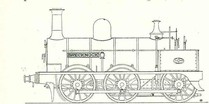
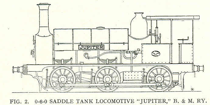
Brecon and Merthyr Tydfil Junction Ry. 55-6.
Lists Locomotive Superintendents: Thomas Simpson who died in an accident
at Maesycwmmer in June 1869; Thomas Mason for the next four years; Charles
Long until 1888; George C. Owen who was found decapitated on 18 April 1909;
James Dunbar until his death on 26 February 1922, and H.F.H. Gibson who acted
as locomotive superintentend until the Railway Grouping. Four locomotives
were available when first section of line opened. Two 0-6-0 tender locomotives
were supplied by Sharp Stewart in 1863 (WN 1408-9) and were named
Alexandra and Brecknock. Two Sharp 0-6-0STs were also supplied
for shunting and banking (WN 1471-2): these were named Jupiter and
Pandora.
 |
 |
Two engines ordered by the "Old" Rumney were also taken into B&M
stock: these were Sharp 0-6-0 tender engines WN 1587-8 and named
Caerleon and Caerphilly.
Road-rail car, L.M. & S. Ry. 57-8. illus.
Built by Karrier Motors Ltd as a Ro-railer with the involvement
of J. Shearman, the road motor engineer of the LMS. The vehicle was capable
of running on either the road or on rails. It was demonstrated on the Harpenden
to Hemel Hempstead and is shown at Redbourn. The bodywork was constructed
by Cravens.
Southern Ry. Literary and Debating Society. 58
Lecture on the locomotives of the Southern Ry. was given by J. Clayton,
on Wednesday evening, 21 January 1931. R.E.L. Maunsell presided. The development
of the later types of locomotives in service on the Southern Ry. was described
and illustrated with photographs and drawings. In opening the discussion,
the chairman referred to the 107 different types of locomotives handed over
at the time of grouping, and spoke of the benefits which had accrued from
standardisation. At the close of the lecture a number of questions were asked
by members of the large audience, and much interesting information regarding
Southern Ry. locomotives was given in the replies.
The Railway Club. 58.
There was a large attendance of members at the January meeting of
the Railway Club, when Lord Monkswell read a paper on Railway reform. While
admitting that great advances had been made in the adoption of safety appliances,
he contended that the railways were suffering from arrested development,
and that, to take the instance of speed alone, the progress made during the
last fifty years was far short of what it should have been, while many of
the reforms had only been adopted after years of agitation on the part of
users. He condemned the wages settlement forced on the railways by the Government
after the War as deplorable, but considered that the railway remained the
most efficient system of transport, and that the solution of the present
position was for the directors to organise the shareholders and strike out
a firm line. At the meeting held on February 6, Mr. W. A. Willox, vice-president,
gave the Presidential address, in the unavoidable absence of Mr. Kenneth
Brown, president. Mr. Willox took as his subject "The Future of British
Railways," and made a number of pertinent and thoughtful suggestions as to
what might be done so that, from the public point of view, the railways might
appear more efficient, more punctual, and more attractive.
Morris, T.E.R. The Forest of Dean tramroads. 59-60. 2 illus.
Southern Ry. Pupils and Premium Apprentices Association. 60.
Sixth annual dinner to be held at the Charing Cross Hotel, London,
on Friday, 6 March 1931. All former pupils and premium apprentices of the
Southern Ry. or its constituent companies are invited to apply to Mr. Eric
L. Forge, 34 North Street, Ashford, Kent, for further particulars.
The sixth annual dinner of the Southern Ry. Eastern Divisional Locomotive
Running Department 60.
Held at Strand Palace Hotel on Wednesday, 28 January 1931. The gathering,
which numbered over 180, was presided over by Mr. D. Sheppy, Eastern Divisional
Locomotive Superintendent, who was supported by Mr. A. D. Jones, O.B.E.,
M.V.O., Mr. G. Oxley, Mr. G. Pullen, and Mr. E. W. Trangmar. After the loyal
toast had been honoured Mr. W. Cole gave "The Chairman and the Eastern Division,"
to which Mr. Sheppy responded. The usual toasts having been given and responded
to the company then proceeded to enjoy, an excellent musical programme provided
by "The Checks" concert party, which, to judge from the generous applause,
was highly appreciated.
[W.A. Stanier lecture]. 60
A comprehensive and interesting lecture was given by Mr. W. A. Stanier,
M.I.Mech.E., Principal Assistant to the Chief Mechanical Engineer, G.W. Ry.,
before the G.W.Ry. (London) Lecture and Debating Society, at Paddington,
on 15 January 1931. Mr. C.E. Lloyd, a director, and also an engineer, occupied
the chair. Mr. Stanier's lecture was illustrated by many lantern slides,
and the various locomotive types introduced by five successive C.M.E.'s were
shown, and their work detailed. Mention was made of the development of the
many types, from the old broad gauge North Star to the present-day e»press
engines, including the "De Glehn" compounds, The Great Bear, "Castles"
and "Kings."
[XA and XB type engines for India]. 60
Order placed with Vulcan Foundry by the India Store Department for
seventeen "XA" type engines, ten of which are for the Great Indian Peninsula
Ry. and seven for the North Western Ry., also ten "XB" type for the East
Indian Ry., and ten "XC" type for the North Western Ry. The Madras and Southern
Mahratta Ry. ordered six "XB" type engines from Vulcan. The Bombay, Baroda,
and Central India Ry. placed an order for four "XD" type engines with the
North British Locomotive Co. Ltd. and four "XC" type with the A.E.G.
Co.
United States Rys. 60.
A.R.A. conducting series of service tests of "connector'! devices
for automatically coupling up the train pipe for the brakes, steam heat,
and air signal pipes, and any eleetrical conduits for lighting, telephoning,
etc.
The disappearance of the locomotive chimney, and the problem
of smoke deflection. 61-3. 4 illus.
Illustrated feature that showed Gresley K3 2-6-0 No. 1000 alongside
Stirling 8ft single No. 1; Boston, Lowell & Nashua Railroad 4-4-0 Eagle
with curved chimney which acted as spark arrester and smoke deflector; Southern
Railway King Arthur type with down draught screens and LNER high pressure
locomotive No. 10000 at speed. Also notes tests conducted by Professor W.E.
Dalby on smoke deflection for No. 10000. See also letter
from P. Weil on page 106.
The first locomotive in South Africa. 63. illus.
Standard gauge 0-4-2 preserved at the Salt River Works of South African
Railways near Cape Town. Manufactured by Hawthorn at Leith (WN 162/1859),
but suggests that either number or date was incorrect.
Great Western Ry. 63.
From 1 January 1931 following unremunerative branch lines in Wales
closed: Vale of Rheidol (Aberystwyth to Devils Bridge) for goods traffic
and for passenger traffic until further notice (1 ft. 11 ½ in. gauge).
Machynlleth to Corris and Aberllefeni for passenger traffic (2 ft. 3 in.
gauge). Cemmaes Road to Dinas Mawddwy for passenger traffic (standard gauge).
On Saturday, 7 February 1931 passenger traffic ceased on Welshpool and Llanfair
narrow gauge line.
Recent special wagons constructed in France. 64-5. 4 illus.
Constructed by De Dietrich of Reichshoffen, Bas-Rhin for Alsace-Lorraine
Railway. Three were bogie vehicles: one a 40 tonne hopper wagon for carrying
coal; two enclosed hopper wagons, one for conveying chalk and another for
potash traffic from Richwiller to to Strasburg, Dunkirk, and Antwerp. There
was also a novel four-wheel tipping wagon.
[Sir Charles Cust]. 65
Sir Charles Cust, who died recently, was a personal friend. of H.M.
The King, and on one occasion acted as driver on the L. & N.W. Ry., and
the "Claughton" locomotive bearing his name was frequently used to draw the
Royal Train.
L. & N.E. RY. 65.
The following "Sentinel" locomotives were recently delivered to the
L. & N.E. Ry.: Nos. 18, 21, 23, 35, 42, 45, 49, 55, 60 to 65, 78, 87,
94, 96, 98. They are all in the Southern area, except 45 (Sentinel 8332),
which is at York. Several of the later ones are on the Great Eastern section,
but No. 55 is at Hitchin and No. 42 at Bidston. In addition to No. 4737,
which was transferred to the Great Eastern section some months ago, further
"N2" tanks have come south from Scotland and are working from Hatfield shed.
Nos. 4730, 2686, and 2689 are there, but have not yet been fitted with condensing
gear. The engine shed at Thirsk has been closed and the four engines stabled
there are now at Northallerton depot.
Mechanically Fired Locomotives: Polish State Rys. 65-7. 2 illus.
diagr.
Mechanical stokers stated to originate in USA circa 1900 with development
of Crawford underfeed system. Duplex D-4 type fitted to Ty-23 series of 2-10-0
(described May 1924) constructed by H. Cegielski.
Setting locomotive valves. 67.
Machine with electric motor which moved locomotive along a track,
rather than using rollers: claimed to be more accurate.
Wastage of locomotive firebox stays and plates. 67-8. 3 diagrs.
The following conclusions were arrived at from the experiments made:
.
I. The wastage of stayheads is primarily due to oxidation of the copper,
but the effect of oxidation alone is generally not serious under dry conditions;
it becomes so under the influence of leakage which causes the detachment,
leading to removal of the otherwise hard and tenacious oxide scale.
2. The composition of the atmosphere of the firebox varies within wide limits;
it is generally oxidising in character, although never containing high
percentages of free oxygen, and is hardly ever, if at all, markedly reducing.
3. The surface temperature of stayheads has not been found to exceed
350°C., and is generally not over 300°C., even in the hottest part
of the box.
4. Leakage from the stays is the result of plastic deformation of the plate
and stay under thermal stresses set up in working.
Notes extracted from paper on "Properties of Locomotive Firebox Stays and
Plates," by Messrs. Hudson, Herbert, Ball and Bucknall, read before the Institute
of Metals at Dusseldorf.
London & North Eastern Ry. 68
No. 2822 Alnwick Castle and 2823 Lambton Castle, of
the "Sandringham" class, have been completed at Darlington Works. No. 4349
is a further G.N. Ry. 4-4-0 working on the Tebay line. No. 2118, a class
T 0-8-0, is stationed at Kirkby Stephen, working ore traffic from Penrith.
As the eight-coupled engines are not allowed over Deepdale and Belah viaducts,
this engine was taken over the Stainmoor summit with empty boiler and tender,
on a goods train.
Whistle reflector, Missouri, Kansas & Texas RR. 69. 2 illus.
Photograph shows locomotive, No. 404, of the M.K.T. RR., provided
with a novel form of whistle or sound reflecting device which has been used
for securing some interesting data concerning the intensity of sound waves
emitted from a locomotive whistle. As will be seen from the photograph, the
whistle is placed horizontally within a parabolic reflector, cast of "lynite"
and located immediately in front of the chimney. The object is to secure
a more direct and intense sound from the whistle when used on approaching
highway level crossings to warn motorists and others of the near approach
of a train. Focussed ahead in this manner there is a corresponding reduction
in sound or noise heard by the engine-men and passengers in the train behind,
as well as those who may be in the neighbourhood on either side of the track.
To measure the effect of the arrangement shown, an "Oscillograph" was used
to record the tests.
[Messrs. Willoughby's model locomotive]. 69
Referring to description of Willoughby's model locomotive in the January
issue (p. 33), it should have been stated that this is a reconstruction and
thorough rebuild of a model said to have been made for the late Sir David
Salamans, who used it for some signalling experiments. About 1885 the model
was on view in Mr. C. Baker's shop in Holborn, and more recently at an amusement
arcade at Blackpool. When the engine was on view at the last "Model Engineer"
exhibition, parts of the original which had been scrapped were also shown:
credit is due to Messrs. Willoughby for rebuilding the engine and all the
good work they have put into it. A misprint occurred in the dimension given
for the length of the steam port; this should be 7/32 in. wide.
Tank Locomotive, North British Ry. 70. illus.
0-4-2WT No. 20, illustrated was first of a class of eight tank engines,
designed by W. Hurst, locomotive superintendent of the N.B. Ry. and built
at St. Margaret's Works, Edinburgh: 1857, Nos. 20 and 22; 1860, Nos. 29 and
49; 1861, No. 96, and in 1862, Nos. 97, 98 and 99. As built, they had coupled
wheels 4 ft. 9 in. dia. and cylinders 12 in. dia. by 18 in. stroke. They
were rebuilt later with 13 in. dia. cylinders, and scrapped in the early
1880s by Wheatley. No. 20 was the third engine built at St. Margaret's, the
previous two being single-driver tanks of similar design. No. 20 at one time
worked the Jedburgh and Kelso service, and the driver in the photograph was
Archie Lightbody, driver on this branch and was over seventy years of age
when he retired. His son succeeded him on the same turn. One of these engines
was involved in a disastrous collision at Penicuik, on the Peebles line,
on October 29, 1863.
Correspondence. 70.
Model "Mail" class locomotive built by Messrs. Willoughby.
G. Geo. Woodcock.
Re Model "Mail" class locomotive built by Willoughby: it seems a pity
that such a fine piece of work should be inaccurate as regards relationship
to prototype in several ways. The "Mail" class as designed by Cudworth in
1861 had no cab, but a plain waisted weather-board; they also were fitted
with Salter safety valves on the dome and were, of course, tender engines,
not tanks.See also letter from G.S. Willoughby on p.
106.
Reviews. 70.
Locomotives of the L.M.S. — past and present. London:
Locomotive Publishing Co. Ltd.
This very interesting and excellently printed book has just been issued,
and in it is given a concise history of each of the railways constituting
the L.M.S. group, though necessarily, on account of space, only brief mention
can be made of the smaller companies absorbed. There are eight colour plates
and seventy-eight illustrations of locomotives, past and present, all of
which are exceptionally well reproduced. A number of marginal pen and ink
sketches of early locomotives enhance the interest, whilst at the head of
each chapter is the "coat of arms" of the company being dealt with. For those
who are interested there is a list of named engines, followed by a table
of leading dimensions of the various L.M. & S. Ry. classes of standard
locomotives, as well as the leading types of the constituent companies, forming
a valuable adjunct to an attractive publication which should find a place
in the library of every railway enthusiast.
Railway carriage and wagon handbook. London: Locomotive Publishing
Co. Ltd. 274 pages, cloth.
Comprehensive book of reference covers a large field of information
on a subject which has hitherto sadly lacked attention. It is a revised and
much enlarged edition of the Railway Carriage and Wagon Builder's Pocket
Book, brought up to date. The book opens with a section on carriage design
and construction, followed by chapters on the varieties of timber in general
use. Then there are sections on the trimming of carriage seats and backs;
painting, with notes on painters' materials, followed by articles on the
use of aluminium for panelling; fabric-covered bodies and enamelled-iron
panels. There is a lengthy section on train lighting, heating, and ventilation,
followed by extracts from the British standard specifications of materials
used in carriage and wagon construction, including axles, tyres, springs,
steel castings, plates, angles, and rivets. Space is devoted to the maintenance
of carriage stock, as well as the examining and progressive repair of coaching
stock in the shops. Chapters dealing with the design and constructional details
of British standard wagons include a section on the mass production of steel
wagons. Wheels, axles, axleboxes, buffing and drawgear, centre couplers,
bearing springs, and metals and alloys for bearings are discussed in turn.
Railway gauges and construction gauges. vacuum and air brakes, and roller
bearings receive attention in the final sections. Nearly fifty pages of quite
useful tables and miscellaneous shop notes are included. The book is well
iliustrated, and is printed on good paper in clear type.
Great Western Ry. 70.
The following new engines have been put into service since the middle
of December: 2-6-2 goods tanks Nos. 5170-5; 4-6-0 passenger Nos. 4981
Abberley Hall, and 4982 Acton Hall, all built at Swindon. 0-6-0
pannier tanks Nos. 6746-9 from the Yorkshire Engine Co.; Nos. 7788-99 from
Sir W. G. Armstrong, Whitworth & Co. Ltd.; Nos. 8725-8 from W. G. Bagnall
Ltd., and Nos. 7754, 7758-61 and 7763 from the North British Locomotive Co.
Ltd.
British Industries Fair, Birmingham, Feb. 16 to Feb. 27. 71. illustration
Hadfield's exhibits including heat resistant steel superheater supports
(illustrated).
Number 463 (14 March 1931)
Directly-driven diesel locomotive, Italian State Rys. 73-5.
illustration, diagram (side elevation)
Extraordinary looking machine constructed by Ansaldo S.A.which
was started from stored compressed air through what looked like steam locomotive
cylinders which provided the rotary movement for the Junkers-Diesel engine
to fire
London, Midland & Scottish Ry. (L. & N.W. Section). 75
Twenty standard 0-8-0s being built at Crewe were for service on the
L. & Y. section. Of these Nos. 9600-10 had been despatched, while Nos.
9611-2 were working trial from the South shed. Ten 2-6-0 mixed traffic engines
were on order at Crewe, as well as a number of Class 2 4-4-0 type with inside
cylinders, similar to Nos. 563-635. Additional tank engines fitted with vacuum
control gear for working motor trains included 0-6-2 type Nos. 7627, 7773,
7796, and 2-4-2 type No. 6676. Prince of Wales class engines Nos. 5628 and
5709 were adapted to work over the Midland division. Two recent transfers
were 4-4-0 compound No. 1106 from Midland to Western division and 0-4-4T
No. 1253 from Western to Midland division. L. & N.W. Ry. 0-6-2T No. 7564
and N.S. Ry. D class 0-6-0T No. 1562 had been withdrawn for scrapping. During
1930 the total L. & N.W. withdrawals was 226, this being made up of the
following types :-2-4-0 (13), 4-4-0 (35). 0-6-0 (58), 4-6-0 (11), 0-8-0 (21),
2-8-0 (3), 0-4-0T (3), 2-4-0T (2), 0-4-2T (2), 2-4-2T (22), 0-6-0T (37).
0-6-2T (19). In addition, there was one departmental 0-4-0T withdrawn, viz.,
No. 3019 (L. & N.W. number).
2-8-0 locomotive, Guaqui-La Paz Ry. 76-7. illustration
Built Avonside Engine Co. for the Peruvian Corporation metre gauge
railway under supervision of Livesey, Son & Henderson, Consulting Engineers.
Oil burning.
Trials of "Mikado" type express locomotive, Belgian National
Rys. 77-8. illustration, diagram
Conducted by F. Legein, Chief Mechanical Engineer, between Brussels
and Arlon and reported in the Bulletin of the International Railway
Congress Associatiion in December 1930
20 H.P. diesel locomotive for Crewe Works. 78. illustration
Hudswell Clarke & Co. 18-inch gauge with McLaren-Benz two-cylinder
engine and simple gearbox. Hall's cranks were used for the coupled wheels
due to the extreme curvature
Bishop's Castle Ry. 78
Local authorities appealed to Ministry of Transport to force Great
Western Railway to take over the railway.
Great Western Ry. 78
9 February passenger service between Abermule and Kerry
withdrawn
President-Elect, Institution of Locomotive Engineers.
79. illustration (portrait)
W.A. Agnew He was Chief Mechanical Engineer (Railways) in 1928; formerly
Mechanical Engineer (Railways) to the Underground Electric Railways of London.
Electrical engineering apprenticeship at King, Brown of Edinburgh whilst
studying at Heriot Watt College. Worked on hydro-electric plant at Foyers
on Loch Ness. In 1901 joined Glasgow Corporation Tramways Department when
system was being electrified. Wrote The electric tramcar handbook for
motormen, inspectors and depot workers (Ottley 2228). In 1904 moved to
London to become Rolling Stock Superintendent of the Metropolitan District
Railway and became Mechanical Engineer in 1907. He was a member of the Institute
of Transport and of the Institution of Mechanical Emgineeers and Institute
of Industrial Psychology
Australian railway notes. J.C.M. Rolland. 79
South Australian Railways 2-8-4 No. 720 from the Islington Workshop
with booster on trailing truck was described as "light"!. Had 22 x 28in
cylinders, 4ft 9in coupled wheels. 59.5ft2, grate area,
2975ft2 total evaporative heating surface and 751ft2
superheat, thermic syphons, cast steel frame and 12-wheel tender. The Victorian
Railways N class 4-8-2: Nos. 130-9 were in service and thirty were
planned to be built from the Newport shops. These were intended for lighter
lines. The Sydney Limited ran the 129¼ miles from Albany to melbourne
non-stop in three hours over a mainly single track line. The New South Wales
Government Railways had 25 Clyde Engine Works 4-8-2 designed to cope with
1 in 33 gradients into the Blue Mountains. Five had been allocated to the
Goulburn shed to work the heavy seasonal wheat traafic. They were turned
on triangles
Drewry saloon rail inspection car at the Buenos Aires Exhibition.
80-1. 3 illustrations
British Empire Trade Exhibition: with its basket chairs interior looked
more like a mobile home
The wheels have Lang wood centres with forged steel tyres and cast-steel hubs. These wheels are very strong, are not affected by varying climatic condi- tions, and run much quieter than all-steel wheels. The axleboxes are provided with roller bearings, shoe brakes act on all four wheels, operated by hand lever and foot pedal. The controls are very conveniently arranged at the left-hand side at each end of the car.
Great Western Ry. 81
New 4-6-0 engines of the Hall class: Nos. 4983 Albert Hall,
4984 Albriqhton Hall, 4985 Allersley Hall, 4986 Aston
Hall, 4987 Brockley Hall, 4988 Bulwel! Hall, 4989 Cherwell
Hall, 4990 Clifton Hall, and 4991 Cobham Hall. Other engines
completed at Swindon are 2-6-2 mixed traffic tanks Nos. 5176-8. W.G. BagnaIl
Ltd. delivered 0-6-0 pannier tanks 8729-30 and the North British Locomotive
Co. Nos. 7762 and 7764-9.
Standard locomotives of the German Railways. 81-3.
.illustration, diagram
Two and three-cylinder 2-10-0 freight locomotives
In January issue there is an article by Alfons Meckel explaining the main
theoretical and practical principles underlying the new German scheme of
locomotive standardisation and we propose in this and subsequent articles
to illustrate the several locomotive types of which par- ticulars appeared
in the table on page 8. This table is useful in that it demonstrates the
dimensions common to the various classes· and it will be noted that
a relatively large number of major details have been found applicable to
many series. In fittings and accessories also this policy of stan- dardisation
has been very ably executed and can hardly fail to be productive of valuable
economies; indeed, we understand that the new system has already proved most
satisfactory, despite the fact that there is still, and must necessarily
be for some years, a great quantity of locomotive stock of widely diverse
character. The ' full benefit of standardisation can only be fully realised
when these pre-standard engines have disappeared. The express passenger
locomotives, all of the "Pacific" formation, were dealt with in the above-
mentioned article, and we now illustrate the two types of heavy freight
locomotives known respec- tively as Series 43 and 44. These are at present
the most powerful machines standardised on the German railways; though we
believe the possibility of 12- coupled engines has been considered should
yet more powerful units be demanded. As seen in the table, all dimensions
are identical, with the important exception of the cylinders and a consequent
discrepancy in the rated tractive effort and some minor differences in weight.
These varia- tions are due to the fact that the engines of Series 43 are
provided with two cylinders and those of Series 44 with three cylinders.
The former is that depicted by the line drawing Fig. 1 and the latter by
Fig. 2, and their respective cylinder measurements are 720 mm. by 660 mm.
(28.34 in. by 25.98 in.) and 600 mm. by 660 mm. (23.62 in. by 25.98 in.)
dia- meter and piston stroke. The cylinder volume is 268.5 dm." for the
two-cylinder engine and 186.5 dm." for the three-cylinder locomotive; the
respective tractive efforts, on the official reckoning of 50 per cent. of
the boiler pressure as m.e.p., are 17,100 kg. (37,698 lb.) and 17,800 kg.
(39,241 lb.).* The weight of the three-cylinder engine is also a little greater,
being 103.7; 114.1; and 99.4 metric tons for empty, full, and adhesion weights,
as compared with the corresponding figures of 100.9; 111.3; and 96.6 m.t.
for the two-cylinder locomotive. The leading dimen- sions are to be found
in the table, but we here repeat * Calculated on the more optimistic value
of 85 per cent. B.P. usual in this country, the tractive efforts would be
approximately 29,000 kg. (63,900 lb.) and 30,200 kg. (66,560 lb.).
Phillipson, E.A. Steam locomotive design: data and formulae. Chapter
VI. Boiler mountings: steam using auxiliaries. 83-6. table
Clack valves, ejectors and oil fuel
Six-coupled tank locomotive for Persia. 88-9. illustration, diagram
Peckett & Sons supplied two 2ft 6in gauge 0-6-2T engines to the
Anglo-Persian Oil Co. at Abadan. The diagram shows the oil burning
system
Condensing tank locomotive, L.M. & S. Ry.. 89. illustration.
Condensing apparatus was fitted to locomotives engaged on the St.
Pancras suburban services for working to Moorgate: No. 15524
illustrated.
Brecon & Merthyr Tydfil Junction Railway. 90-1. 3 illustrations
Notes on the "Chronicles of Boulton's Siding. 92-3.
3 figures
Fig. 1: drawing (side elevation): 2-4-0T Rigg (partly
dismantled)
Fig. 2: photograph long boiler freight locomotive Lord
Robartes at Stratford Works in 1873
Fig. 3: Boulton's own works plare
T.E.R. Morris. The Forest of Dean tramroads. 96-7.
Beyer-Garrett locomotives, Nigerian Rys. 98-9. illustration, diagram (side elevation)
J.N. Maskelyne. Some further notes on the Stroudley
"Singles," L.B.&S.C. Ry. 99-103. 3 diagrams (side elevations)
See also letterr from Ernest F. Smith
J.G.R. Sams. Modification of British goods equipment. 103-5
Metropolitan-Vickers Electrical Co. Ltd., Long Service Association.
105
The staff canteen at the Trafford Park Works was the scene of the
annual meeting of the association on Monday, February 23. Sir Philip A M.
Nash, president of the association, was unfortunately unable to take the
chair owing to illness, and his place was taken by G.E. Bailey. Sir Felix
Pole, chairman, and Lusk, vice-chairman of the A.E.I. Ltd., as well as several
directors and officials of the British Thomson-Houston Co., were present,
also Mr. Philip Lang, former managing director of the British Westinghouse
Co.
Obituary. 105
It is with great regret that news reaches us of the death of Herbert
Thomas Walker at his home at South Orange, New Jersey, on January 26. Born
in London seventy-four years ago, Walker was for a time in the office of
Lloyd Wise & Co., patent agents, of Lincoln's Inn Fields. He went to
the United States in the early 'eighties and was connected with the
Scientific American as a draughtsman for forty years. His hobby was
compiling the history of railways and their locomotives, both British and
American. From time to time LM published articles written and illustrated
by Mr. Walker, notably those on the Bodmer locomotives, the last of which
appeared in our February issue. A collection of 200 of his drawings will
be found in the Rosenwald Industrial Museum, to be opened in connection with
the Chicago Exposition of 1933.
Death on 28 February 1931 at Acton, of John Armtrong,
M.V.O. 105
Former district locomotive superintendent of the Great Western Ry,
at Paddington. He was seventy-nine years of age and retired in 1916, after
over fifty years' service. Armstrong was in charge of the Royal trains in
three reigns, and superintended the funeral trains of Queen Victoria and
King Edward.
Newcomen Society. 105.
On Wednesday, 18 March, at Caxton Hal1, Westminster, at 5-30 p.m.,
a paper entitled "John Nuttall's Sketch Book and Notes on Wrought Iron Details
for Early Locomotives" wil1 be presented by J. G. H. Warren, M.I.Mech.E.
The centenary of the death of William Syrnington occurs on 22 March, and
the council proposes on that day to deposit a chaplet on his memorial at
St. Botolph's, Aldgate.
Buenos Aires Great Southern Ry. 4-2-2 Engines No. 101 to
105. 105
Very few "singles" were then at work, it will perhaps be of interest
again to refer to the engines illustrated on page
386 of Vol. 36. The principal dimensions as quoted on the official diagram
are appended ;- These engines are known as Class 5, and were numbered 191
to 195 when first built; when the whole of the locomotive stock was renumbered
in 1912, the numbers were al tered to 101 to 105.
Correspondence. 105
Old Stockton and Darlington Ry. locomotives.
Mecanicien
Re Beckerlegge's letter in the January issue regarding old Stockton
and Darlington Ry. locomotives. Nos. 81 and 82 were purchased from
the Edinburgh & Glasgow Ry. in 1854, the former engine withdrawn from
traffic in 1867 and the latter in 1882. The Seaton Delaval Col1iery No. 4
was purchased from the North British Ry. about 1864, and was of a much lighter
construction than No. 81 Millar and 82 Hawthorn, and when delivered
at the col1iery it bore the original number plate of the N.B. Ry. on the
boiler, the Colliery people cut off part of the plate bearing the word "North"
and left the number and name thus; "4 British." The engine was sent to Messrs.
Stephensons in 1867 for rebuilding, and I would emphatically state that it
was an entirelv different engine from the Stockton & Darlington No. 81
Millar. No. 159 York, afterwards No. 1159, and in July 1904
altered to No. 1674, built by Gilkes & Co. (No. 125), February 1862,
rebuilt in 1878, and cut up at Darlington in 1905 with over 1,000,000 miles
to her credit; this cannot very well be the Clio owned by the Seaham
Harbour Dock Co. The Clio was originally No. 125 North Eastern Ry.
and one of E. Fletcher's No. 120 class coal engines erected at Hartlepool
in March 1875 under the supervision of the Thomas James. The boiler, cylinders,
and wheels were obtained from Gateshead Works. No. 125 was sold to the Seaham
Harbour Dock Co. in April 1911, and a few years ago she was reboilered with
a second-hand boiler obtained from the railway company, and at the same time
received the rather more commodious cab belonging to the locomotive
Ajax, which was originally a Blyth & Tyne locomotive and ran on
the N.E. Ry, as No. 1308 and latterly No. 1719. The name plate Ajax
has now been removed and the Clio has her original name plate. The
varying numbers on the boiler mountings are accounted for by the fact of
the engine No. 125 receiving transfer boiler during the last overhauls previous
to being sold out of service.
Counter-balancing of British locomotives. F.W.
Brewer
Re letter which appeared in January issue, p. 35,
Ernest F. Smith stated that Stroudley used balanced
crank-axles, although the fact that he had done so had never been mentioned
in print. For my own part, the point in question is certainly new to me;
moreover, no reference to the matter occurs in
Stroudley's well-known (Inst. CE.'s)
paper on the locomotives of the L.B. and S.C Ry., in which Stroudley
went fully into the method employed by him for counter-balancing the revolving
and reciprocating masses of his Brighton-built engines.
Of those engines, the 0-4-2 "Gladstones" would I think be more likely to
have had balanced inside cranks' than the other classes (if at all), yet
the sectional drawings of these express engines do not show that they were
fitted with such cranks.
Which, then, of Stroudley's locomotives had the 9-in. rear extensions to
the crank hoops about which Smith wrote? Were they any of his few engines
on the Highland line, or were they some of his L.B. and S.C Ry. engines?
Perhaps he will be kind enough to send full particulars. For it is
decidedly strange that all mention of so notable and unusual feature (which
it would have been in those days) should have been omitted by Stroudley from
a paper in which he described his locomotive practice in detail, including
the customary rules for balancing the motion parts by means of weights in
the rims of the wheels, ·and not otherwise.
Locomotive chimneys and smoke deflection. P.
Weil
One of the chief reasons why the steam persisted in "hugging" the
boiler top of such engines as the King Arthurs of the Southern Ry, was, I
understand, owing to their comparatively low exhaust pressure when running
at speed with early cut-off. In fact, they were too efficient for comfort,
as far as clear look-out was concerned. When accelerating, or mounting a
bank. with consequent higher exhaust pressure, there was no such trouble.
The same remarks apply to compound engines with their low exhaust pressure,
and it would be interesting, therefore, to know whether the picture of L.
& N.E. Ry. No. 10,000 appearing on page 62 was taken at a part of the
line which is level or on an up-grade.
I believe that a high-pressure steam "screen" issuing vertically from the
back half periphery of the funnel was tried on the "King Arthurs" before
the adoption of the German sheet steel "side screens," but that it was found
that this expedient actually made things worse! There was another method
employed in Germany before WW1 on the Atlantic four-cylinder compounds of
the Prussian lines, which consisted in placing an upwardly sloping steel
"apron" from the front of the funnel to the back, i.e., starting at the front
base of the funnel, and ending at the back rim. This, I believe, was fairly
successful, but, of course, required a reasonably high funnel. Regarding
the "machines à bec" of the P.L.M., these were, of course, introduced
with a view to reducing head wind resistance, and although certain designs
of "becs" did probably also act as smoke deflectors, they were not primarily
designed for that purpose.
In conclusion, he paid tribute to the designer of the Southern Ry. "King
Arthurs" and "Lord Nelsons" in having evolved a form of "side sheets" which
in no way detract from the fine appearance of these magnificent machines.
"Side sheets" are a necessary evil which, if applied without due artistic
thought, might very easily be a source of great disfigurement.
Model S.E. Ry. Locomotive. G.S. Willoughby
Re. G. Geo. Woodcock's letter in February Issue re our model S.E.
Ry. locomotive, firstly, let me state quite definitely that it is not a model
of one of Cudworth's "Mail" engines. These engines had driving wheels of
7 ft. dia.; 4 ft. 6 in. leading wheels, and 3 ft. 9 in. trailing wheels,
also a long firebox with longitudinal midfeather. Our model is of a much
smaller engine, and has a scale of 6 ft. dia. drivers and 4 ft. leading and
trailing wheels, also an ordinary deep firebox between the driving and trailing
axles. The outside main frames are also a different shape, at the front and
rear axleboxes, from those of Cudworth. In fact, it has few of the
characteristics of Cudworth's singles, but practically all of J.C. Craven's,
of the L.B. & S.C Ry.
As stated in the February issue, this model originally belonged to
Sir David Salarnans prior
to 1885, and as this gentleman was a director of the S.E. Ry. it seems to
be hardly likely that he would have such a large model built without some
definite prototype. We went to a great deal of trouble during the reconstruction
of this engine to discover a possible origin, and the conclusion we came
to was this : It is well known that Cudworth and Craven were very friendly
and used to copy each other in some of their engines. and also to loan them
occasionally; is it not therefore likely that an engine such ,,~ the model
represents started its life on the L.B. & S.C Ry. as a tender engine,
and was in its later days either lent or sold to the S.E. Ry. and altered
by them in small details such as cab. bunker. and well tank, and perhaps
chimney top. and then used either on a branch line or for a directors' saloon
engine? There have been many such transactions in locomotive history of which
no record has been preserved. . The link motion details and many others,
such as axle-boxes, frames, safety valve casing, buffers, etc., etc., are
absolutely "Craven." I may add that the number plates on the sides of the
cab are the original ones and bear the inscription: "No. 1, South Eastern
Railway." The cab anrl bunker are also original, but have been reconditioned.
I may state that I have never before seen such an appalling collection of
scrap as this engine was when we came to pull it to pieces; nothing was properly
fitted or in line; not a single original nut, bolt, stud, or pin remains,
and all other parts have been either reconstructed or renewed. [KPJ: Sir
David "Salamans" has been assumed to be one or other of Sir David Salomons
in which case it is surprising that the comments on workmanship were
not refuted: the more probable Sir David had died in 1925]
Of all railways, the history of the S.E. Ry. seems to be the most obscure
from the locomotive standpoint, but would make most interesting reading if
it could be compiled. In conclusion, if Mr. Woodcock would like a photograph
of the model, I would be very pleased to give him one through your office.
Mechanical stokers in Europe. D.R. Carling.
107
Ini Februiary LM it is stated that Poland is thought to be the first
country in Europe to use a mechanical stoker, but I believe that a stoker,
of the same type as that mentioned, was fitted to one of the "Pacific" type
engines, class 10bis of the Belgian National Ry., as long as five years ago.
This was done following a decision to that effect made at the International
Railway Congress meeting in London in 1925.
This information is from an article on "Mechanical Stokers for Locomotives"
in the paper Baldwin Locomotives for January 1928.
I do not know the result of this experiment or if the stoker is still in
use. The new Belgian locomotives seem to be hand-fired.
The origin of the balanced locomotive. F.W. Brewer
At the end of his interesting article in your February number, on
Bodmer's 2-4-0 goods tank engines, Mr. Herbert T. Walker stated .that a
description would be found in Sekon's
Evolution of the Steam Locomotive. From this, it might be thought
that these 2-4-OTs were among those dealt with by Sekon. Such was not the
case, however.
The first Bodmer engines to which Sekon referred were four with 4 ft. 6 in.
six-coupled wheels, and 18 in. by 24 in. cylinders. These engines, the names
of the makers of which were not given, were supplied to the Manchester and
Sheffield Ry. in 1845. They were stated to have been "powerful goods locomotives"
(an expression similar to that quoted in Mr. Walker's article), weighing
24 tons, and capable of hauling a gross load of over 1,000 tons. Such an
achievement would, however, be a very improbable one on the part of a 24-ton
engine.
Sekon next cited an odd Bodmer locomotive on the Manchester and Sheffield
line. This was said to have been constructed (seemingly in 1844) by Sharp
Bros. & Co. It had 14 in. by 20 in. cylinders, and 5 ft. driving wheels;
type, whether single or coupled, was not recorded. Next came the S.E. and
L.B. and S.C. Bodmer "single-wheel" engines, and after these Sekon mentioned
another odd example, in regard to which, for the first time, the position
of the cylinders (in case outside the frames) was given, similar information
in the case of the other "Bodrners" having been ignored. It is well known
that the South Eastern & Brighton Ry, engines had inside cylinders, and
the inference is, in the absence of any statement to the contrary. that the
"Sekon" M. & S. Ry, engines also had inside cylinders.
The solitary outside cylinder "Bodmer," quoted by Sekon, had 22 in. by 24
in. cylinders, 7-ft. driving wheels, and 110-lb. steam pressure. Nothing
was said as to the type of the engine, the builder, or the railway on which
it worked, or the date when the engine was put into service. All of the foregoing
locomotives had Bodmer's patent double pistons the stated stroke being equally
divided in each cylinder the two pistons moving in opposite directions. The
M. & S. Ry. 2-4-0Ts dealt with by Mr. Walker had 6 ft. 2 in. coupled
wheels and 17 in. by 30 in. outside cylinders; hence, they did not correspond
with any of the Bodrner engines as chronicled by Sekon in his work, but were
additional examples of Bodmer's designs. Assumedly, all of Sekon's examples
were tender engines.
North British Ry. tank engines. C. Hamilton Ellis.
With reference to the. very interesting account of Mr. W. Hurst's
tank engines for the North British Ry. in the February issue, the article
runs: "They were rebuilt later . . . . and were scrapped in the early 'eighties
by Mr. Wheatley." This should read "Mr. Drumrnond," as the latter succeeded
the former in 1875. Outclassed by Wheatley's 0-6-0 saddle-tank engines of
the early 'seventies, they were finally taken out of service on the introduction
of the relatively modern "Drumrnond" tank engines previous to 1881, by which
time all four of the standard "Drummond" tank engine types had appeared.
The late E.L. Ahrons, by the way, gives the numbers of these engines as 96-99
and 103-108. The new Nos. 96 and 97 were "Drumrnond" "Terrier" tank engines
Arbroath and Bonninqton ; 98 and 99 were the small 4-4-0T engines
Aberfoyle and Roxburgh; 103-5, Montrose, Roslin,
and Penicuik; while 106~8 were three more "Terriers," Tayport,
Leuchars, and St. Andrews.
Reviews. 107
Les Chemins de Fer Coloniaux de l'Afrique, Lionel Wiener, Paris:
Librairie Dunod, 574 pages. 30 maps. Paper covers.
Conditions influencing the establishment and operation of railways
in the Colonies embody many varying factors; the political and administrative
conditions, physical features of the districts served, general difficulties
encountered, such as labour, construction of works, etc., are seldom similar.
A study of the railway systems in the African Colonies is bound to be of
interest, and the author's work will be appreciated by railway experts and
all who study questions of Colonial expansion. The book, which is in the
French language, deals with the railways in the British, French, Belgian,
and Portuguese Colonies in Africa, and gives the general characteristics
of the various systems and reasons for their construction. Mention is made
of the types of locomotives used. Quite a number of maps show the existing
lines and extensions proposed, and tables of statis- tics of the lines open
for traffic, with, in some cases, traffic returns, add to its value for reference
purposes. Covering such an immense field, the facts and data have had to
be arranged as concisely as possible, and a certain amount of condensing
of the information has been inevitable, but the author is to be complimented
on the general arrangement of the work.
Materials and structures, Vo!. I, E. H. Salmon, London: Longmans,
Green and Co. 396 illustrations, 638 pages.
The present volume deals only with the elasticity and strength of
materials, and is designed primarily to assist students taking the B.Sc.
(Engineering) degree at London, or the examination for the Associate Membership
of the Inst. of C.E., and other similar examinations, but it is also intended
as an introduction to the mass of information now available to the engineer.
It is divided into two parts. Part 1 deals with elastic strains and stresses
and Part 2 with the properties of materials as determined by experiment.
Number 464 (15 April 1931)
Great Western Ry., 2-6-2 side-tank locomotive.
109 + Supplement (sectional elevation and plan: missing from copy
inspected)
51XX class
Three-cylinder passenger engines, Southern Ry. 109-10. illustration.
2 diagrams. (side. & f/ront elevations.)
U1 class: No. A891 illustrated: first of twenty completed at Eastleigh
Works.
Great Western Ry., 0-6-0 pannier tank engine. 110.
illustration
57XX: 67XX series No. 6743 illustrated built Yorkshire Engine Co.
Ltd. WN 2249-73 and GWR RN 6725-49.
New locomotives, Romney, Hythe & Dymchurch Ry. 111-12. 2
illustrations
15 inch gauge American outline 4-6-2 Pacifics built Yorkshire Engine
Co. Ltd.: No. 9 Doctor Syn (illustrated) and No. 10 Black Prince;
Captain J.E.P. Howey is shown at the controls (presumably outside builder's
works).,
Petrol rail motor, County Donegal Rys. 112. 2 illustrations
3ft gauge railcar initiated by Henry Forbes, general manager, with
the assistance of G.T. Glover, engineer to the line. Built at Dundalk Works
and fitted with Reo six-cylinder petrol engine. Could seat 32 passengers
in bus type seating and haul a trailer. Illustrations show both exterior
and interior.
G.W. Ry. engine "City of Truro" sent to York Railway
Museum. 112.
No. 3717 City of Truro, formerly No. 3440, which achieved a
speed in excess of 100 mile/h on 9 May 1904 had been renovated at Swindon
Works and left there for York at 03.30 on Friday 20 March, reaching Banbury
at about 07.00, from whence it was taken to York as part of an ordinary goods
train.
Institution of Locomotive Engineers: Paper on "Improvements
in water pick-up gear", by Mr H. Chambers. 113.
Paper No. 277.
After narrating the early adoption of such to enable locomotives to
undertake long runs by Mr. John Ramsbottorn, the locomotive engineer of the
L. & N.W. Ry., Chambers proceeded to describe in detail the most approved
arrangements used on the LMS Ry., devoting particular attention to the many
improvements which had been incorporated in the latest forms used on that
line.
A verv interesting account was given of the results obtained in experiments
made with a special tender constructed at Derby Shops, in which an observation
chamber was provided. Careful notes made in actual working had enabled great
improvements to be made in the provision of anti-splash devices to enable
the maximum amount of water to be taken whilst an engine is passing over
the trough with a minimum amount of waste.
Provision of a deflector plate about 1 ft. 4 in. in front of the scoop has
enabled the following records to be made: (1) Average increase of water picked
up at all speeds was about 200 gallons, representing about 17% improvement;
(2) The amount of water picked up is constant for all speeds between the
minimum or critical speed and 60 m.p.h., but as speed increases the amount
of water splash causing waste rapidly increases; (3) The reduction of water
lost by splash is constant for all speeds and was about 400 gallons, representing
a reduction of about 50% at a speed of 40 m.p.h. The water splash as a percentage
of the total water taken from trough, for the two cases is as follows
| Min. speed 20 m.p.h | 60 m.p.h. | |
| Without deflector | 20% |
50% |
| With deflector | 8% |
30% |
The author proceeded to show the huge amount saved by the total number of engines equipped with this pick-up gear on the L.M. & S. Ry., some 4,000 locomotives, assuming each locomotive fitted made an average of two pick-ups per day, not an excessive figure considering that on some through runs there were as many as nine pick-ups per turn. Daily there was a saving of pumping 7,000,000 gallons of water.
Valve gear of L. & N.E. Ry. high-pressure locomotive.
113-15. 2 diagrams.
See also page 38 et seq. for
abstract of the paper read by H.N. Gresley before Institution of Mechanical
Engineers.The special valve gear employed on high-pressure locomotive No.
10000: drawings of extremely ingenious motion, which not only constitutes
a most interesting detail of a highly original engine, but also appears to
offer the simplest method hitherto devised to allow of independent cut-off
control in compound locomotives. Since the railway locomotive has to furnish
a power output that varies almost momentarily, the problem of designing a
two-stage expansion system suited to it is far more difficult than with marine
or stationary engines, in which the load in n:ost cases remains fairly constant
over lengthy penods. In order that the power developed in the high and low
pressure elements shall be reasonably well balanced the degree of expansion
in the low-pressure cylinder must be a fraction of that prevailing in the
high-pressure cylinder, and in practice this is best brought about by an
alteration of relative cut-off of the high-pressure and low-pressure valves.
B. Reed. Electric locomotive equipment. 116-18. diagram (elevation & plan).
L.M. & S. Ry. "Ro-railer". 118-19. 2 illustrations.
Beyer-Peacock self-trimming coal bunker. 119-21. 3
illustrations.
Rotary coal bunker fitted to LMS 2-6-6-2 No. 4986
Phillipson, E.A. Steam Locomotive Design: Data and Formulae. Chapter
6. Boiler mountings: steam using auxiliaries. 122-25. diagr., 6 tables.
Right-hand versus left-hand drive: former tends to obstruct fireman's
work. Vacuum ejectors, air brake pumps (use one third less steam than an
ejector), injectors, savings of exhaust steam ejectors. feed pumps, train
heating (including steam consumption). tube cleaners, boosters, turbo-generators
for electric light, and mechanical stokers.
Experimental locomotive testing plant. 125.
Brecon & Merthyr Tydfil Junction Railway. 126-7.
5 illustrations
Continued from page 91. Four tender engines, previously in use on
the Cambrian Rys., were also allotted to the B. & M. Ry. Of these, two
were of the 0-6-0 type, one, which had been No. 20 Vulcan on the Cambrian
Rys., but was renumbered 3 on the B. & M. Ry., having been built by Sharp,
Stewart & Co. in 1862 (WN. 1342), and was precisely similar to the
Caerleon and Caerphilly. The other, No. 16 De Winton on
the Cambrian Rys. and renumbered 6 by the B. & M. Ry., was built by Manning,
Wardle & Co. in 1862 (WN. 41), (Fig. 6), and, though of a generally similar
type, differed both in dimensions and other characteristics which followed
the practice of the builders. The wheels were 4 ft. 6 in. dia. on a wheelbase
of 14 ft. 3 in., and the cylinders were 16 in. by 22 in. The tender was on
six wheels of 3 ft. 6 in. dia. with a wheelbase of 10 ft. 6 in., and had
a tank capacity of 1,350 gallons. This engine was named after Mr. J. Parry
de Winton, the chairman until 1865 of the B. & M. Ry. and a local
banker.
The other two were of the 0-4-2 type, and on the Cambrian Rys. had been No.
4, Wynnstay (Fig. 7), and No. 6, Glansevern. They were built
by Sharp, Stewart & Co. in 1859 (WN 1146 and 1148), and were renumbered
by the B. & M. Ry. 12 and 11 respectively.
The coupled wheels were 5 ft. and the trailing 3 ft. diameter, the wheelbase
being 7 ft. 2 in. from leading to driving, and 6 ft. 8½ in. from driving
to trailing. The cylinders were 15½ in. by 22 in. The boiler, with an
inside diameter of 3 ft. 8 in., had 145 tubes 2 in. by 10 ft.2 in., which
contributed 800 sq. ft. of heating surface to a total of 873 sq. ft., the
grate area being 13 sq. ft. The tender was on four 3 ft. 6 in. wheels and
carried 1,200 gallons of water and 3 tons of coal.
Three small saddle tanks of Manning, Wardle & Co.'s build, and all precisely
alike, complete the list of engines acquired from Messrs. Savin and Ward.
The origin of these is a little obscure, but one or more of them had previously
been in the service of the Cambrian Rys. The engine, which on the latter
line had been No. 15 Hereford, and was built in 1862 (WN 49), was,
on transfer to the B. & M., renumbered and renamed 16, Lady Cornelia
(Fig. 8). Another, named Usk, also built in 1862 (WN 58), is thought
to have been No. 22 on the Cambrian Rys., but was renumbered 15 by the B.
& M. Ry. The original service in which the third was engaged cannot be
traced, nor its date of construction, but it is understood to have been employed
in making the Cefn branch, and was numbered 17 and named Blanche by
the B. & M. Ry. These engines had 3 ft: 1 in. wheels, and inside cylinders12
in. by 17 in., the wheelbase being: leading to driving 5 ft. 5 in., driving
to trailing 5 ft. 4 in. The boiler, 2 ft. 9 in. by 7 ft. 9 in., contained
seventy-eight 2-in. tubes. The heating surface was: tubes 330 sq. ft., firebox
40 sq. ft., total 370 sq. ft.; grate area 6.75 sq. ft. The saddle tank carried
450 gallons of water, and the engine weighed 16 tons 11 cwt. in working order,
5½ tons being on each of the leading and trailing axles, and 5 tons
11 cwt. on the driving. The Usk, commonly called the Little Usk
to distinguish it from the tender engine, No. 9, was sold to Mr. J. Mackay,
of Newport, and the Lady Cornelia to the Tuthill Limestone Co. The
latter engine was named after Lady Cornelia Henrietta Maria Churchill, eldest
daughter of the seventh Duke of Marlborough, who, in May 1868, was married
to Sir Ivor Guest, the famous ironmaster of Dowlais and afterwards Lord Wimborne.
The twenty-three engines described above formed the stock of the line at
the completion of the system in 1868. Six further engines, to meet the
development of the traffic, were added by the end of 1872. Although these
were, in the main, similar to the Atlas class, in order to increase the adhesive
weight and extend their working range, they were provided with larger tanks,
and the driving axle was placed 5-in further back, the distance between driving
and trailing centres bemg only 4. ft. 9 in. Like their predecessors, they
were designed and built by Sharp, Stewart & Co. and delivered in three
lots two at a time. No. 24 Cyfarthfa and No. 25 Sir Ivor (WN
2059 and 2087) were built in 1870, No. 26 Samson and No. 27
Hercules (WN 2144 and 2166) in 1871, and No. 28, Rumney (Fig.
9), and No. 29, Taff (WN 2261 and 2260) in 1872. In this class
the tanks carried 900 gallons of water, and the bunkers 20 cwt. of coal,
the loaded weight being 36 tons 19 cwt., distributed to give 11 tons 1 cwt.
on the leading, 12 tons on the driving, and 13 tons 8 cwt. on the trailing.
Nos. 28 and 29 were fitted with the Chatelier
counter-pressure brake when new. The Cyfarthfa and Sir Ivor
were sold to the Cyfarthfa Ironworks, Sir Ivor becoming Cyfarthfa
No. 12, and the Samson to the Rhymney Ironworks. The Hercules
was involved, as previously stated, in the Talybont accident of December
2, 1878. The Taff was sold to the Consett Iron Co. and became their
No. A9. It was rebuilt by A. Barclay & Co. in 1904 and finally sold for
scrap in 1924.
In 1877 the B. & M. Ry. purchased from the Neath and Brecon Ry. two engines
which that company had to dispose of in consequence of an arrangement it
had come to with the Midland Ry. for working a portion of its line. They
had been Nos. 7 and 8 on the Neath & Brecon Ry., and were built by the
Avonside Engine Co. in 1874 WN. 1013-4), and on the B. & M. Ry. were
numbered and named 30 Alt and 31 Tor respectively (Fig. 10).
They were saddle tanks of the 0-6-0 type, but differed from the standard
engines of the B. & M. Ry. in having outside frames. The wheels were
4 ft. 6 in. diameter on a base of 15 ft. 8 in., and the cylinders were 17
in. by 24 in. The tanks had a water capacity of 990 gallons, and the
bunkers held 2 tons of coal. These two engines were only withdrawn from service
in 1921, and broken up at Machen the following year, before the line was
taken over by the G.W. Ry.
There was no further increase in the number of locomotives during the next
thirty years, but, with the exception of the two just referred to, the whole
of the engines previously described were disposed of before the end of 1905,
and consideration must now be given to the newer series of locomotives which
replaced them and which carried on the service until the amalgamation. (To
be continued) . Illustrations (all from photographs except Fig. 8 –
drawing: Fig. 6 0-6-0 goods engine, De Winton, No. 6, Brecon &
Merthyr Ry.; Fig. 7. 0-4-2 tender engine, No. 12, Wynnstay, B. &
M. Ry.; Fig. 8. 0-6-0 saddle tank engine, No. 16, Lady Cornelia, B.
& M. Ry.; Fig. 9. 0-6-0 saddle tank loco., No. 28, Rumney Brecon
& Merthyr Ry.; Fig. 10. 0-6-0 saddle tank locomotive, No. 31, formerly
named Tor, Brecon & Merthyr Ry.
Accident at Leighton Buzzard, L. M. and S. Ry. 127.
On Sunday, March 22, the 11.30 a.m. express from Euston to Glasgow
and Edinburgh was derailed at Leighton Buzzard as it was crossing from the
down fast to the down slow line, fifty minutes later. Three passengers and
the driver, fireman, and one of the restaurant car staff lost their lives.
The engine was No. 6114, Coldstream Guardsman, of the "Royal Scot"
class. The train consisted of fourteen coaches the first four of which were
destroyed. Colonel Mount, chief inspecting officer of railways, has been
appointed to enquire into the cause of the accident. The inquest was opened
on Tuesday, March 24, and after evidence of identification, was adjourned
until April 16.
The passenger service on the Bankfoot Light Ry. (Strathord Junction to Bankfoot), L.M. & S. Ry., was WIthdrawn on April 11 but the branch will still be used for goods and stock traffic.
T.E.R. Morris. The Forest of Dean tramroads. 128-30. 3 illustrations
The Viceroy of India and the railways there. 131-2.
Railway and Canal Transport Costs ..
Locomotive Stock Returns, December 31, 1930
R.K.E. Woodhouse. Some early Locomotives of the New South Wales Government Rys. 134-6. 4 illustrations
H.C. Casserley. The Castlederg and Victoria Bridge
Tramway. 137-9.
Normally known as a railway. Most of the photographs were taken
by the Author: exception being petrol railcar which had been withdrawn by
time of visit. General Manager was W.J. Davidson and engineer was G.H.
Pollard.
New all-steel third-class cars, Netherlands Rys. 140-2. 3 iillustrations, diagram, plan
Personal. 142
G.A. Musgrave, works manager, Cowlairs, LNER appointed locomotive
running supertintendent Scottish Area succeeding I.S.W. Groom who moved to
similar position in Southern Area.
T.H. Sanders. 142
Made a Freeman of the University Spring Trades Society of Sheffield
for his work on springs.
R.B. McColl. 142
Appointment as President and Director of McIntosh and Seymour Corporation
of Auburn, NY: once native of Kilmarnock and apprenticed on
G&SWR.
William Tolley retirement. 143
After forty-eight years' service on the old Midland and L.M. &
S. Rys., Mr. William Tolley, of Derby, retired at the end of March. Mr. Tolley
was known throughout the Midland Division for his activities in connection
with the Locornotive Mutual Improvement classes as instructor. During his
railway service Mr. Tolley has graduated from engine cleaner, fireman, and
driver, to the rank of locornotive inspector, which he attained in 1904.
As a result of the lead set by Mr. Tolley, Locomotive Mutual Improvement
classes had been formed at nearly all the locomotive depots on the L.M. &
S. Ry.
Obituary. 143.
Mr. Francis L. Lane, O.B.E., chairman of G. H. Sheffield &
Co. (Engineers) Ltd. and formerly managing director of the Leeds Forge Co.
Ltd., died at
Headingley, Leeds, on March 12. Mr. Lane, who was seventy-four years of age,
started his career at the Stratford Works of the Great Eastern Ry, and then
joined the staff of Sir A. M. Rendel & Son. He was appointed works manager
of the Ashbury Carriage and Iron Co., Manchester, and left in 1895 to become
works manager of the Leeds Forge, and later manager, general manager, and
managing director. He left in 1919 to become director of Clayton Wagons Ltd.,
and on the taking over of the Leeds Forge in 1923 by Cammell, Laird &
Co. Ltd. he rejoined the Board.
T.O.B. Otway-Ruthven obituary. 143
Death occurred at Worthing of Mr. T.O.B. Otway-Ruthven, formerly chief
mechanical engineer of the Nigerian Ry., aged fifty-nine. Mr. Otway-Ruthven
commenced his railway career on the L.B. & S.C. Ry.
Cyril Hitchcock obituary. 143
We regret to record the death on March 24 of Mr. Cyril Hitchcock until
recently a partner In the firm of Robert White and Partners of Westminster,
consulting engineers to the South Indian and other railways, who was sixty-five
years of age within a day or so. Mr. Hitchcock obtained his training in the
locomotive department of the Great Western Ry., and then spent some years
on the North Western State Ry, of India. He was district locomotive
superintendent in charge at Rawal Pindi for 5¾ years. On returning to
this country he joined the staff of Sir A. M. Rendel & Son, and took
a leading part in the preparation of the first standard locomotive designs
for the Indian Rys, He. read an important paper on this subiect before the
Institution of Mechanical Engineers in 1910. On joining .Mr. Robert White,
Hitchcock attended to the consulting work connected with the Great Indian
Peninsula Ry. and was an authority on the mechanical engineering problems
of that system. He helped in much of the early history of the locomotives
of that railway, as narrated in our serial articles in Vols. XXXIV. and
XXXV.
Correspondence. 143
Modification. of British goods train equipment. F.W.
Brewer.
See article in March Issue where J.G.B. Sams refers to the. disadvantages
of very long goods trains. In this connection it is generally assumed
that "equivalent" trams consisting of four-wheeled wagons must necessarily
be longer than those composed of high-capacity vehicles. As far back as 1904,
however, It was shown that taking two trains, each carrying a paying load
of 420 tons, one train being made up of twenty-one 70-ton wagons and the
other. of fourteen 30-ton double-bogie vehicles, the latter tram .exceeded
the former in length by 62 ft., and in gross weight by 4 tons. The tare weight
in each case was the same, viz., 30 per cent. of the gross weight. Mr. Sams
was of course, dealing with long trains. as separate units. Neverthelcss.
when it comes to a question of valuable siding accommodation, it will be
seen that ten trains of these 30-ton bogie wagons would mean, by contrast
with the same number of trains of 20-ton four-wheelers, the occupation of
an extra space of 620 ft., and, incidentally, an increase in weight of 40
tons.
"Grosvenor" L.B. & S.C. Ry. Malcolm M.
Niven.
See Maskelyne's account of the Stroudley singles, particularly
Grosvenor. When Grosvenor came out she was fitted with a steam
brake, also a hand gear on the engine footplate on the right-hand side to
apply the brake to the engine wheels; also a speed indicator was fitted on
Mr. Stroudley's own specification and design-a leather belt from the crank-shaft
drove a small fan, which maintained a column of water a certain height in
a graded glass tube according to the speed at which the engine was running.
Regarding the suggestion that Grosvenor was slower and more slippery
in "lifting away," she had 6 ft. 9 in. wheels and the others 6 ft. 6 in.,
and also perhaps the boiler pressure was just a little too high for such
a big single wheel on a greasy rail; in any case, most big-wheel engines
get away in a more dignified way than those small-wheeled classes, and they
are not able to be thrashed. Take the 7-ft. Stirling bogies of the old G.
& S.W. Ry. as an example' they started with a slow measured beat, and
began only to get a move on after being drawn into the expansion.
Mr. Stroudley's engines were about fifty years in advance of the times. He
gave his design to the North British Ry., for Mr. Dugald Drummond built two
"Stephensons" tor the North British Co. at Cowlais; one was named
Berwick, the other Glasgow; and he also built a few "Terriers."
. The Stroudley master hand can be seen on the North British, Caledonian,
and L. & S.W. Rys, No. 123, the famous "Caley" 4-2-2 was a developed
Grosvenor or Stephenson, so when we picture those beautiful
Brighton engines of over fifty years ago they are far in advance of any engines,
except perhaps those of the late Mr. S.W. Johnson, of the Midland Ry., or
Mr. James Stirling, of the S.E. Ry.
Grosvenor had front and back dampers, duplicate water gauges, and
a modern firedoor opening with lever and sector. I think the late Michael
Reynolds words are worth repeating:- .
"This locomotive was constructed with extreme care, and the workmanship is as nearly perfect as possible."
Mr. Reynolds, as many know, was on Mr. Stroudley's staff for many years, and wrote many technical works.
"Stroudley's Singles," L.B. & S.C. Ry. Frederick
William Holliday.
In Mr. Maskelyne's very interesting article he cannot understand why
Grosvenor should have been slower in starting than her sister engines,
Stephenson and Abergavenny. It is probable that Stroudley "lapped
up" or put larger valves in the Grosvenor than in other "singles,"
possibly for coal-saving purposes. He was keen on saving coal. I remember
that Mr. Stroudley, when building the celebrated "D" class tanks, put larger
slide valves in Keymer, and the result was she was very sluggish in
starting compared with the rest of her class. He afterwards altered her and
made her to have the same slide valves as her sister. .
Reviews. 144
The Grand Surrey Iron Ry. F.G. Bing. Croydon Public Libraries Committee.
20pp. 9 illus., 2 maps
Ottley 7391 supplied data on pagination. Based on field study of remains
extant at time.
Locomotives of thec Southern Ry. (Western Section). W.G. Tilling.
47pp.
Ottley 7366 supplied data on pagination.
Trade Notes & Publications
Number 465 (15 May 1931)
New "Super-Pacific" type locomotives, Northern Ry. of France.
145-7. illus., diagr. (s. el.)
Collin design: De Glehn-Du Bousquet four-cylinder compound with narrow
grate and Belpaire firebox.
4-8-0 Locomotives, Buenos Aires Western Ry. 147.
+ Supplement. illus., diagr. (s. & f. els.)
5ft 6in gauge mixed-traffic locomotives supplied by Sir W.S. Amstrong,
Whiworth & Co. Livesey Son & Henderson, Consulting Engineers. Two
outside (20½ x 28 in) cylinders; narrow Belpaire firebox: total evapourative
heating surface 1749 ft2, superheater 368 ft2and greate
area 32.6 ft2. Boiler pressure 200 psi. Designed for oil fuel.
Goodall articulated draw-bar between locomotive and tender. No. 1500 Pampero
illustrated (one of six supplied).
Standardisation of diesel engines. 148-9. 2 illustrations.
William Beardmore & Co.: visit by technical press to the Glasgow
Works at Parkhead where they were received by G.R. Willans; A.G. Macfarlane,
director; R.H. Archer Coulson, manager of the Parkhead Works; John Wharton,
diesel engineer and T.S. Henderson, sales manager. Diesel engine originally
built for submarines, but adapted to work on railways with electric transmission
in locomotives and railcars. Illustrations: railcar on steep gradient on
Venezuela central Ry and engines on test in Parkhead Works.
E.A. Phillipson. Steam locomotive design; data and formulae. Chapter 7. Superheaters and feed water heaters. (a) Superheating. 150-3. 5 tables.
Bankfoot Light Ry. 153. illustration
Locomotives for the Burma Mines Ry. 154. illustration
Freight Locomotives, Chinese Government Rys. 155. 2 illustrations
Hungarian State Rys. electrification. 156-7.
illus.
Contracts for substations and locomotive equipment placed with
Matropolitan-Vickers Electrical Co. Ltd of Trafford Park Manchester by Royal
Hungarian State Railways for electrifying main line from Budapest towards
Vienna, 106 km via Hegyeshalom to Komarom near the frontier using the Kando
system. Describes both passenger (2-8-2) and freight (twelve-coupled) fixed
speed locomotives. See also letter from W.T. Hoecker on
p. 251.
Institution of Locomotive. Engineers. 157-8.
Precis of a paper on An infinitely
variable poppet valve gear by Miss V.M. (sic: should be W.) Holmes (Paper
278).
Southern Ry. 158.
New three-cylinder 2-6-0 type completed at Eastleigh: Nos. A898 and
A899. 0-4-2 type Nos. E527, E530, E539 and E544 scrapped.
Christmas Island Phosphate Company's Railway new 0-8-0 locomotive.
158-9. illustration, diagram (side & front/rear elevations)
Standard gauge outside-cylinder oil burning locomotive built by Peckett
& Sons. Used Mexican trough burner. Had 18 x 26 in cylinders, 4ft 6in
coupled wheels, a total heating surface of 1168ft2 and a grate
area of 20ft2, Boiler pressure was 180 psi. The Peckett engine
was given the No. 6. There were five other locomotives: three Shay type and
two Lima 0-6-0 tank engines.
Two-power vacuum automatic brake. 160-1. 2 diagrams.
Manufactured by Vacuum Brake Co. Ltd.
Obituary. 161.
Harry Willmott died on 11 April 1931 aged 79 at Guildford. Joined
Great Eastern Railway in 1865; rising to goods manager for the London district.
In 1895 he was appointed general manager of the Lancashire, Derbyshire &
East Coast Railway. After its absorption by the Great Central he became chairman
of the Stratford-on-Avon & Midland Junction Railway. From 1911 he became
chairman of the Isle of Wight Central Railway, general manager of the Sheffield
District Railway and chairman of the Edge Hill Light Railway.
Brecon & Merthyr Tydfil Junction Ry.
162-3.
Continued from page 97. The first of the original locomotive stock
to be replaced were Nos. 11 and 17, which numbers were allotted to two new
0-6-0 saddle tanks built by Sharp, Stewart & Co. in 1881 (WN 2974-5).
Like their predecessors from this firm they had 4 ft. 7 in. wheels and cylinders
17 in. by 24 in., but were of a more modern type with the dome in the centre
of the boiler and the trailing wheels behind the firebox. Prior to the arrival
of the 2-4-0 tank engines described later, they were regularly used on the
main line passenger trains between Brecon and Newport. Both engines worked
three through trips a day, the Brecon engine being in Newport for three nights
a week and the Newport three in Brecon. In 1889 No. 11 was renumbered 18,
and both engines passed to the G.W. Ry., No. 17 then becoming 2190 and No.
18 2191. Fig. 11 shows No. 18 in its original state but renumbered, and Fig.
12 as modified.
A few years later twelve more 0-6-0 saddle tanks, of a new type, were purchased
for replacements. Six came from R. Stephenson & Co. in 1884, numbered
6, 7, (WN 2447-8), and 8, 5, 15, 16 (WN 2497-2500), and the other six from
J. Fowler and Co. in 1885, these being numbered 1, 2 (WN 4995-6), and 3,
4, 13, 14 (WN 5054-7). They were sturdier built engines than the preceding,
and had outside frames with wheels only 4 ft. 2 in. diameter, the cylinders
being 17 in. by 24 in., as in the former engines. Nos. 1-8 and 13-16 were
renumbered by the G.W. Ry. 2177-88 respectively. These engines were the first
on the B. & M. Ry. to receive number plates. In outward appearance they
were almost identical with Nos. 30 and 31 (page 127 ante),
but an illustration of No. 3 will be found in
Vol. 8 (1903) of THE LOCOMOTIVE MAGAZINE, page 322.
For the main line passenger service a class of 2-4-0 side tanks was introduced,
six of which were built by R. Stephenson & Co. Of these, Nos. 9 and 10
(WN. 2656-7) came in 1888, os. 11 and 12 (WN. 2658-9) in 1889, No. 25 (WN.
2878) in 1898, and No. 21 (WN 3121) 111 1904. No. 11 is illustrated by Fig.
13. They had outside bearings for the leading wheels and inside for the coupled,
and bore a considerable resemblance to the passenger tank engines of the
G.W. Ry. at that period, in fact, one of the latter was borrowed by the B.
& M. Ry. and worked for some few months experimentally between Newport
and Brecon before the type was decided upon. The coupled wheels were 5 ft.
1 in. and the leading 3 ft. 7 in. diameter, the cylinders being 16 in. by
24 in. They worked very successfully for many years and appeared to have
little difficulty in keeping time between Talybont and Torpantau, even with
loads of ten or eleven coaches. No. 21 was withdrawn in 1921 but the other
five were handed over to the G.W. Ry., by which they were renumbered, Nos.
9-12 becoming 1402, 1412, 1460, and 1452 respectively, and No. 25: 1458.
For many years No. 12 worked the 14.05 through train from Brecon to Newport,
returning on the 18.25 out of Newport, reaching its destination at 21.55.
Two mineral tank engines came from the Vulcan Foundry in 1894, and were numbered
23 and 24, the latter being shortly after renumbered 26 (WN 1405-6).
They were saddle tanks of the 0-6-2 type, the driving wheels being 4 ft.
7½in. diameter and the trailing 3 ft. 6 in. The latter had radial axles
and the total wheelbase was 19 ft. 4 in. The cylinders were 17 in. by 24
in. ; the boiler, with a heating surface of 1,170ft2. and grate
area of 14.5ft2, carried a pressure of 150 psi, and the tanks
held 1,100 gallons of water. Nos. 23 and 26 were used to work the Royal train
from Talyllyn to Merthyr, when King Edward, then Prince of Wales, opened
the Talgarth sanatorium on 27 June 1896. Two similar engines came from the
same firm in 1905 and were numbered 19 and 20 (WN 2040-1). These latter were
renumbered by the GWR 1674 and 1677, whilst Nos. 23 and 26 became 1692 and
1883 respectively. Fig. 14 shows engine No. 23.
In two engines which were obtained from Kitson & Co. in 1896 a return
was made to the 0-6-0 type of saddle tank with outside frames, but the wheel
diameter, 4 ft. 7½ in., and the cylinders 17 in. by 24 in., were the
same as in the Vulcan Foundry engines, and the tanks carried 1,100 gallons
of water. The boilers, however, had a heating surface of 1,110 ft2
a grate area of 15.25 ft2, and a pressure of 160 psi, the highest
used on the B. & M. Ry. up to that time. The wheelbase was 15 ft. 8 in.
They were numbered 22 and 24 (WN 3667-8), and by the GWR were renumbered
2169 and 2170. Three almost precisely similar engines, and having similar
dimensions, were built by .Nasmyth, Wilson & Co. in 1900 and numbered
27, 28, and 29 (WN 584-6). These last became GWR Nos. 2171-3. Engine No.
28 is shown by Fig. 15. The total of thirty-one locomotives which had apparently
sufficed for thirty years to deal with the traffic of the B. & M. Ry.
was at last beginning to prove inadequate, and with the opening up of new
collieries and a general improvement in the trade of South Wales additional
power became a necessity. Owing to financial difficulties which had all along
hampered the B. & M. Ry., little money was available for the purchase
of new locomotives, and four second-hand ones were accordingly obtained which
had previously been in the service of the G.W. Ry. (To be concluded)
Illustrations: Fig. 11. 0-6-0 tank engine, No. 18. B. & M. Ry.
Fig. 12. 0-6-0 saddle tank loco., No. 18, B. & M. Ry., as altered about
1903.
Fig. 13.-2-4-0 Passenger Tank Engine, No. 11, Brecon & Merthyr Rv.
Fig. 14.-0-6-2 saddle tank engine, No. 23, Brecon & Merthyr Ry.
Fig. 15. 0-6-0 saddle tank engine, No. 28, Brecon & Merthyr Rv.
London & North Eastern Ry. 163.
Threc more B17 (Sandringham) class had been completed at North Road
Works, Darlington: Nos. 2829 Haworth Castle, 2830 Thoresby Park,
and 2831 Serlby Hall. Armstrong, Whitworth & Co. had completed
further 2-6-0 K3 class engines, Nos. 1106, 1108, 1117, and 1118. These engines
had been running fish, goods, and parcels trains in the York-Newcastle links,
and at least three of them went through to London on April 25 on Cup-Tie
Final excursions. The 4-6-4 electric locomotive, No. 13, had been running
trial trips between Shildon and Newport:. this was usual every six months
or so, to see that the machine is in good order. No. 1619, three-cylinder
compound, was scrapped in April, making class B19 vacant. One of the new
three-cylinder 2-6-2 V1 tank engines, No. 2911, was working in the London
district.
The buffers of railway vehicles. 164-7. 4 diagrams
Historical including those in use in 1840-45.
German locomotive builders. 167
Amalgamations
Westinghouse eddy current rail brake. 168-9. diagram
F. Achard. Mallet aqrticulated locomotives. 169-71.
4 illustrations, diagram (side elevation, plan)
Mallet compounds including ones running on the South of France Railway,
metre gauge Western Railway of France, St. Charles Railway of Ageria, \a
tender locomotive on the Madagascar Railway and the Landquart-Davos Railway
in Switzerland. See also letters from R.S. Rothwell
and W.T. Hoecker on page 251
Newcomen Society. 172-3.
See also
-Mr. J. G. H. Warren's paper on "John Nuttall's Sketch
Book "Extracts from a paper entitled "John Nuttall''s Sketch Book, with notes
on wrought-iron details and wheels for early locomotives," read by Mr. J.
G. H. Warren, at Caxton Hall, Westminster.
Of all the early arts of man, none is more in danger of extinction to-day
by modern mechanical processes than that of the smith, and none, perhaps,
more worthy of record. Apart from being such a record of his work as a craftsman,
the sketch book of John Nuttall, compiled between 1831 and 1850, furnishes
contemporary evidence on many locomotive details of this period.
John Nuttall was born at Newton-le-Willows, Lancashire, in November 1818;
he was, no doubt, typical of the best craftsmen of his day. The work of such
men is a lasting challenge to some educational theories of our time, when
a Master of Arts is held in higher esteem than the master of an art.
John Nuttall is believed to have served his apprenticeship with Jones, Turner
& Evans, at Newton-le-Willows, with whom he remained until he went to
Sharp, Roberts & Co., of Manchester, as foreman-smith. He then went to
the new firm of Beyer, Peacock & Co., founded in 1854, and introduced
into their works the improved tuyere and smith's hearth which he had designed
and carried out when at Newton. About 1860 he went to Nasmyth, Wilson &
Co., with whom he remained until 1872. After leaving this firm, John Nuttall
retired to Blackpool, where, however, he became engaged in various practical
works. Later he went to Cammell's Works, at Penistone, where he was concerned
with the manufacture of crank axles and tyres. He died at Penistone in 1890,
at the age of seventy-two.
Acknowledgments are due to Mr. E. Colclough, of the Great Western Ry., for
permission to use Nuttall's Sketch Book, and for particulars of his career.
The book was produced in 1925, in connection with the construction of the
full-size model of the North Star, at Swindon; but Nuttall's sketches,
so far as they relate to G.W. Ry. engines, refer to details of a rather later
date, appertaining to Gooch's first standard designs.
The sketches are mostly of engine driving and valve motion parts, with frame
details, and also wheels. Sketches of. smith work details, 1836-40, show
first a top slide bar, with lugs and bracket for carrying the bar itself
and part of the valve gear. A cross-head, shown to suit the four slide-bar
arrangement, is the lightest and best type yet designed for locomotives.
This example has an arm to take the pump rod; later, the pump was driven
from an extension of the gudgeon pin-a less objectionable arrangement, as
giving less over- hang and slipper wear. Examples of fine smith work for
gab-motions of the period, 1834-40, give a clue to the. character ofthe craftsman
himself—"Making this kind of work, I was in my glore," wrote John Nuttall,
with phonetic simplicity.
The next sketches show later motion details, including the "box" reversing
link, which appears in Stephenson's long boiler engines of 1844. This type
of link had the advantage of reducing the throw of the eccentrics, as also
the slip of the die, by bringing the driving points of the eccentric rod
on to the centre line of the die in full fore and back gear. But it must
have been, compared with the single link, as expensive to make and finish
as it is to-day, even with radial grinding machines for finishing the
case-hardened surfaces. The box link came to be, and has remained, more generally
used in France, where it was probably introduced on Stephenson's long boiler
engines.. In England the simple link became general, but the box type has
been revived in later years in one or two cases of Walschaerts gear, to enable
the valve connecting rod to pass through it.
Another sketch, now reproduced, shows: . "The mod that the crank axles was
mad in 1831, and up to 1840-pised in the senter and all smith, as shone in
sketch, the forst one that J. Nuttall pised was in 1837." The crank axles
of Stephenson's patent locomotive of 1838 were made all in one piece; but
so late as 1853 it is recorded that crank axles were usually made in two
pieces. Jullien, in his Nouveau Manuel Complet du Constructeur des Machines
Locomotives, published in 1842, deals with the then three principal methods
of crank axle manufacture, as follows :-
(1) The axle was forged as a round shaft, with projecting fiats at the parts
where the cranks were required. To these fiats metal was applied at a white
heat in layers of 6 to 8 centimetres thick, until the required total thickness
was obtained. These solid portions were then slotted out to form the cranks.
(2) Half axles were forged from bars and plates assembled into the form required.
These were then welded together at the centre in a white heat "au gras marteau."
(3) The complete axle forging, with its two cranks, was built up by the above
method, and one crank afterwards twisted through a right angle. On account
of the large wastage of material as scrap, and the weakening by twisting,
Jullien prefers the second method, also "that which is exclusively employed
in England." In this statement, however, he was incorrect. Lastly, he describes
axles forged from a bar which is sufficient without the addition of any material.
In such axles the cranks are formed by bending, so that the fibre being
uninterrupted can withstand any test, if care has been taken to select iron
of good quality. No axle of this kind ever breaks; it may bend under
a blow, but then nothing is easier than to re-set it." This method of
construction, he' says, permits of a diminution of at least a quarter of
the diameter ordinarily given. It may be noted that in 1843 Robert Stephenson
placed the cylinders of his fourth type of long boiler engine outside the
frames, "to meet difficulties experienced on the Continent, with broken crank
axles, where it was still (1849) difficult to make a good crank axle."
The lower sketch shows Bury's bar framing "made solid" by John Nuttall. Bury's
frame in England was confined to engines of his manufacture, but was generally
adopted in the U.S.A., where it was long the standard. Contemporary drawings
of Bury's early engines show the axlebox horns made separately, but in his
later engine, Wrekin, part of the frame and horns are continuous.
In America too the horns became solid with the frame as in NuttaII's sketch.
It should be noted that the Bury bar frame is simply a development of the
Rocket frame.Continues page 207.
Side windows of L. & N.E. Ry. Pacific type
locomotive. 173. illustration
Hinged look-out side window with "Lancegaye" non-splinterable glass,
as fitted to the cab of L. & N.E. RY. Pacific type express engine, No.
4478, which affords very desirable protection to the engine men when looking
out from side of the cab
Great Western Ry. 173
New engines completed at Swindon comprised 2-6-2 tanks Nos. 5183-8
and 4-6-0 tender engine No. 5900, Hinderton Hall. Messrs. W. G. Bagnall
Ltd. delivered (0-6-0PT) 0-6-0 tanks Nos. 8733-5-6 and Messrs. Beyer, Peacock
& Co. Ltd. Nos. 8716-23. The name-plates of engine No. 4985 have been
corrected from Allersley Hall to Allesley Hall.
L.M. & S. Ry.—Northern Counties Committee. 173
4-4-0 engine No. 65, class AI, formerly class A, heavy compound, converted
to simple expansion, with superheater and 18 in. by 24 in. cylinders, 6 ft.
drivers, and named Knockagh. Nos. 79 and 81, of class U2, 4-4-0, with
G7 superheater boiler, 19 in. by 24 in. cylinders and 6 ft. wheels, had been
named Kenbaan Castle and Carrickfergus Castle respectively.
No. 4, 4-4-0, of the Gl class, has also been fitted with a G7 boiler, and
has 18 in. by 24 in. cylinders and 6 ft. wheels, and is now named Glenariff
; this engine was formerly No. 52 of Class C (light compound).
Petrol locomotive for Wicksteed Park Miniature Ry., Kettering. 174.
illustration
Supplied by Baguley (Engineers) Ltd of Burton-o-Trent
Saloon coach for the President of Portugal. 175-6. 3 illustrations,
plan
Supplied by Linke-Hofmannn-Busch Co. of Breslau
All steel second-class carriage, Nord-Belge Ry, 176-7. 3 illustrations
Correspondence. 177-9.
Locomotive speed recorders. Calator
Might I be allowed again to bring up a question which has often been
propounded in your columns without, as far as I have seen, ever receiving
a satisfactory reply? Why is not the fitting of some form of speed-recording
speedometer on the locomotives in Great Britain made compulsory? Several
types (of which I need only mention the Hasler) are manufactured at home,
and surely their use would ensure the observance of speed restrictions whose
necessity has been fully proved by the latest two lamentable accidents which
have occurred to express trains within the last six months. Moreover, in
the case of non-observance, the record would thus provide that material for
estimating accurately the speed at which a train was travelling at the fatal
moment, which otherwise depends on the widely varying estimates of members
of the train staffs, which must provide so much confusion in the subsequent
enquiries. The answer generally given is that the fitting of such instruments
would entail unwarranted expense. But how far is this argument justified
in the long run? The cost caused to the company concerned by such accidents
as those at Carlisle and Leighton Buzzard must be enormous: the indirect
costs of insurance, compensation, etc., are by no means inconsiderable.
In the competitive motor-car a speedometer is fitted as a matter of course,
and it may be presumed that the initial cost of the instruments has greatly
decreased in consequence, while maintenance is an item almost negligible.
The fitting of recording speedometers is compulsory, or, if not that, universal,
on Continental railways, while even certain of our Dominions and Colonies
do not disdain to use them, despite their increased cost, which these
administrations are usually less able to afford than our own.
I was interested to see, in The Times Trade and Engineering Supplement, that
the question has again been mooted, and that the "Flaman" type of instrument
is favoured. If this measure is to be adopted, would it not be of great gain
to the British manufacturers to carry out a thorough trial with British
instruments, which have proved their worth by being used abroad (even in
France, the home of the Flaman instrument) ?
A living contradiction of the conservative prejudices of British superintending
engineers against the use of steel in the construction of coaches may be
seen in the admirable photographs of the Leighton Buzzard accident which
have appeared in the Press: may it be hoped that an awakening in this matter
and on the subject of speedometers may take place?
Standard Gauge 2-6-2 Tank Engines. F.W. Brewer.
I am inclined to think that the L.M. & S. Ry. had a few
of Mr. H. A. Hoy's L. & Y. inside-cylinder 2-6-2 side tank engines left
at the time of amalgamation. These engines, of which there were originally
twenty (all having now been scrapped), were constructed at Horwich in 1903,
and they were, therefore, contemporaneous with No. 3100 (formerly No. 99)
of the same type, but having outside cylinders, on the G.W. Ry, Thus the
recent Derby-built 2-6-2T's are new to the L.M. & S. Ry, as regards the
position of the cylinders, while the engines with the same wheel plan which
were turned out at Doncaster in 1930 are not only novel to the L. & N.E.
Ry., but are also an innovation in a general sense, being the first 2-6-2
tank locomotives on the British standard gauge to have three cylinders instead
of only two.
Contractors' Locomotives. A.G. Dunbar.
References to what are termed "old" locomotives are very frequent
these days of mass-production in scrapping (which, if it appears an Irishism,
please overlook), so that I venture to put forward a word on behalf of the
type of locomotive known as "contractors'" or "private owners'" and spoken
of generally in Scotland as "pugs." Several of these standard gauge machines
of the 0-4-0 variety must have attained a fairly respectable age in their
somewhat monotonous duties. I saw one recently, a Barclay dated in the
'seventies, while another was a Dubs 1879, the latter being at the Dalmarnock
Gas Department of Glasgow Corporation. Several of the earlier Black Hawthorn
engines are in the possession of Shanks & MacEwen, the contractors, and
I remember seeing near Stirling a venerable old engine called Manor Powis
No. 2, which appeared to have been built about the Stone Age. A field of
investigation seems to lie open here for any enthusiasts to trace the oldest
engine now running in these islands, which I believe will be found amongst
representatives of these engines.
L.B. and S.C. Ry. Locomotives. Ernest F. Smith.
178-9
In reply to Mr. F. W. Brewer's letter on page 106 of March issue I
should like to say that the engmes to which I referred as having balanced
crank-axles were those built by Mr. Stroudley for the Brighton line. As a
youth I spent some time engine-cleaning on that line at Battersea shed, and
I have a very strong visual recollection of the difference between the cranks
of Stroudley's engines and those by R.J. Billinton, the latter of which had
hoops of uniform thickness, while Stroudley's had the rear extensions referred
to in my former letter.
Further than this, however, as twenty-five years is a long time to remember
details, it was my habit, when a cleaner, to make sketches of parts of the
engines, and among these sketches which I still have, is one of the driving-axle
of the "D'" class of 0-4-2 tanks. A copy of this sketch is enclosed herewith,
and in this will be clearly seen the feature to which I refer.
 |
CRANKS OF MR. STROUDLEY'S ENGINES. L.B. & S.C. RY.
It will be noticed that the square holes which I mentioned as being
filled with lead are not shown in the drawing. On this point I have only
memory to rely upon. There is, however, in my mind a very persistent image,
which refuses to be doubted, of these holes.
They were not, if I recollect aright, holes right through the hoop, but were
recesses in the outside faces, so as to leave a thin web between the bottom
of the holes and the inside face of the hoop. They were not readily seen
on a casual examination, as on one side they were against the axle-box, while
on the other they were covered by the eccentrics.
Apart from whether the extra weight of the lead was there or not, however,
the fact remains that the hoops were shaped as shown, and if it was not for
balancing purposes it would be very interesting to' know the reason for it.
The only class of Stroudley engines which I cannot speak of from personal
knowledge is the "Big Goods," or earlier class of 0-6-0 tender engines, as
none of these were stationed at Battersea during my time. In the description
of these engines which appeared in Engineering, February 9, 1872,
they are shown with crank hoops of uniform shape, but whether they kept these
to the last or not I do not know.
In Michael Reynolds' Locomotive Engine Driving, published in 1878,
drawings of Stroudley's single-wheeler Grosvenor are given, in which
the crank-webs are shown without hoops. Whether this is correct or not, she
certainly had hoops, and these of the shape shown in my drawing, in latter
years.
The "rooters" or "Terriers" were the only ones of Stroudley's engines which
I knew of as having no hoops to their cranks; probably this was on account
of their small size, which made the provision of a crank-axle strong enough
for its work quite an easy matter without having to use hoops.
In thinking over the matter, as a cleaner, it occurred to me that the reason
for this shape of hoop might be that the engines were originally designed
without hoops, as the "rooters" certainly were, and that when hoops were
afterwards fitted, these were balanced by making them of this form. If, however,
the moments of the hoops are calculated, I believe it will be found that
there is a preponderance on the side opposite to the crank-pin.
I had never seen Mr. Stroudley's paper on locomotives until after my previous
letter was written, but when I was able to consult that work I was surprised
to find that no reference was made by the author to balancing the cranks.
Further, as remarked on by Mr. Brewer, the diagrams appended to the paper
shows hoops of uniform shape, whereas, however' correct this may have been
for the "Gladstones" at the time the paper was written, they certainly had
the shape of hoop shown in my drawing in later days.
Stroudley Singles, L.B. & S.C. Ry. J. H. McDowell
See Maskelync's "Notcs" on the above on page 99, especially his remarks
about the Grosvenor, In a book (published 1877) entitled
Locomotive engine driving," by Michael
Reynolds, the Grosvenor was selected for description as
being representative of best locomotive practice of the period, and very
full details, dimensions, specifications, and cross sections are given. From
these details the number of tubes, length and diameter, agree closely with
those given by Ahrons and The Engineer for 1875, and are, no doubt,
the original ones, for as Mr. Reynolds was at that time locomotive inspector,
L.B. and S.C. Ry., he could speak with authority. This book, the first written
for locomotive men, ran through nine editions in fifteen years, and so the
Grosvenor became world famous in locomotive circles. In addition to
the Newark Brake Trials she took part (in charge of Mr. Reynolds) in Captain
Galton's classical experiments on brake hlocks and brake friction on the
L.B. & S.C. Ry. in 1879-80. the results of which are to be found in the
Proc. Inst. Mech.
Engineers of that date. They were also published in
Mr. Reynolds' book on Continuous Railway
Brakes (1882) and in a privately printed pamphlet by the Westinghouse
Brake Co.
In addition to the above, the Grosvenor had some speed records to
her credit which are probably still unequalled on the L.B. & S.C. Ry.
This interesting engine should never have left this country, and if she is
still running in Italy, perhaps some interested and benevolent millionaire,
like Mr. Ford, might be induced to bring her back and place her in the Railway
Museum at York, along with the Gladstone, an honour of which she is
well worthy.
The Grosvenor L.B. & S.C. Ry. F.W. Brewer.
With reference to Mr. Malcolm M. Niven's letter in your April issue,
I think it may be said, without any exaggeration, that the very high standard
of workmanship displayed in the Grosvenorwas also present in all of
Mr. Stroudley's engines. Mr. Stroudley was a locomotive designer of quite
exceptional ability, and when he died in 1889, at the early age of fifty-six,
we were left to wonder what line his ultimate practice would have taken had
he lived to carry on
his work.
The slipping and slow starting of the Grosvenor are not explained
by the difference of 3 in. in the diameter of the driving wheels of this
engine, as compared with those of the Stephenson. With equal steam
pressure, the Grosvenor had a lower tractive effort, and half a ton
greater adhesion weight, than had the Stephenson, so that, logically,
the former should have been really less liable to slip than the latter, under
otherwise identical condition.
The more probable solution is to be found in the letter of Fredk. Wm. HolIiday,
for the reason that, if the slide-valves of the Grosvenor had a larger
lap than usual (for experimental purposes ?) it might be that the driver,
in his endeavour to get away, would put on more steam than the adhesion would
bear, and so cause the driving wheels to slip. As soon as the engine was
linked up, the power would fall off, and the engine would become more or
less "stuffy." Yet, if the case actually was as surmised by Mr. Holliday,
it is curious that the longer valves (such as those said to have been
temporarily—and unsuccessfully—tried in the "D" class tank engine,
Keymer), were not replaced by more suitable ones.
At all events, in my opinion, neither the size of the driving wheels nor
the particular boiler pressure employed had anything to do with the delinquencies
of the celebrated Grosvenor, in so far as slipping and sheer sluggishness
were concerned. The engine had a tractive force which was 395 lb. less than
that of the Stephenson, but, on the other hand, it had, according
to the published figures, an adhesion weight of 14 tons, as against the 13½
tons of the latter.
Reviews. 179
The Vulcan Locomotive Works, 1830-1930. London:
Locomotive Publishing Co. Ltd. 122 pp.
This is a detailed description of the up-to-date plant of the locomotive
works of the Vulcan Foundry Ltd. at Newton-le-Willows, as well as a record
of varied designs of locomotives built there. Established in 1830, the firm
celebrated its centenary last year, and historical accounts of its achievements
during that period form practically a chronicle of locomotive development.
Numerous illustrations and a series of collotype plates show the varied types
of locomotives constructed during that period. A special chapter is devoted
to the Indian standard locomotives supplied during recent years, and another
section deals with the latest methods of shipment of locomotives for railway
overseas. To those interested in British locomotive history the book will
be found to contain much interesting data, with illustrations which have
not hitherto been published. The work represents a considerable amount of
research in the archives of the firm.
Model Railway Club, Annual Exhibition. 180.
Trade Notes and Publications. 180
Number 466 ( 15 June 1931)
How India transports coal by rail. 181 + Supplement (missing)
Photograph of Beryer-Garratt 4-8-0+0-8-4 fitted with Caprotti valve
gear on Bengal Nagpur Railway hauling 2000 tons in 32 bogie hopper wagons
between Anara and Amda on a ruling gradient of 1 in 100. Photograph taken
by Kuretschka of Caprotti Val ve Gears
Three-cylinder mixed traffic locomotives, L. & N.E. Ry. 181-2.
illustration, 2 diagrams. (side & front elevations)
Sir W.G. Armstrong, Whitworth & Co. series of K3 class 2-6-0:
No. 1108 illustrated
Locomotive for Indian tea plantation. 183-3. illustration
W.G. Baganall 2ft 6in gauge 2-6-T for Southern India
4-6-0 passenger engine, Great Western Ry., with rotary cam poppet valve
gear. 183. illustration
No. 2935 Caynham Court fitted with Associated Locomotive Equipment
Co. gear by C.B. Collett. No mention of "Lentz" or "Lenz"
The French Colonial Exhibition—railway exhibits. 183-5.
Parc de Vincennes: exhibits included a 4-8-2
The North Bay Ry. Scarborough. 185. 2 illustrations
20-inch gauge. Locomotives (steam outline with diesel engines supplied
by Hudswell, Clarke & Co. and track was supplied by Robert Hudson &
Co.
Modern grinding machines at Swindon Works. 186-8. 3 illustrations
Supplied by Churchill Machine Tool Co. Ltd. Shown grinding
journals
Garratt locomotives for Spanish railways. 188-9. 2 illustrations
4-6-2+2-6-4 for Ferrocarril Central de Aragon 5ft 6in gauge; and
2-6-2+2-6-2 for Compania Minera de Sierra Menera metre gauge line to handle
iron ore traffic from the Ojos Negros mines at Teruel. Both types were built
under Beyer Peacock license in Spain by Compania Euskalduna de Construccion
y Reparacion de Buques of Bilbao.
London, Midland & Scottish Ry, (L. & N.W. Section). 189
Five of the series of 2-6-0 mixed traffic engines, under construction
at Crewe, had appeared, Nos. 13225-9. These, together with the next five,
had been allocated for service on the Western division as above. Work was
also well in hand at Crewe with a series of No. 2 class 4-4-0 passenger engines
of LM.S. standard design, the first of which, No. 636, was expected out shortly.
Several new 0-6-0 standard shunting tanks ex-Horwich had arrived in the London
district, numbered 16750-4.
No. 5968 Claughton class 4-6-0, was running with the cab and boiler mountings
altered to suit the Northern loading gauge. This engine, apparently, had
replaced No. 5942, of the same type, which was referred to in the May LOCOMOTIVE
as being re-fitted with a standard boiler. No. 5968 is attached to the Western
division.
No. 8182, a 0-6-0 coal engine of Webb design. has been purchased by the
Shropshire and Montgomeryshire Light Ry. Co., this being the second engine
of that type to be taken over.
Further tank engines recently fitted for motor service include 2-4-2 type
No. 6605 and 0-6-2 type No. 7729. No. 9014 had been converted from G class
to G1 class (superheater) and provided with a standard Belpaire boiler. It
was also fitted with the vacuum brake.
Scottish Section. 189
No. 14010 L.M.S., the last single in regular service, was back again
at Perth (South shed) and running to Dundee daily. The engine had been to
St. Rollox works for a thorough overhaul and had a full set of new tyres;
the number now appears on the cab side. A few of the former 766 class of
the Caledonian Ry. had recently lost their eight-wheeled tenders and been
fitted with six-wheelers, and running on short workings round Stirling, to
Dundee, Callander, Edinburgh, and Glasgow. They look smarter with the smaller
tenders.
Southern Ry. 189
New 2-6-0 tender engines completed at Ashford (Class U): Nos. A630-639.
The first five stationed at. Longhedge and the remainder at Redhill. At Eastleigh
Works three-cylinder, class U1 engine, No. A900, had been completed, No:
748, 4-6-0, had been fitted 'with 2l-in. cylinders.
Electrification of the Manchester-Altringham Line, Great Central &
North Western Rys. Joint Committee. 190-3. 2 illustrations
Full description of the 1500 volt direct current overhead electrification
and its very traditional multiple units, overhead structures, sub-stations
and electricity supplies. The livery is described as dark green. Lt. Col.
F.A. Cortez-Leigh directed the work in conjunction with H.N. Gresley. Sharp
Bros. 2-2-2T WN 649 and 650/1850 Nos. 72 Juno and 73 Venus
were supplied to work the M.S. & L. RY: Venus is
illustrated.
Great Western Ry. 193
New 2-6-2T Nos. 5189 and 6100-6 completed at Swindon as well as Nos.
5901 Hazel Hall, 5902 Howick Hall, 5903 Keele Hall
and 5904 Kelham Hall. From W.G. Bagnall Ltd 0-6-0PT Nos 8737-9 and
Beyer, Peacock & Co. No. 8724. Vale of Rheidol re-opened 18
May.
Articulated steam rail-car Entre Rios Ry. 194-7. 4 illustrations,
diagram (side & front elevations & plan)
Birmingham Railway Carriage and Wagon Co. Ltd. steam railcar with
Yorkshire Patent Steam Wagon Co. 275 psi boiler with Laidlaw, Drew &
Co. oil firing and Yorkshire three-cylinder double acting engine.
The Railway Club. 197.
Last meeting of 1930-31 session held 8 May C.R.G. Stuart read paper
on Great Southern Rys, Ireland [Ottley 1866],
The Great Northern Ry. of Ireland. 197
Decision to single double line between Monaghan and Clones
The Weir Report. Steam locomotives v. electric.
197-9.
Hostile reception to Weir report which was intended to encourage railways
to electrify. Weir receives negligible
attention
Oil-electric locomotive, Canadian National Rys.
199-200. illustration.
Twin unit with Beardmore diesel engines built in Glasgow to requirements
of C.E. Brooks, chief of motive power.
The Bozic continuous brake for freight trains. 200-3. illustration,
4 diagrams.
A form of air brake being developed in Czechoslovakia and Yugoslavia
for use on steep gradients and on long freight trains. Božic. See also
letter
Brecon and Merthyr Tydfil Junction Railway. 203-5.
3 illustrations
A period of financiakl difficulty forced the railway to purchase
secondhand locomotives from the GWR: 0-6-0ST Nos. 1693/4 (Swindon WN
1086/-7/1887) were acquired in 1906 and became Nos. 33-4. In 1907 No. 1685
(Swindon WN 1078/1886) was acquired and became No. 32. In 1922 these locomotives
reverted to their former GWR numbers. In 1908 a 4-4-0ST was acquired from
the Ebbw Vale Steel Co.: this was former GWR No. 1490 (Swindon WN 1702.1898)
which beca,e No. 35: it was sold to the Cramlington Coal Co. in 1916 becoming
their No. 5: see also 36, 233.. The
appointment of Thomas Dunbar as locomotive superintendent marked a return
to new purchases of 0-6-2T from Robert Stephenson & Co.:Nos. 36-9: WN
3379-82/1909; and 40-3 WN 3577-80/1914. A former LSWR 4-4-2T No. 0376 (Beyer
Peacock WN 1840/1879) was acquired in 1914 and given No. 44. It became GWR
No. 1391. Further 0-6-2T, but with larger coupled wheels were Nos. 45-7 WN
3645-7/1915 and No.s 48-50 WN 3798-3800/1920. These became GWR No. 1372-5;
1668; 1670. Finally a purchase was made of Ministry of Munitions 0-6-0T which
became No. 35. Tyhis was Kerr Stuart WN 3070/1917; ROD 605 and beacme GWR
No. 2166.
E.A. Phillipson. Steam locomotive design; data and formulae. Chapter
7. Superheaters and feed water heaters. (a) Superheating. 206-7.
Superheater headers: problem of porosity in cast steel. The Superheater
Co. used close-grained cast iron. Loxcation of superheater; need for
insulated space within superheater and composition of the elements.
[Perth LNER locomotive shed]. 207
Cleaning boiler tubes using compressed air supplied by a Westinghouse
pump.
Newcomen Society. 207-8. diagram
Extracts from J.G.H. Warren's
paper on Jiohn Nuttall's Sketch books.
Continued from pages 172-3.
In the locomotives of Trevithick and Hedley the
drive was through gears and transmitted either directly to the wheel or through
the axle. In Blenkinsop and Murray's locomotive the wheels were carriers
only. When George Stephenson adopted a direct drive on to the wheel through
a crank pin fixed in the spoke, the problem of locomotive wheel design became
more difficult. The wheels were without tyres, and no doubt there was frequent
general breakage. To the Royal George, completed in 1827, Hackworth
fitted wheels of an elaborate design, which he had also used for some of
the earlier engines. These wheels consisted of a central disc of cast iron
30 in. dia., the disc plate being stiffened with spokes between which were
lightening holes. To this disc was keyed an outer ring of similar construction,
of which the edge, 47 in. dia., formed the tread. On this was cast a flange,
¾ in. deep. This disc formed, in fact, a removable cast-iron tyre of
a strong I section, 8½ in. deep on the tread (see The Locomotive,
September 15, 1926, for Rastrick's sketch of Hackworth's wheel). It is clear
that the problem of tread wear had become acute by 1826, growing with every
improvement which had increased the speed or capacity of the locomotive.
"Case-hardening" or "chilling" had been considered objectionable, according
to Wood, "as diminishing the adhesion upon the rails," and finding the wear
very great, he had "a rim, or tire, of wrought iron, put upon one set of
wheels of one of the Killingworth engines. This tire was made by the hammer
of the workman, and, not being of uniform thickness, produced considerable
resistance to the engine. The experiment was, however, pursued a sufficient
length of time to prove that, with regard to common cast iron, the wear was
very much less. The trial being so very satisfactory, the Bedlington Iron
Co. were induced to erect a pair of rollers to roll them by machinery, by
which means a uniformity of thickness was preserved." These tyres, after
being bent on rolls, were welded and shrunk hot on to the turned wheel rim.
They were evidently adopted by Hackworth before 1829, though without the
solid flange, and were generally adopted for all locomotives. In 1828 Robert
Stephenson adopted them for the Lancashire Witch, but with wooden
spokes, which mark the next stage in his development of the locomotive
wheel.
In the driving wheels of the Rocket the cast-iron centre has projecting
lugs which take the crank pin, thus relieving the spokes of certain stresses.
This construction was followed in the next succeeding engines "on the principle
of the Rocket," but with the addition of an iron crank strap having
its ends fixed at the centre and rim of the wheel, and appar- ently designed
for the further relief of the spokes. This strap, however, is omitted on
the later and improved engines of the "Northumbrian" type. For the Planet
(1830) wooden wheels are again used, but in these, with inside crank
axle drive, no pin is required in the wheel and the stress problem is different.
By 1832 Stephenson's wooden spoke is replaced by malleable iron—as shown
in the drawing of the Patentee (1833) and in detail by Marshall in
his description of the firm's patent locomotive engine published in 1838.
Both centre and rim are of cast iron, as had been the case in the wheels
of the Novelty, on Jones' patent, from which Stephenson's wheel may
have been derived.
From Marshall's account of Stephenson's wheel, it appears that there was
an intermediate stage of flat iron spoke for locomotive wheels following
the wooden spokes; probably these were not found to be sufficiently stiff.
Some drawings of Stephenson's Patentee type engines show rings or collars
at the centre of the spoke, but the writer has found no description or detail
drawing to explain their use. They appear particularly on Tayleur's engines,
notably in the remarkable 8-ft. driving wheels of their Great Western engines.
These collars could hardly have been intended to joint the spoke at the centre,
but whether for stiffening or ornament does not appear.
In 1832 Roberts had patented a wheel consisting of wrought-iron spokes with
T-headed outer ends, which were riveted to an iron rim. The inner ends of
the spokes had transverse I.-heads fitted into grooves in a cast-iron
hub, and held in place by retaining rings instead of having the hub cast
round them. In 1833 Roberts produced an all-cast-iron wheel, with ribbed
spokes similar in appearance to the cast-iron wheel adopted by Horatio Allen
for the South Carolina Ry. after 1832. In 1848 it was recorded that Roberts'
wheel had been in work for many years under engines, tenders, and carriages,
and had given perfect satisfaction.
Of Bury's wheel, as recommended by the Liverpool and Manchester Railway Board
in 1834, there is no definite drawing. The earliest known drawing of his
engines is presumably that of the Liverpool, which shows a built-up wheel
having a cast-iron centre, with wooden spokes and rim. The recommendation
was no doubt for yet another type, which, like that of Roberts', marked a
further step towards the all-wrought-iron wheel. Bury's wheels, as shown
on later drawings, for the London and Birmingham Ry., have cast-iron centres,
with wrought-iron spokes, having T -heads riveted to an iron rim which takes
the tyre. This must have been a better and more positive fixing than the
casting of the rim round the spokes. One of John Nuttall's sketches shows
a wrought-iron spoke with T-head forming part of the rim, which, he states,
he commenced to make in 1833. The boss is of cast iron, and there appears
to be a pin or rivet through the spoke end. The parts shown may have been
for a Bury wheel. A drawing of a Bury locomotive of 1836—from a French
publication—shows the hub cored out and pins through the spoke ends
at the centre. An illustration of a pair of Bury wheels off a locomotive
of the Waterford & Tramore Ry. appeared in
our issue of April 1908, page 66.
L. & N.E. Ry. 208
Widening the Great Eastern main line from Romford Junction to Romford
Factory,a distance of two miles seven chains, was complete and open. The
work has necessitated the entire reconstruction of Romford station, which
now has four platforms instead of two, and the resignalling of the line.
At Gidea Park the lay-out has been considerably altered, the old down main
line is the new up local line, the old up main line becomes the down main
line, and the old up bay line is now the up main line. The carriage sidings
at Romford Factory have been enlarged to enable additional trains to be stowed
there, and are now known as Gidea Park carriage sidings. The completion of
these new works has enabled a con- siderable improvement to be made in the
passenger train service between London and Romford and Gidea Park by the
extension to and from the latter place of a number of trains which terminated
at or started from Ilford, Goodmayes, and Chadwell Heath, and a revised service
was put into operation on 1 June.
70-ton open car, Baltimore & Ohio Railroad. 209; 211. illustration,
diagram
Built Bethlehem Steel Co. Fittedc with Duryea underframe and long-travel
drawgear.
F. Achard. Mallet articulated locomotives. 210-12. 4 illustrations
Shop notes. 213
[Fire clay]. 213
In building furnaces, brick arches for locomotives, etc., the clay
used should be from the same source as the bricks used if long life is to
be secured; further, the smallest amount of clay possible should be used
at the joints. A firebrick arch built with bricks wide apart and thick joints
of clay invariably collapses after very short service.
L. & N.E. Ry .worshops. 213
As a result of the reorganisation of the repair shops of the L. &
N.E. Ry, following the grouping of the railways, the time taken for a complete
overhaul and general repairs, which formerly took sixty to seventy days for
each engine, is now reduced to twenty- three days per engine. The number
of locomotives waiting for, or under, repair had been reduced from 11,5 per
cent. to 7 per cent. Locomotive construction was concentrated at the Doncaster
and Darlington Works, with an output of 100 locomotives per year, and these
shops also undertook repairs, but the works at Stratford; Gateshead, Cowlairs,
and Inverurie were limited to repairs only. The building of new carriage
stock was carried out at York, Doncaster, and Dukinfield, and of wagons at
Darlington, Doncaster, and Dukinfield. The capacity of the three works is
approximately 500 carriages, and of the two wagon shops 10,000 wagons per
annum. Between 1923 and 1930 £500,000 had been spent on machine tools,
the largest item of which, £150,000, had been on wheel lathes. Thirty-seven
of these had been installed.
Correspondence. 213-16
G.W. Ry. locomotive "City of Truro.". Wm. E. Briggs
It is with much satisfaction I learn that the famous G. W. Ry.
record-breaker, City of Truro, has been spared . the scrap heap and
sent for preservation to the York Museum. To all who have been responsible
for the preservation of this noted engine are due the thanks and congratulations
of locomotive enthusiasts. It is to be hoped that a few more representatives
of noted types may yet be similarly treated. In this connection I would like
to mention a Precedent of the former L. and N.W. Ry., a Highland Ry, 4-6-0
of Jones' design, as being the pioneers of British 4-6-0s, also a James Stirling
4-4-0 of the 240 class, in original state. To return to the G.W. Ry. City
class, I should be much interested to have a few dimensions and particulars
of the valve gear, travel, setting, and port dimensions, as obtaining at
the time of City of Truro's record run. I say at that time, because
I do not know if alterations to the valve gear were ever carried out, such
as has been the case with certain engines on some railways.
Steam loconiotiue design. Wm. T. Hoecker. 213-14
On page 16 of your January number it is stated that "American
engineers favour the dome" as a location for safety valves. An inspection
of the drawings of one hundred different types of locomotives built for North
American railways during the past six years reveals that fifty-six of these
designs have the safety valves situated on the boiler barrel between the
dome and the firebox, in the very place recommended .by the article; forty-one
engines have the safety valves located above the front portion of the firebox
or combustion chamber, and only three have safety valves mounted on the dome.
The subject of liquid fuel, which is discussed in your March number, prompts
me as a resident in a region where oil has been used as locomotive fuel
continuously and almost exclusively for nearly thirty years, to offer some
comments from a practical standpoint. The variety of fuel used on any portion
of any railway depends primarily on the relative cost per unit of work done.
On the larger systems in the western half of the United States, which have
main lines around 2,000 miles in length, the proximity of oil fields or coal
mines usually determines the kind of fuel to be used on any division. The
average age of the locomotives in use on American railways to-day is
approximately seventeen years, and the working life of an average American
'locomotive may be estimated at thirty years. It is quite conceivable that,
during such a period of time, the oil supply in some regions may become depleted
to such an extent that coal assumes its former place as the cheaper fuel;
or traffic conditions may require the transfer of engines from oil-burning
to coal-burning divisions or vice-versa. In such circumstances the possibility
of making the necessary alterations in the firebox arrangements with a minimum
of expense and delay is a distinct advantage.
Phillipson's charge that the orthodox type of locomotive boiler is unsuitable
for burning liquid fuel is perhaps based on the more or less desultory and
experimental use of such fuel in Great Britain. It is, nevertheless, a fact
that the deep, narrow firebox, similar to that generally used on British
locomotives, has been found the most efficient form for oil-burning in Russia,
The dogmatic assertion that "burners should be mounted at the back of the
firebox," though supported by Russian practice on the small engines used
in that country, is contrary to the opinion derived from experience with
7,000 oil-burning locomotives now running in the United States,
The table on page 86 supports the universally admitted theory that "the
blast-pipe orifice should be as large as possible," but it does not indicate
any inefficiency in steam generation. Any type of locomotive boiler that
will evaporate from 12 to 13 lb. of water per pound of oil, in heavy grade
working, is certainly doing all that can be expected. The relatively high
fuel consumption per 1,000 ton miles indicated in this table is due to the
fact that the engine was running over longer and heavier gradients than are
encountered on any British main line.
Repeated tests and calculations on various American railways have shown that
from 1,100 to 1,300 lb. of oil fuel are required to do the work of 2,000
lb. of coal, the exact amount depending largely on the relative calorific
values of the two fuels. On the Atchison, Topeka, and Santa Fe RR., 1,200
lb. of oil are considered equivalent to 2,000 lb. of coal; the Southern Pacific
Co. and some other large systems use a ratio of approximately 1,260 lb. of
oil to 2,000 lb. of coal in the compilation of comparative reports of fuel
consumption. These figures demonstrate indisputably that the American locomotive
boiler can be arranged to burn liquid fuel or coal with equal efficiency.
Turning back to your October 1930 number, I find some remarks regarding firebox
stays on pages 336-337. Those of your readers who might be interested in
the use of steel stays would do well to study the statements made by the
Chief of Motive Power of the Canadian National Rys. before the American Railway
Association on June 24, 1930. This system has used steel stays since 1920,
and breakages to-day are less than half those of several years ago. A
considerable number of their boilers carry 275 lb. pressure and they are
fitted entirely with hollow steel stays. No flexible stays are used.
The "U.S. Association of Master Mechanics," mentioned on page 16 of your
January number, should be correctly designated at the "American Railway
Association-Division V-Mechanical."
L. & N.E. Ry. Hiqh-pressure locomotive. Oscar Brunler. 214
Re article about L. & N.E. Ry. high-pressure locomotive which
appeared in April number, it is stated on page 113 that "the degree of expansion
in the low-pressure cylinder must be a fraction of that prevailing in the
high-pressure cylinder. ... " (if the power developed in the high and
low-pressure cylinders is to be well balanced).
This statement is hardly correct, for while it is true that an exactly equal
power output is rarely obtained in practice in the conditions of ordinary
working, this is the ideal to be sought, and the above statement is therefore
quite meaningless to anyone conversant with the elements of steam engine
design.
In fact, the whole object of the variable control to the two sets of valve
gear is that the work done in each pair of cylinders may be equitably apportioned
between them, and as this is clearly implied by the remainder of the article,
it would seem that the word "fraction" may have been used in place of some
other expression which would have conveyed the meaning desired.
New "Super-Pacifies," Northern Ry. of France. C.M. Keiller. 214
These "Super-Pacifies" of the Nord undoubtedly do work that is of
the very first class, .but it is difficult to understand why it is necessary
"to credit them with a theoretical tractive effort that seems to be quite
fictitious, and it would be interesting to learn how these figures are obtained.
Before discussing the tractive efforts I would say that I rather fancy that
the boiler and· receiver pressures which you give as absolute are really
gauge pressures, and assurning that they are the tractive effort as a simple,
taking. the M.E.P. as being the full available pressure, is only 50,120 lb.,
which is 650 lb. less than that given; also the compound tractive effort,
again taking the full available pressure is 37,910 lb. against the 37,830
lb. given. If we take the M.E.P. available as being the usual 85% of the
full pressures, the tractive efforts are: simple 42,600 lb., compound 30,440
lb., against the 50,770 lb. and 37,830 lb. quoted.
It seems that these inflated values must be the result of some definite policy,
as the same thing occurred in the description of the earlier locomotives
of this design which appeared in THE LOCOMOTIVE in 1924, only here they were
Just that much lower than would be indicated by the boiler and receiver presures,
being 1 kg. per sq. cm. and 0.5 kg. per sq. cm. less respectively than is
now given.
Castlederg and Victoria Bridge Tramway. J. H. McDowell. 214-15
The writer was much interested in the account of the Castlederg and
Victoria Bridge Tramway in the April number, as he knew this line in its
earlier years, and its locomotive superintendent, Mr. Bracegirdle. For
some time after it was opened the trains were worked by hand brakes, but
on one occasion several wagons broke away near the top of the bank and ran
down about two miles to Victoria Bridge, where they became derailed at the
curve entering the station yard, and piled up in a heap just clear of the
G.N. Ry. (I) line to Londonderry. After this, the stock was fitted with the
Westinghouse automatic brake, and it is interesting to see that it is still
in use. This little line, therefore, has the distinction of being the first
and only line in Ireland to adopt this brake. The Kitson engines, Nos. 1
and 2, were fitted with a very inconvenient form of combined lever brake
and regulator handle, so that the continuous brake was a great boon to the
driver. After No. 3 came, in 1891, Mr. Bracegirdle, with local assistance,
took in hand the re-building of Nos. 1 and 2 in the same form as No. 3. This
was in 1896 or 1897, when the writer saw them partly completed. He has not
been there since 1905 so has not seen Nos. 4 and 5. Mr. Bracegirdle came
from the old Belfast and Northern Counties Ry., which was the first line
in Ireland to adopt an automatic continuous brake, as far back as 1882, when
some of the stock was fitted with the automatic vacuum brake, then just being
perfected, and the writer remembers this brake in regular work in the mid
'eighties, when many other lines were using the simple vacuum.
Mention of the Ballymena and Larne engine No. 105 also recalls memories of
this little line near the writer's early home. It was projected and largely
carried through by the late Mr. James Chaine, M.P. for S. Antrim, a director
of the old B. & N.C. Ry., and who largely built up Larne Harbour as a
cross-channel port. The writer's father was then connected with Mr. Chaine,
and kept the accounts of the construction of the line, and he himself recalls
riding on the footplate of No. 6 in Ballymena goods yard. There were originally
six engines, Nos. 1, 2, 4, and 5 being 2-4-0T and Nos. 3 and 6 0-6-0T. All
were fitted with Smith's plain vacuum brake, with the bottle-shaped vertical
ejector beside the smokebox. This was afterwards changed to automatic vacuum
after the B. & N.C. Ry. took over the line about 1887 and 1888. The B.
& L. Ry. was locally known as the "rat's pad" (path) in allusion to its
3-ft. gauge compared with the standard 5 ft. 3 in. Irish gauge and when taken
over the highest number on the B. & N.C. Ry. was 50, but there were three
narrow-gauge (3-ft.) engines on the Cushendall line numbered 60-62, so the
B. & L. Ry, engines followed these for a short time, later being re-numbered
over 100. About 1902-3 Nos. 104-5 were often to be seen at Larne Harbour
ready to take the Ballymena train on arrival of the Stranraer steamer. Enclosed
is a photograph of 104 at that period. The engines looked clean and smart
little models, and drivers were very proud of them. This engine 105 has,
therefore, been at work for about fifty years, and it is hoped that it will
still be capable of some years' work on the C. & V.B. line.
A new poppet valve gear. V. Holmes. 215
I was interested to see that you gave such a full report of the meeting
of the Institution of Locomotive Engineers, at which I read a paper, but
I would like to point out a mistake in the description of my gear. Your report
states: "Reversal is secured by sliding the cams and these oscillating levers
along a rifled seat on the cam shaft." This is not the case, there is no
sliding movement of either cams or levers. Reversal is effected by turning
a member (called the fulcrum carrier), which carries the oscillating levers
through an angle of 900 from the point of minimum opening to steam. The exhaust
cam is reversed by means of the longitudinal movement of a helically splined
sleeve between the exhaust cam and the camshaft; this movement of the sleeve
is also effected by the turning of the fulcrum carrier. Also the oscillating
bellcrank is not "mounted on the cam shaft" but on the fulcrum carrier; it
is, however, oscillated by a rotary cam on the cam shaft. I enclose a diagram
which makes the principle of the admission side clear. For backwards running
the parts would be in positions of looking-glass symmetry to those shown
in the figures. .
"Stroudley's Singles." A.G. Williamson. 215-16
Re Maskelyne's article on the Stroudley singles in the March issue
and the subsequent letters thereon: was surprised to see Maskelyne depicted
Grosuenor as having driving wheels with twenty-four spokes. On looking
up the history I see that it seems to be shown there, too. Maskelyne says
that she retained her wrought-iron driving wheels to the end, but my memory
of them is that they contained Stroudley's standard number of twenty-two.
They are shown thus in the illustration in The Engineer when the engine
first came out. I do not wish to suggest that Maskelyne's drawing is necessarily
wrong. It may be that at some time of her career she temporarily carried
a pair of driving wheels out of one of Craven's singles, as he did at times
build a wheel with twenty-four spokes, whereas as far as I know Stroudley
never did.
Again, I cannot think that .the alleged sluggishness of starting of
Grosvenor compared with the other singles could have been due to the
very slight increased diameter of the wheels. The explanation as pointed
out by Holliday as being due to valves is more likely to be correct, though
not quite as he surmises. Grosvenor had an outside lap of 7/8 in.,
lead of 1/8 in., and, I believe, no inside lap. But according to the History,
Stephenson had 1/16in. lead and an inside lap of 1/8 in. Such an engine should
be a better starter, small lead being required, and the inside lap giving
a slightly higher M.E.P. at slow speeds. 'But, of course, if the valves were
proportioned .thus, the engines would be likely to be "tied up" at high'
speed. And.I was never 'fortunate enough to time one of Stroudley's engines'
at really high speed. Whenever The speed 'went up towards the sixties over
would go the regulator. With regard to the tubes of Grosvenor, it
is likely, I think, that she was rebuilt with 1½ in. tubes, as there
are several obvious misprints in the History with regard to' tube' numbers
and dimensions.
Coming back to driving wheels again, Stroudley certainly built some' with
crescent-shaped balance, weights. Edward Blount was shown thus at
the Paris Exhibition of 1889, and she had been built early in the year, and
'they were probably cast. steel.
Trade Notes, & Publications, 216
Mineral Transport Users' Association. 216
This association has been formed to promote the interests of owners
and 'users of railway and road vehicles, or other means of mineral transport.
Its head office is at. 8 Lloyds Avenue, London, E.C.3.with Mr. L. A. Kenworthy,
as secretary and general adviser. Captain R.. Addy, managing; director of
the, Carlton Col)ieries Association, is president of the association, 'rand
Mr. Duncan Bailey, is the vice-president.
Precision grinding-in the railway shop
Precision grinding-in the railway shop:, a
well-produced brochure by the Churchill Machine Tool Co. Ltd., of Broadheath,
Manchester. There are many drawings and illustrations with accompanying data
of value to works managers and others in' the railway engineering world,
This firm was the first to. build grinding machines, and have made thern
their speciality. 'Now that : it is' standard railway workshop practice to
grind locomotive details, resulting in economy in time and cost, with an
accurate and fine finish, machines have been made for a considerable variety
of operations. Horn checks, regulator valves, wheel sets, motion parts, and
many other details are now treated' in this way, and the finish is so smooth
that buffing is quite unnecessary.: The publication is excellently and profusely
iltusrrated .
John Mowlern & Co. Ltd, 216
Placed contract with the Hunslet Engine Co. Ltd., Leeds, for eight-
locomotives, 0-6-0 type, with 14 in. by 20 in. cylinders, for use on the
building of the new graving dock at Southampton for the Southern Ry., which
is to be the. largest in the world. These engines are to be of the builder's
standard type, many of which are in use in collieries and industrial works.
H.RH. Prince George visited the Hunslet Engine Works on Wednesday, 27
May 1931, and had an opportunity of seeing the first of these engines
completed.
G. D. Peters & Co. of Canada Ltd., 216
Branch of G. D. Peters & Co. Ltd., of Slough, Bucks., reports
the booking of orders from the Canadian Pacific Ry. for the supply of
miscellaneous stores—chiefly Wilson Plastic Arc Welding material, to
the equivalent value of over £8,000. Orders for 275 car sets of
power-operated door equipment required for coaches under construction for
the L.U.E. Ry. (Piccadilly Line Extension) have been placed with G.D. Peters
& Co. Ltd., of Windsor Works, Slough, by the Birmingham RC. & W.
Co. Ltd. (90 car sets), Gloucester RC. & W. Co (140 sets), and the
Metropolitan- Cammell RG & F. Co. Ltd. (145 car sets) respectively.
Number 467 (15 July 1931)
Three-cylinder 4-6-2 passenger locomotives, Federated Malay
States Rys. 217-18 + folding plate, illustration, diagram (detailed
working drawings: side, front and sectional elevations, plan)
Supplied by Beyer Peacock & Co. Ltd. to requirements of A.W.S.
Graeme. Fitted with rotary cam poppet valve gear. See
alos page 270.
Multi-pressure three-cylinder compound locomotive, Canadian Pacific Ry.
219-20. 2 illustrations.
No. 8000 was a 2-10-4 built at the Angus shops in Montreal, It had
a Schmidt-Henschel design water tube boiler with a single high pressure inside
cylindrer of 15.5 x 28in and two outside low pressure cylinders of 24 x 30in.,
5ft 3in coupled wheels
New tank locomotives, Metropolitan [District]
Railway. 220-1. illustration
L30 and L31 built by Hunslet Engine Co. Ltd WN 1674/5. Crimson livery
lettered UNDERGROUND with all letters except first and lasat in small
capitals.
New tank lcomotives, Sudan Government Rys. 221.
illustration
C.G. Hodgson design for 3ft 6in guage: 2-6-4T: four locomotives supplied
by Kitson
A railway across Africa. 221
From 1 July 1931 it was possible to cross Africa from Portuguese Angola
at Lobito Bay on the Atlantic to another Portuguese Colony at Beira on the
Indian Ocean: 2949 miles
E.A. Phillipson. Steam locomotive design; data and formulae. Chapter
7. Superheaters and feed water heaters. (a) Superheating. 222-4. 4 diagrams
Swindon type and products of Superheater Co. notably MLS. Notesc on
joints, maintenance and why dampers no longer fitted.
2-10-4 type freight locomotive Chesapeake and Ohio R.R. 224-8. 7 illustrations, table
South Indian Ry. Madras suburban electrification. 229-31.
Metre gauge line to Tambaram. 1500V dc with 17 three-car multiple
units and four eleectric shunting locomotives equipped with battery
tenders for freight, Robert White & Patners, consultants and equipment
supplied by English El;ectric Co.
Abt, R.S. The Snowdon Mountain
Tramroad. 231-4. 4 illustrations, table
Includes full details of locomotives and rolling stock including the
special brake on the carriages to act upon the rack and notes on the original
conttractors and civil engineers
Railroad transportation progress in the United States,
1920-1929. 234-6.
Report of paper presented at Princeton University by William C. Dickerman,
president of the American Locomotice Company. How larger and more powerful
locomotives could travel greater distances, haul heavier trains and save
on operating costs.
Electric tractor fior bridge construction, Bengal-Nagpur Ry. 236-7.
illustration, diagram
Sir John Wolfe Barry & Partners design to assist in construction
work on doubling Rupnarain Bridge supplied by Ransomes & Rapier Ltd of
Ipswich.
Welded steel open wagons Northern Ry. of France. 238.
illustration
Two experimental wagons constructed in 1928 followed by routine
construction under Georges Collin chief engineer for rolling stock.
Newcomen Society. 239-41. illustration, 2 diagrams
Manufactrure of wrought iron wheels for early locomotives. Extracts
from J.G.H. Warren's paper on Jiohn
Nuttall's Sketch books
The "Forst Wrought Iron wheel that was made," according to Nuttall,
was made by him at the Viaduct Foundry in 1836. It was 5 ft. in diameter,
and for a four-coupled engine, "made for Haduct Coller but sould to Mellen
for the Grangon KW."— i.e., Grand Junction. This may have been the railway
company's No. 30 Sirius, stated to have been by Jones, Turner, and
Evans. The wheel shown in his sketch has a solid rim, which also forms the
tyre. The spokes are made separately, with tapered ends forming part of the
boss when assembled, and of the form in which such spokes continued to be
made up to the last days of the wrought-iron locomotive wheel.
John Day, contemporary with Nuttall, had patented his all-wrought-iron wheel
in 1835, but the method of building up the constituent parts was entirely
different, and appears to be much more elaborate; if we assume that Nuttall's
spoke was obtained by hammering down from a billet, the method which continued
in general use till the abandonment of the wrought-iron wheel, as will be
shown later. It is evident that two attempts at the manufacture of the
all-wrought-iron wheel can be safely put down as between 1835-1836; but its
general adoption did not follow for some time, presumably on account of its
cost, and there may have been the restrictive effect of the patent in the
case of Day's method.
In 1838 J.G.L. Clarke, who was visiting England on behalf of the Paris-Orleans
Ry., reported: "The construction of wheels is at this moment the object of
interesting research; generally their manufacture in wrought iron is being
attained, with the exception of the hub, which continues to be made in cast
iron. Nevertheless, there are examples of wheels entirely in wrought iron,
in a single piece, but they may be considered as veritable tours de force."
By 1837 there is definite evidence of continuous iron rim and spokes in
Stephenson's North Star on the Great Western Ry. These wheels, still
preserved, have, however, cast-iron hubs. The spokes are solid, of circular
section and "staggered" in the boss, as in the patent wheel of 1833. The
North Star ran 429,000 miles, presumably on the original wheels. (See
THE LOCOMOTIVE, March 15, 1926, for illustration of the North Star's
wheels.)
The wheels of the Lion, built for the Liverpool and Manchester Ry.
in 1838, also preserved,· have continuous rims and spokes, but of
rectangular section. The hub is of cast iron. The wheels of Stephenson's
standard engine of 1840 are similar. and the detail drawings show how the
spoke ends at the centre were split to give a hold in the casting. Von Waldegg,
in 1847, gives a detailed account of the manufacture of wheels having
wrought-iron spokes and rim, with a cast-iron boss, referring particularly
to those by Sharp, Roberts & Co., with flat spokes. The rim was made
in portions, each having a number of spokes attached. These portions were
then welded together and bent to shape on a circular cast-iron block having
bosses star-wise at the centre to determine the positions of the spokes.
The hub was finally cast round the spoke ends. This method was also used
by Stephenson's for wheels of the North Star type (see illustration).
For an exhaustive account of various makers' wheels in 1842, reference must
be made to Jullien (Nouveau manuel complet du constructeur des
locomotives). Special attention is given to those of the "Wigan
Company"—presumably Haigh Foundry —as being "the ne plus ultra
of perfection" and "destined to be exclusively employed within two years."
The method of manufacture was entirely different from that used by Nuttall,
and included the temporary casting of a centre round the inner ends of the
spokes to draw the spoke and rim segments together before shrinking on the
tyre. The cast-iron centre was afterwards broken up and replaced by wrought-iron
at welding heat; completing the all-wrought-iron wheel. But neither this
nor any other wrought-iron wheel became general for some ten years after
Jullien wrote .
. So late as 1853 the cast-iron wheel centre is described—by John
Boume—as usual practice, with the varieties of spoke described above,
and a new type which had been introduced by Stephenson's in 1844, having
the spokes and rims made in segments, of bent angle irons. Such wheels were
introduced on some of his later types of long-boiler engines, as on the
Mammoth for the Paris-Orleans Ry., on which they remained in use till
the end of the nineteenth century, so must have had some lasting qualities.
Von Waldegg, in 1847, reports that upwards of 1,000 of such wheels had been
made by Stephenson's, and writes enthusiastically of their durability and
low cost, the work required being one-sixth of that in previous types with
wrought- iron rim and spokes. They did not, however, commend themselves to
Robert Sinclair, who writes to Jones and Potts in 1847: "I did not give you
permission to use Stephenson's wheels for tenders, having the audacity,
notwithstanding the greatness of the Inventor, not to like them."
Wheel design evidently continued to worry the locomotive engineer until about
1850. when at last the all-wrought-iron wheel began to be generally made,
as shown by John Nuttall's sketch, dated 1851, of wheels made by' him at
Sharp's; facilitated, no doubt, by the steam hammer and by the use of the
improved tuyere and hearth for wheel bossing which he himself had designed.
The form of the constituent parts and method of manufacture continued to
be those used by N uttall many years earlier, and remained generally so in
England until wrought iron was abandoned for cast steel. By 1875 this material
was being used on the Continent for small wheels, but was not adopted here
till some ten years later. Wrought-iron wheels were made by Beyer, Peacock
and Co. so late as 1900, and the author saw them being made by Neilson &
Co., in Glasgow, a few years earlier. Their manufacture was still something
of a tour de force, though steam had taken the place of man power
(see THE ENGINEER, December 14, 1894), for wheel making by Sharp, Stewart
& Co. In the course of an interesting discussion W.G.R. Crow described
a method used by his grandfather, works manager to Robert Stephenson and
Co. at Newcastle-on-Tyne, by which the spoke and rim plate portions were
made from the solid, without weld, the outer end of the spoke being first
-formed like a ball and then hammered down to form the rim portion. (S.W.
Johnsori's specifications for the G.E. Ry. and M. Ry. required the spoke
end to be solid with the rim, not welded.)
Mr. Warren expressed his special acknowledg- ment for information obtained
in the preparation of the paper from Mr. E. F. Lang, of Messrs. Beyer, Peacock
& Co. Ltd., H. McKay, of Robert Stephenson & Co. Ltd. (to whom is
due the drawing reproduced), and to M. Ferdinand Achard and Dr. Conrad Matschoss
for reference to the important foreign sources quoted in the paper. Thanks
were also due to the Great Western Ry. Co. for the exhibition of Gooch's
Sketch Book.
An interesting joint excursion, L.M. & S. and L. & N.E. Rys.
241
In connection with the dedication of the bell of Iona Cathedral, on
Wednesday, 10 June the L.M. & S. and L. & N.E. Rys. ran a special
excursion to Iona and Staffa, via Oban and MacBrayne's new diesel-electric
passenger vessel Lochfyne. The train left Queen Street Station, Glasgow,
at 06.10 and comprised 12 vehicles including a restaurant car, all L. &N.E.
Ry. stock (394 tons) and was headed by ex-G.E. Ry. 4-6-0 engine No. 8502
and ex-N.B. Ry. 4-4-0 No. 9695. The two L. & N.E. Ry. engines worked
through to Oban, via Crianlarich, the running being 10 min. late leaving
Cowlairs Junction, 11 min. late at Crianlarich, and 6 min. early at Oban,
where the train was due at 09.27. This was surely the first time L. &
N.E. Ry. engines have been to Oban. Another interesting point is that engine
No. 9695 is the only one of the original Holrnes' West Highland 4-4-0s that
was rebuilt with a superheater, and the only one now running. We may add
that the boat left Oban at 09.40, arrived Iona 12.10, and left at 13.40
reaching Staffa 14.10 p.m. and Oban 18.45. The return train left at
19.15 and reached Glasgow (Queen Street) at 22.48.
Bournemouth Belle. 241
From Monday, 5 July a new Southern Ry. all-Pullman express, the
Bournemouth Belle, was started, and will continue daily throughout
the summer. Leaving Waterloo at 10-30, it stops at Southampton West 11-59,
and Bournemouth Central at .12-39. On weekdays it is extended to Weymouth,
arriving 13.45. Returning, it leaves Weymouth at 16.00, Bournemouth Central
17.10, Southampton West 17.50, and due Waterloo at 19.18.
F.W. Brewer. Historical notes on the counter-balancing
of British locomotives. ;241-2
In connection with the serial articles on this subject which appeared
in THE LOCOMOTIVE for October, November, and December last, one or two additional
matters have to be recorded. The first and most important of these is one
that has been brought to light by a correspondent, E.F. Smith, who, in his
letters (January and May issues) drew attention to the fact that Stroudley
employed balanced crank-axles on the L.B. & S.C. Ry. These axles had
oppositely-extended arms, which, Smith stated, had lead-filled spaces in
them.
In view of the interest attaching to this matter, the writer communicated
with Maunsell, chief mechanical engineer of the Southern Ry., to ascertain
the date when such axles were first put into practice by Stroudley, and the
classes of L.B. & S.C. Ry. engines to which they may have been fitted.
Maunsell has been good enough to supply all available information, together
with a dimensioned tracing, described as illustrating the "Stroudley Balanced
Crank Hoop," a copy of which is appended.
This horm of crank hoop was "added" by Stroudley to six classes of engines,
but it is not officially known how many engines were equipped with it.
Further, Mr. Maunsell informed the writer that the extensions to the hoops
were not lead-filled
It appears, then, that Mr. Stroudley introduced his balanced crank in 1872
in his C class of 0-6-0 goods engines, the two forerunners of which were
built at Brighton in 1871. Six more were turned out there in 1873, and twelve
others were supplied in 1873-74 by Kitson & Co. Stroudley's larger engines
of the C class, the Jumbos, twelve in number, were all produced at Brighton,
the first in 1882 and the last in 1887. It would seem, therefore, that one
of the pioneer C's, or both, inaugurated the employment of the balanced crank
hoop.
Other classes of engines to which this feature was applied were :-The D1
0-4-2 passenger tanks (1873-1887) ; the D2 5 ft. 6 in. 0-4-2 mixed traffic
tender engines (1876 and 1883); the E1 0-6-0T's (1874-1883); the G class
of single-wheelers (1874, 1877, and 1880-82); and the B1s 0-4-2 Gladstones
(1882-91). The years of construction are given as a rough guide and not as
indicating that every engine coming within these dates was provided with
balanced cranks. All had inside cylinders, and the coupled-wheel classes
had the corresponding inside and outside cranks arranged on the same centres,
in pursuance of Stroudley's usual practice.
Adverting to this practice as applied elsewhere than on the Brighton line,
two further facts remain to be mentioned; both have reference to the G.W.
Ry. The first is that, judging by drawings made by E.L. Ahrons and published
in THE LOCOMOTIVE for October 1914, certain standard gauge double-framed
0-6-0's had the Stroudley crank arrangement when they were renewed by the
G.W. Ry. Co. at Wolverhampton in 1877-80. The engines referred to were Nos.
79-90. They were constructed at Swindon in 1857-58, and were of Gooch's design.
Apparently they were built without any counterweights in the wheels. The
virtually new engines which replaced them in 1877-80, and which bore the
same running numbers, were, however, provided with counterbalances in the
rims of the wheels, and according to the drawings, the position of the weights
shows that the centres of the inner and outer cranks coincided on the same
side; in other words, as in the case of the Stroudley plan. Whether these
engines were the first on the G.W. Ry. to embody it, it is difficult to
determine, but the probability is that they were the first.
The second item of information is that some of the G.W. Ry. 4-4-0's of the
Flower series proper, which were built with the main and coupling-rod cranks
disposed at an angle of 180 degrees to each other, were altered during the
past few years and fitted with driving wheels having those cranks "throwing
together," again as in the case of the Stroudley principle.
These various facts are well worth placing on record, the one respecting
the employment of balanced crank hoops by Mr. Stroudley as early as 1872
being a point of historic interest, and for mentioning which the writer's
thanks are due to Ernest F. Smith.
Karl Golsdorf. 242.
A memorial bust of the celebrated Austrian locomotive designer, Dr.
Karl Golsdorf, was unveiled in the Railway Museum in Vienna on June 22, in
the presence of a considerable number of leading railway officials. The inaugural
ceremony included an oration eulogising the late engineer's achievements
in steam railway locomotive design.
Low-powered motor locomotives on the German Rys. 242-6. 4 diagrams
Great Western Ry. 246
New engines completed at Swindon Works: 5906 Lasoton. Hall,
5907 Marble Hall, 5908 Moreton Hall, and 5909 Newton Hall.
2-6-2 mixed traffic tank engines Nos. 6107-9 and from W.G. Bagnall Ltd. 0-6-0
pannier tanks Nos. 8740-2.
A fast run on the Nord. 246.
Baron G. Vuillet sent the following notes concerning a footplate trip
made on the fastest train on the Continent—the 13.30 Paris to Jeumont
express. Starting with 335 tons, engine No. 3.1266 attained 71.5 m.p.h. in
4.5 miles and climbed the 12.5 miles at 1 in 200 to Survillers at an average
of 71.5 m.p.h., the summit being passed at this speed. Steam was cut off
in the high-pressure cylinders at 55 to 58 per cent. and in the low-pressure
cylinders at 60 per cent. Both pressure and water level were easily maintained.
From Survillers to Tergnier speed varied between 74 and 77 m.p.h., and on
the 1 in 333 incline following the minimum was 70 rn.p.h. The 95.2 miles
from Paris to St. Quentin were thus covered in 81 minutes at an average speed
of 70.5 m.p.h. start to stop. The same performance was repeated between St.
Quentin and Aulnoye, the 38.8 miles occupying 35 minutes 40 seconds, equivalent
to 65.12 m.p.h. on a rising grade. The 1 in 200 grade to Busigny was in this
case climbed at 70 m.p.h. From Auloyne to Maubeuge, 8 miles, took 9 minutes
45 seconds, start to stop, and from Maubeuge to Jeumont, 5.9 miles. occupied
7 minutes 40 seconds, with maximum speeds of 66 and 67 m.p.h. respectively.
No less than 14 minutes were gained on the stiff schedule of this train,
despite which the water consumption only reached the moderate figure, taking
into account the Frequent stops, of 33 gallons per mile.
The Martinez-Benicia Bridge, Southern Pacific RR. 246-9. 6 illustrations,
map.
Replacement of the train ferry Solano by a bridge with a massive
lifting span to meet the requirements of the US Navy.
Obituary. 249
W.E. Symons died in New York in June 1931 in his 73rd year. Had held
many important railway appointments, but latterly had been a consultant
and journalist.
Prince George's visit to the Hunslet Engine Co.'s
works. 250. illustration
On 27 May: photograph shows him in conversation with Alex Campbell,
Hunslet's Chairman and both men clearly at their ease (Prince wirh arms folded).
Outside-cylinder 0-6-0ST behind for Mowlem's contract at Southampton
Docks (leading dimensions of locomotive llisted)
Southern Ry. 250
Renumbering of locomotives: With exception of Z class 0-8-0T engines Eastern
Section and SECR would have 1000 added to their numbers; Central Sectiion
would have 2000 added. Isloe of Wight not affected.
Correspondence. 251
Stephenson Centenary, 1881. W.B. Thompson.
It is just half a century since the occurrence of the most interesting
event in the whole of British locomotive history. In June 1881 the hundredth
anniversary of the birth of George Stephenson was celebrated at Newcastle
with much enthusiasm. Locomotives of various types, express
passenger—single or coupled, with leading bogie or without—goods,
and tank, were assembled at Gateshead from different parts of the country,
and, as the principal item in the festivities, were driven in procession
from Newcastle to Wylarn, where Stephenson was born. The procession consisted
of sixteen engines, and was well representative of the best practice of the
period, the only serious omission being the 140 class, which had recently
been placed in service on the London and South Western line. The procession
was headed by one of the North Eastern company's Fletcher 7-ft. express engines,
and included a G N. Ry. 8-ft. single, a Webb Precedent, a Stroudley single
from Brighton, one of Johnson's latest express engines for the Midland Ry.,
and a Drummond Waverley from the North British Ry, Looking back to-day, I
do not think that any of us at that time would have guessed that the only
type of all those engines that would still be in existence practically unchanged
fifty years on, was the Crewe Precedent. The Fletcher and Johnson engines
survived for a long time, but so modified in rebuilIding that they had lost
all their interesting features; the Precedents, except for the addition of
the vacuum brake, remain as they were, and would be at once recognised to-day
by anyone who knew them in 188I—though indeed he would be astonished
at their neglected appearance. I think my own favourite in the procession
was the Drummond engine; may I invite any of your readers whose memory goes
back so far to say whether his opinion agreed with mine?
Mallet articulated locomotives. R.S. Rothwell..
In consequence of the series of very interesting articles on the Mallet
Articulated Locomotive by F. Achard now running in THE LOCO"WTIVE. I thought
that it might be of some slight interest to state that on the 8th of this
month at Vallorbe, on the Franco-Swiss frontier, I saw an 0-4-4-0 Mallet
engine of very similar general appearance to the one illustrated in last
month's LOCOMOTIVE on page 170, as having been built for the South of France
Ry. in 1892. This locomotive was a tank, with outside cylinders and Walschaerts
gear, wheels about 3 ft. 6 in. diameter, and fired on coal briquettes. It
was on a train consisting of two short four-wheeled passenger coaches and
five or six goods vans and wagons, the train being marked "Le Brassus," which,
according to the map, is a town high up in the mountains near the frontier.
Unfortunately, I was unable to get a photograph of this machine as the train
started almost immediately on. the arrival of the train which I was in. As
the engine passed I noticed the name of J. A. Maffei on a maker's plate on
the side tank, but no indication of any railway company owning it. The' train
crossed the valley and ascended the other side on a long gradient, the engine
working hard all the time. When in France I was rather surprised to see that
French rolling stock apparently never dies—at least not on the P.L.M.
At Dijon I saw a local train partly composed of four-wheeled third-class
stock on a short wheelbase, four compartments per coach and with D-shaped
windows, exactly like the drawings of English stock about 1850. Many other
very old-looking coaches. I also saw with no "side windows," the only light
being provided by the windows in the doors. All these coaches were vacuum
brake fitted. There also appeared to be a good number of American 2-8-0 engines
on the P.L.M. and Nord, which reminded one of war times and were presumably
relics of the War [WW1]
Most of the modern passenger and some of the goods stock in France appears
to run on Isothermos axleboxes, as well as many of the engine tenders, apart
from the new design bogie tenders of the Super Pacifies on the Nord.
And lastly—what a treat to see railways busy and prosperous and a complete
absence of the electrification mania!
Mallet articulated locomotives. William T. Hoecker..
In connection with M. Achard's most welcome series
of articles on Mallet Articulated Locomotives it may be of interest to
mention that the engine illustrated on page 171 of your May number was shipped
to Brazil, with another of the same type, in 1920. These two locomotives,
then numbered 21 and 22 on the Rhaetian Ry., were fitted with leading pony
trucks in 1910. Five similar engines of the 2-4+4-0 type, from the same railway,
went to Madagascar in 1921. As a result of the general electrification of
the Swiss railways, a considerable number of their locomotives have been
sold and dispersed over the face of the earth. Austria, Brazil, France, Greece,
Hungary, Italy, Luxernburg, Madagascar, Poland, Roumania, Siam, and Spain
are some of the countries to which they have gone. Tracing the subsequent
careers of these engines will provide ample pastime for future locomotive
historians.
With regard to the system of electrification about to be
inaugurated on the Hungarian railways, permit me to point out that this
is identical in principle with the so-called "split-phase" system developed
by the Westinghouse Electric and Manufacturing Co., of Pittsburgh, though
the details have, of course, been modified by Dr. K. de Kando to suit Hungarian
requirements. There is no need to "test the commercial value" of this system,
as it has been in successful operation on the Norfolk and Western Ry. since
1915, and on the Virginian Ry. since 1925, under circumstances far more trying
than are likely to be met with in Hungary. The possibility of employing
"split-phase" locomotives. modified for European conditions and arranged
to use high-frequency current, in order that the supply of energy for operation
of the railways might be taken from the ordinary industrial power lines,
was discussed in an Austrian periodical by two Swiss engineers as long ago
as 1919.
Stroudley singles, L.B. & S.C. Ry.
Ernest F. Smith. 251-2
I was surprised to read in Maskelyne's article on the Stroudley singles
that Grosvenor was considered to be more prone to slipping than the
later G class engines, as my father, who fired on this engine for about two
years in the early 'nineties, often told me that she was, if anything, better
in this respect than the other singles. It should be remembered, however,
that very few men can have had extended experience of both Grosvenor
and more than one of the others. and in view of the differences which are
always found between engines of the same class, even when built by a genius
such as Stroudley, probably the most that can be said is that at different
times in her career she was better or worse than certain other different
engines, in the hands of different men.
With regard to her alleged sluggishness attention might be drawn to the first
volume of the L.B. & S.C. Ry. History, where she is' recorded
as having 1/8-in. lead, while the later engines have only
-n.-in.; this is a feature which may have an important bearing on the matter.
Her performance at the Newark brake trials does not seem to bear out the
accusation of sluggishness. Of seven engines whose loads were comparable,
Grosvenor was the only single, and yet when doing their utmost at
accelerating, she came out fourth in ·order o£. highest speed attained
in the given distance, with a maximum of 54.5 m.p.h., as against 57.25 rn.p.h.
for the highest speed reached by any engine. Probably the chief, and perhaps
the only reason for not building a class of Grosvenors lies in the odd size
of the driving-wheels. In any case, it would be a great pity if the fine
reputation which Grosvenor undoubtedly has should be clouded by allowing
a legend to grow up that she was in any way a failure.
On one occasion, at least, that I know of she brought a load reckoned as
thirty-one vehicles up to London from Midhurst, and on the lowest computation
this must have amounted to more than 300 tons behind the tender. Apart from
actual time-keeping. the fact that she got up some of the banks on the route
at all with such a load shows her to have been anything but "light on her
feet."
With reference to the statement in the History that tubes of
15/8-i diameter were used in Grosvenor, it should be
borne in mind that the period when she was built was a time of transition
in ideas of tube sizes (see British Steam Railway Locomotive, page
207).
The first few Brighton boilers built by Stroudley had 1½-in. tubes;
then for about seven years he used 1¾-in., reverting to l½-in.
again from the year 1880 (although the latter fact is not mentioned in the
British Steam Railway Locomotive), so that it is quite possible that
Grosvenor was fitted with 15/8-in. tubes as an experiment
at some time or another.
L.N.E. Ry. 252
C.M. Stedman appointed locomotive running superintendent for the North
Eastern area of the L. & N.E. Ry. Stedman entered the G.E. Ry,
service at Stratford in 1900, and on completing his apprenticeship acted
as locomotive inspector for four years. He was then appointed to take charge
at Parkeston, and afterwards transferred to Norwich as assistant district
locomotive superintendent. After serving on several special reorganisation
committees in 1914 he became chief assistant to. F.V. Russell, then
superintendent of operation. In 1923 Stedman became assistant running
superintendent, Southern area, and at the beginning of 1926 was appointed
to a similar position for the North Eastern area.
D.C. Urie. 252
Mechanical engineer; L.M. & S. Ry:, Glasgow, appointed' to take
charge of the combined locomotive, carriage, and wagon departments in Scotland
in succession to I. Kernpt, who had retired from the position of divisional
carriage and wagon superintendent. Urie served his time in the locomotive
department of the L. & S.W. Ry. at Nine Elms, and became assistant manager
of Eastleigh shops in 1913. In 1915 Urie became assistant locomotive
superintendent of the Midland Great Western Ry, of Ireland, and later succeeded
E. Cumming as locomotive superintendent of the: Highland Ry. He became mechanical
engineer at St. Rollox, Glasgow, in 1923.
James Frame. 252
Retired from position of assistant chief draughtsman of the North
British Locomotive Co. Ltd. After serving his apprenticeship with Dubs &
Co. Frame entered the drawing office of Beyer, Peacock and Co. under the
Lange. He then took charge of Dick. Kerr & Co.'s works at Kilmarnock,
and then joined the staff of Dubs & Co. until their amalgamation with
the North British Locomotive Co. Ltd. Frame has a record of fiftv-nine
vears service. for thirty-four of which he has been with the North British
Locomotive Co. Ltd. and their predecessors.
London Underground Electric Rys. 252
Orders placed for 275 coaches to be used on the extensions of the
Piccadilly Tube Ry. to Northfields and Cockfosters. The Metropolitan-Cammell
Carriage Wagon and Finance Co. Ltd., of Sa1tley, Birmingham, to build 145;
the Birmingham Railway Carriage and Wagon Co. Ltd, of Smethwick, ninety;
and the remaining forty are to be supplied by the Gloucester Railway Carriage
and Wagon Co. Ltd.
F. Theakston. 252
Robert Hudson Ltd. announce the appointment of Mr. F. Theakston, O.B.E.,
M.I.Mech.E., to their Board as director in charge of their London branch
at Suffolk House, Cannon Street,
Reviews. 252
The Railway Year Boox, 1931. The Railway Publishing Co. Ltd.,
The present edition forms the thirty-fourth annual issue of this extremely
useful book of reference. It still maitains its high reputation, and although
much revision has had to be made to keep pace with changes on the railway's,
the same arrangement has been adopted as in former issues. Mention is made
of the progress in electrification of railways throughout the world, and
a list of the longest tunnels is of interest. Additional biographies are
included in the "Who's Who" section, and everything has been done to make
the book as nearly as possible up to date.
Number 468 (15 August 1931)
The down Continental train Southern Ry. 253 + Supplement (missing)
King Arthur class leaving Shakespeare Cliff tunnel and notes rolling
stock being used
2-12-4 tabk loconotives Bulgarian State Rys. 253-5. illustration,
diagram (side elevation andv plan)
Designed tio cope with 1 in 49 gradients aand burn brown coal; supplied
by Cegielski Locomotive Works of Poznan in Poland. Had a Krauss truck and
considerable axle side play.
Latest "Beyer-Garratt" locomotives, Bengal-Nagpur
Ry. 256-7. illustration
4-8-0+0-8-4 supplied Beyer Peacock to requirements of G. Cunningham,
former chief mechanical engineer under inspecvtion of Sir John Wolfe Barry
& Parners.
0-6-0 tank locomotive, Central Ry. of Peru. 257-8. illustration
Three oil-burning locomotives with bar frames supplied by W.G. Bagnall
of Stafford WN 2355-7 under supervision of Livesey, Son & Henderson
Locomotive experimental stations: abstract of a paper read by H.N. Gresley before the Institution of Mechanical Engineers at Cambridge on 14 July 1931. 258-61. 2 diagrams
Canadian National Rys. — Santa Fe type locomotive. 261-2.
illustration
2-10-2 supplied by Canadian Locomotive Co.
Fireless locomotives for service in mines, etc. 262-3. illustration, 2 diagrams
Petrol electric Mail and baggage car. Minneapolis & St. Louis RR.
266; 267. illustration, diagram (side elevation andv plan).
Self-propelled mail and baggage carbuilt by the St. Louis Car , Co.,
of St. Louis, Mo., for the Minneapolis and St. Louis RR. The car was 75 ft.
long over body and 9 ft. 10 in. wide; divided into a baggage room 29 ft.
1 in. long, a mail room for the U.S. Post Office 30 ft. long, and a power
compartment in which the engines were located, 15 ft. 10 in. long. The car
was mounted on two bogies, with 36 in. wheels, the front one being motor-driven.
The power plant consists of a Winton engine, No. 148 type, of 400 h.p., and
using petrol. A novel form of painting was adopted for the exterior of the
power end of the vehicle, the "Zebra" sttriping arrangement being used to
accentuate risibility at dangerous crossings; the main body colour was known
as Pullman green.
Altered 0-4-2 Tank Engines, Southern Ry. 267.
illustration
Four of the well-known D1 class tanks of the former L.B. & S.C.
Ry. were altered at Brighton Works by having their water and coal capacity
reduced to make them suitable for working over the Lyme is ranch, in case
of necessity. Two of these, Nos. D559 and B633, were sent to Exmouth Junction
to work the Lyme Regis branch, but were used :principally for carriage shunting.
Nos. B276 and 3B12 are at Fratton Sheds on pilot work at Portsmouth.
Southern Ry, 267
New three-cylinder 2-6-0 engines completed at Eastleigh Works Nos.
1902,-3,-4. No. 443, 4-6-0 type, had been rebuilt with raised framing. Brighton
section engines renumbered included Nos. 2067, 2074, 2015, 2079, 2080, 2253,
and 2032. Engines on the duplicate list of the Western section instead of
having the prefix "0" tol have 3,000 added to their numbers; thus L.S.W.R
No, 0397 is now Southern No. 3397. Since the inauguration of the summer service
Schools class engines Nos. 904, 907, 908, and 909 had been working on the
Hastings services, ,
A.W. Croughton. The Mersey Ry. and its steam locomotives. 268-70.
2 illustrations, map
Extremely difficult line to work with very steep gradients: 1 in 27
and 1 in 30. Locomotives were extremely powerful for their time: nine 0-6-4T
and nine 2-6-2T: all had names and were fitted with condensing gear.
Great Southern Rys. 270
The new coaches to be run by the Drumm battery on the Dublin-Greystones
line are now nearly ready for service, and it is expected that they will
be in operation before the end of August.
Federated Malay States Rys. locomotives. 270
In the description of the above in last issue (page
217) the statement that these are the largest non-articulated
locomotives in the world operating on the metre gauge is obviously incorrect,
as, for instance, the "Mikado' engines built by Robert Stephenson & Co.
Ltd. in 1927 for the Kenya & Uganda Rys. are bigger, with 17 tons on
the axle, and a total weight of 155.9 tons (see
Locomotive Mag., August 15, 1\927 p. 241). We should have
said it was the most powerful non-articulated passenger locomotive in the
world. There is a "Pacific" type engine on the metre gauge section of the
Argentine State Rys. about 4 tons heavier, but the Federated Malay States
Rys. locomotive is more powerful.
Fersit halt. 270
A new halt has been constructecl on the L. & N.E. Ry. West Highland
line at Fersit, near Tulloch, mainly for the use of employees of the Lochaber
scheme, but it will also open up a new tourist district.
The Buenos Ayres :Midland Ry. 270
A metre gauge line, transferred to the Buenos Ayres Western Ry., and
operate it as part of its system. From Puerto Alsena (Buenos Ayres) to Carhue
the track is over 322 miles, and there are 33 miles of sidings and auxiliary
tracks. The district served lay between the Buenos Ayres Western and Buenos
Ayres Great Southern systems.
New Coupler Equipment on Test Baltimore & Ohio RR. 270-1. 2
illustrations, 2 diagrams
Efforts were being made in the United States to secure an automatic
coupler arrangement to connect up all the different hose pipes, electric
circuits, etc., of passenger trains when coupling between engines and cars
is effected by impact. The A.R.A. are investigating the subject with a view
to the adoption of a standard device, and trials and experiments had been
in progress for some time past at Purdue University. For two years the B.
& O. RR. had been running a passenger. train in regular service equipped
with a device known as the "O.B. Tight-Lock" coupler, which, whilst coupling
with any coupler with the standard contour of the A.R.A., and connect brake,
signal steam heat, and electric circuits.
Number 469 (15 September 1931)
Some pp. missing including first reference
Converted tank engine, London and North Eastern Ry. 289-90. illustration,
diagram (side & front elevations)
A8 class originated as Raven three-cylinder 4-4-4T class D, introduced
in 1913 (LNER class H1), but from 1931 the design was modified as a 4-6-2T
to increase adhesion..
New "Mountain" type locomotive, Paris, Lyons & Mediterranean Ry. 290-3. diagram (side elevation)
A relic of the '88 (Caledonian Ry. engine No. 123). 293-4 + aupplement
(missing). illustration
Includes photograph of LMS No. 14010 by S.S. Forbes plus brief history
of locomotive
The fastest train in the world. 294
From 14 September 1931 an afternoon express from Swindon to Paddington
sceduled to run 77¼ miles in 67 minutes (69.18 mile/h). Competition
bewteen the Canadian National Railway and Candian Pacific Railway for Montreal
to Toronto traffic was raising speeds to comparable levels: The CPR from
Smith's Falls to Montral West demanded 68.9 mile/h. Paris to St. Quentin:
95¼ miles in 88 minutes: 64.8 mile/h.
Experimental tender Pennsylvania RR. 294. illustration
Carrried over 20,000 gallons of water and 22½ tons of coal to
avoid stopping and use of water troughs.
Improvements in the main drive on crank pins. 295.
2 diagrams.
Gresley improvements to the Woodard drive mechanism whereby the big-end
is slotted and between the jaws of the front-end of the coupling rod.
Diagrams show how fitted to Shire class 4-4-0.
Renault autocar, State Railway of France. 296. 2 illustrations
James F. McEwan. Centenary of the Garnkirk and Glasgow
Ry. 297-300. 5 illustrations
Includes two reproductions of engravings from D.O. Hills' Views
of the Glasgow & Garnkirk Ry. 1832
Locomotives of the Dorking Greystone Lime Co. Ltd., Betchworth. 302-5. 8 illustrations
Number 470 (15 October 1931)
Tests of rail-cars with pneumatic tyres. 327-9. 2 illustrations
Michelin et Cie Micheline railcar test run from Paris
St. Lazare to Deauville and back with Marcel Michelin as driver and Raoul
Dautry director-general of the French State Railways on board
London & North Eastern Ry. 340
A contract had been placed with the British Power. Railway Signal
Co. Ltd. for the re-signalling of thirty miles of the Widened lines of their
main East Coast route between York and Northallerton. The order includes
the supply and installation of the latest type of automatic and controlled
searchlight and colour light signals and constant current track circuits
with phase adjustment on the stretch of line, which consists of three and
four tracks. Also included is an important power signalling installation
at Thirsk with remote control.
Locomotivemen's' Craft Guild.. 340
Lectures to be held at the Borough Polytechnic, Borough Road, S.E.1,
were on 24 October, "Modern Developments in Railway Signalling," by C.N.
Anderson, assistant divisiorial superintendent, London East, Southern Ry.,
and on 7 November , "Enginemen and the 'Front End,' "by R. Morris, inspector
M.I. classes, Crewe, L.M. & S. Ry. The meetings commence at 6-30 p.m.
for Guild business, and the lectures at 7 p.m., followed by questions and
discussion. Secretary: C. G. Morgan, 3 Silkmills Path, Lewisham,
S.E.l3.
Locomotive progress on the West Australian Rys.; abridgement
of a paper read by J,W,R. Broadfoot before the Perth Division of the Institution
of Locomotive Engineers, 340-4. 8 illustrations
This does not appear to have been published in the Journal of
the Institution of Locomotive Engineers in spite of Broadfoot being Chairman
of the Western Australian section. The article, less the
illustrations, is reproduced .
In' Western Australia three weights of rails are used, viz., 80 lb., 60 lb.,
and 45 lb. per yard. Ot the 80 lb. there are 139 miles of single track between
Fremantle and Northam, but until the bridges are strengthened the maximum
weight per axle permitted is limited to that allowed on the 60-lb. rail.
The 60-lb. rail, therefore, may, for the present, be considered as the standard,
and of this 1,959 miles of track are laid. Of the 45-lb. rail there are 1,820
miles the balance, making up the total of 4,111 miles of main line, being
of odd sections, 46½ lb., 50 lb., and 55 lb. The total mileage laid,
including sidings, is 4,538 miles.
The maximum axle load permitted on the 6O-lb. track is 12 tons 12 cwt., and
on the 45-lb. rail 10 tons per axle, and the weight and conseqently the power
of the engines is restricted accordmgly. The rapid development of the
agricultural areas made heavy demands on the railways, and during the twelve
years from 1919 to 1930 the gross ton mileage hauled by goods and mixed trains
increased from 659,892,615 to 1,093,070,481, an increase of 65.6 per cent.,
and until the end of 1924 the locomotive stock had not been increased.
Up to 1924 the adoption of superheaters had been limited, but the increasing
demand for power led to a marked increase in this direction, and to-day all
the principal classes of locomotives are fitted. The results have been entirely
satisfactory, as all such engines are now hauling generally a 10 per cent.
greater load than formerly, and at the same time showing a reduction in cost
of working of 12½ per cent.
In 1922 to 1923 it was evident that the locomotive stock would be insufficient
to cope with traffic demands, and it was realised that engines would have
to be imported. Specifications and general plans were prepared and tenders
called for a Pacific type engine suitable for express work on the 60-lb.
section. This is shown by Fig. 1, and known as class "P." At the same time
engines were urgently required for the fast mixed and goods service on the
Wongan Hills and Northern line, and a rather bold policy of re-designing
and converting twenty obsolete compound engines into simple superheated engines
suitable for the 45-lb. rail was developed and adopted. These engines were
originally designed for the heavier rails, but by transferring some of the
weight carried by the coupled wheels to the leading and trailing bogies it
was found possible to keep the weight on the coupled wheels down to the regu-
lation limit for the 45-lb. rail. This work was carried out in the Midland
Junction works, the first engine finished in 1924 and the last in December
1925. ,
This policy proved to be eminently sound, as the engines have given excellent
results, paid for the conversion in four years, and to-day are running at
from 4d. to 6d. per mile less than before conversion. They are also greatly
in favour with the engine crews owing to improvements made for their comfort.
An important experiment in cylinder lubrication was first tried on these
engines. In the past the hydrostatic lubricator delivered oil at four points
in each cylinder; to depart from this and provide only one feed to each cylinder
steam pipe seemed at the time an extreme step.
The improvement in lubrication and econorny in oil have fully justified the
action taken, and one- point cylinder lubrication is now standard practice.
These engines are known as class "L," and are shown by Fig. 2.
At the end of 1924 the "P" class Pacific engines were received from Great
Britain and issued to traffic. These engines were the first to be fitted
with the wide firebox (the grate area being 35 ft2.), and this
has proved most successful and economical for use with the native coals,
and the results obtained from the engines generally were such that fifteen
more of the same type have since been built in the W.A.G.R. workshops. This
provided the opportunity of embodying certain improvements in the design,
and the locally-built locomotive is proving equal in every respect to the
imported.
The importation and building of new engines, the re-designing and improvements
effected in others, and the relaying of a number of sections of our 45-lb.
track with 60-lb. rails, which extended the range of the heavier and more
powerful engines and improved running organisation. has enabled the railway
department to write off and scrap a number of obsolete types of engines,
with the result that whilst the haulage has increased considerably, the number
of locomotives in service at the beginning of this year was less than it
was twelve yea rs ago. This is summarised as follows:-
|
Increase in 12 years |
Wheat yield |
342% |
Gross ton miles hauled |
65.6% |
Population |
29.8% |
Miiles of railways open |
16.2% |
Locomotive mileage |
38.5% |
Total tractive power of locomotives |
18.3% |
Number of locomotives in service, . |
|
decrease |
2.8% |
The rapidly increasing wheat yield indicated that at the end of 1930
there would be difficulty in hauling the harvest, and provision to meet this
was made by the issue of an authority to build ten Garratt articulated
locomotives, of which type several were already in service on the West Australian
Rys. A new design entirely would have been preferable, but as neither time
nor staff were available the existing design was amended and improved as
far as possible, and construction started in February 1929.
In describing the Garratt engine and its development, mainly on narrow gauge
lines, Mr. Broadfoot mentioned that the third design prepared by Messrs.
Beyer, Peacock & Co., as far back as 1912, was for the Western Australian
Rys. These engines are of the 0-6-2+ 2-6-0 type, and are still in service.
A further seven were obtained in 1913, but these were superheated, and until
recently were the most powerful locomotives working over 45-lb. rails in
Australia. These engines weighed 67.6 tons. In South Africa the development
of the Garratt locomotive has been phenomenal. The first large Garratt built
subsequent to the War was for the South African Rys. in 1921, with a total
weight of 133.75 tons and a tractive effort of 53,703 lb. To-day this is
overshadowed completely by a Garratt engine which weighs 214.1 tons, and
is the largest in the world working on a 3 ft. 6 in. gauge track. The tractive
!' effort at 85% working pres- sure is 89,133 lb. So far as Australia is
concerned the heaviest and most powerful Garratt type locomotive is operating
on the New Zealand Government Rys., as the engine weighs 145.7 tons, with
a maximum axle load of 14.65 tons and a tractive effort at 75/"0 working
pressure of 51,800 lb.
The locally-built West Australian Garratt is, owing to the axle load
restrictions, smaller and less powerful than the South African or New Zealand
engines, the leading dimensions being :-
Cylinders, 13¼ in diameter by 20 in. stroke.
'Coupled wheels, 3 ft. 3 in. diameter.
Rigid wheelbase (each unit), 7 ft. 6 in.
Wheelbase, total, 48 ft. 6 in.
Heating surface-Tubes 701 ft2
Flues 269 ft2
Firebox . 116 ft2
Total 1086
Superheater 174
Working pressure, 175 lb. per sq. in.
Tractive effort at 85 % working pressure, 26,784 lb.
Total weight in working order, 74 tons.
Maximum axle load, 10 tons.
Coal capacity, 4 tons.
Water capacity, 2,000 gallons.
The tractive effort is higher than that of any other class of locomotive
on these railways, and is 30% in excess of that of any of the ordinary type
of engine capable of working over the 45-lb. rail section.
The cylinders, valves, and valve gear were redesigned entirely, the firebox
lengthened by 12 in., and grate area increased from 22.6 sq. ft. to 27 sq.
ft. Many other improvements ascertained by practical experience on these
railways were made with the earlier Garratts. Construction was started in
February 1929, the first engine was issued on February 22, 1930, and since
then one engine per month has been placed in traffic.
Illustrations showing stages in the construction of these engines serve to
exemplify and explain the Garratt form of construction and some special features
peculiar to the engines themselves. Fig. 3 clearly shows the straightforward
and simple form of the boiler. The single plate barrel and straight-sided
Belpaire firebox are in striking evidence.
Some interesting points in cylinder design may be noted in Fig 4, which shows
a pair of cylinders having barrels and steam chests bored simultaneously.
Attention is drawn to the shape of the facing on the end of the steam chest
and to the open end of the exhaust passage, which is closed by the steam
chest cover. This form of construction eliminates much costly core-work in
the foundry and simplifies machining operations. A good idea o£ the
engine unit construction may be gained from Fig. 5, which shows the main
pivot bearing very clearly. In Fig. 6 the centre or boiler unit is shown
slung above the engine units, ready for complete assembly. This, and the
preceding figure, serve to show how the three units are brought very near
completion while still independent of each other, and the gain in erecting
costs and time is obvious. A further stage in building is shown in Fig. 7,
the three units being finally brought into place. A view of the completed
engine is given in Fig. 8.
No doubt the space between the smokebox and the front tank will excite comment.
It is provided to permit the use of the standard smokebox door and allow
withdrawal of most of the boiler tubes, with the tank in place.
Economy and effectiveness in cylinder lubrication have been pursued still
further in this design. The imported Garratt engines were fitted with an
eight-feed mechanical lubricator at each end. These were later displaced
by hydrostatic lubricators. To-day these latest Garratt locomotives have
only one hydrostatic lubricator of one pint capacity to supply all cylinders.
Oil is delivered into the ball joint in each main steam pipe and is then
carried by the steam through the steam chests and cylinder barrels to the
ball joints in the exhaust pipes, which are very effectively lubricated by
this means. Grease lubrication was applied to all crank bearings and has
proved most successful.
Service trials have been conducted over various sections with excellent results,
the engine steaming freely under the maximum loads. On the suburban section
over grades of 1 in 80, loads of 701 tons were hauled without trouble of
any kind; and on the hill section over grades of 1 in 45 loads of,320 tons
were hauled equally satisfactorily ..
These loads represent increases of 81% and 6% respectively over the tables
for the heaviest goods locomotives on the system.
From the foregoing results, particularly those given in the table, it is
evident that considerable efforts have been made to improve the haulage capacity
of the locomotive stock, but in a progressive State, such as Western Australia,
closer attention still must be given in the future to provision of more efficient
motive power. Improvement in power is subject to dimensional limits determined
by the gauge of rails, loading gauge. weight of rails, curves, and strength
of bridges. Curvature of the rails limits the length of rigid wheelbase,
and may place a limit on the employment of non-articulated locomotives. That
the gauge of rails is not in itself a rigid limitation of power has been
amply demonstrated in South Africa, where the development of the 3 ft. 6
in. gauge has proceeded steadily. Similar development in Western Australia
is not only possible but probable.
To build articulated locomotives suited to the existing track is from some
aspects a more sound economic proposition than to alter the track to permit
the employment of more powerful "orthodox" locomotives. Two outline designs
were submitted by the author. These represent the maximum eight-wheels coupled
engines which can be built to run over the existing 45-lb. and 60-lb. rails.
The former has a maximum axle load of 10 tons and the latter 12.6 tons. Despite
their great weight, power, and length, such engines could work over the lines
on which the present Garratts are operating. On such a section the loads
would not be less than 352 tons and 427 tons respectively, while on less
steeply graded lines they would haul maximum loads at greater speeds than
are at present possible. There is no immediate prospect of building such
engines, but the author has no doubt that the progress of the State will
necessitate an extensive locomotive development on the lines indicated within
a measurable period of years.
Obituary. 344
We regret to record the death, as the result of a fall from the Kathiawar
Mail train, on 16 September, near Anand, forty miles from Ahmedabad, of Henry
Arrnitstead, M.B.E., carriage and wagon superintendent of the B.B. &
C.I. Ry. (metre gauge section), Ajrner. He was fifty-four years of age and
joined the railway in 1920, after having served the North Western Ry. He
was responsible for the building of the saloon used by H.R.H. The Prince
of Wales during his last visit to India.
Obituary. 344
On 5 October Mlatthew Stirling, late locomotive superintendent of
the Hull & Barnsley Ry., died at his residence in Hull, in his 75th year.
He was appointed locomotive superintendent of the Hull & Barnsley Ry.
in 1885, and retired on the amalgamation with the North Eastern in 1922.
His father was Patrick Stirling, the famous locomotive superintendent of
the, G.N. Ry., and his uncle, Jas. Stirling, locomotive superintendent of
the G. & S.W. Ry. and later of the South Eastern Ry. M. Stirling served
his apprenticeship at Doncaster Works.
New electric locomotives for the C. de F. du Midi, France. 345-6.
illustration
1500V dc double bogie standard locomotive
20-ton centre discharge hopper wagon. 346; 347. .illustration,
diagram
Gloucester Railway Carriage & Wagon Co. Ltd. for Hoare Brothers
of Tavistock traffic from a quarry at Pills Cleeve sidings.
J.G.B. Sams. Modification of British goods equipment (IV). 348-8
Couplings for freight wagons: slck or taught: difficulties of starting
freight trains with taught couplings; means of tightening; tranfer to MCB
type automatic.
A. Jacquet. Early British locomotives for the Belgian
Rys. 348-50. 4 diagrams (side elevations)
E.B. Wilson & Co. of Leeds 2-4-0 built in 1855 for tghe Belgian
Eastern Co. (No. 23). Nos. 24 and 25 followed in 1856 but had smaller coupled
wheels (5ft 5in). Urban modified these locomotives in 1875 by placing
the safety valves on the dome and providing cabs. E.B. Wilson supplied to
0-6-0 in 1855 given Nos. 62 and 63 which worked for a long time on the Louvain
to Charleroi line.
Southern Ry. 350
New three-cylinder U1 2-6-0 class completed at Eastleigh: Nos. 1906-7.
No. 515 had been fitted with a Maunsell superheater and No. 185 had been
fitted with a Drummond boiler.
Painting coaches on French railways. 350
Steel panels: coats of primer, stopping, lead and lacquer colour (2
coattings)
[Soviet Government representative in London]. 350
Russian Railways considering whether to purchase locomotives manufactured
in Britain.
Divided back plate bearing spring. 350-4. .illustration, 5 diagrams
Jas. F. McEwan. Centenary of the Garnkirk and Glasgow
Ry. 354-6. 5 diagrams
Describes the locomotives: St. Rollox (Robert Stephenson Planet
type 2-2-0) sold to the Paisley & Renfrew Ry. in 1836; George Stephenson
(Robert Stephenson Planet type but 0-4-0, also of 1831). Glasgow supplied
by Johnston & McNab in 1832; Garnkirk supplied by Murdoch &
Aitken WN 3/1831 (this probably had horizontal cylinders and was a Stephenson
type 0-4-0; Gartgill was a very odd machine with a complex drive from
the cylinders: it was supplied by Murdoch & Aitken in 1833. Frew of
1833 had horizontal cylinders and was a four-coupled Stephenson type supplied
by the St,. Rollox Co. in 1833; Jenny supplied by Murdoch & Aitken
in 1836 reverted to the 2-2-0; Nos 7 Alchymist, 8 Astrologer and
9 Magician were 0-4-0 with bar frames built by Neilson & Mitchell.
No. 10 was probably a Monkland & Kirkintilloch Railway vertical cylinder
locomotive Killingworth supplied by Murdoch & Aitken in 1831 their
WN 2
3,600-h.p. electric locomotive Northern Ry. of Spain. 356.
illustration
Designed vto run between Irun and Alsasua on Norte Railway electrified
at 1500V dc; joinly built by Metropolitan Vickers and Sociedad Espanola de
Construction Naval
[C.J. Hyde Trutch]. 356
Of the Sir W.G. Armstrong & Co. Diesel-electric Traction
Dept awarded gold medal by the Institute of Transport for paper: The oil
engine and the railways.
L. Derens. The Dutch Rhenish Railway and its locomotives. 357-8. 2 illustrations, diagram (side elevation)
L.M. & S. Ry. 358.
For special shunting duty at Clee Hill Granite Quarries in Shropshire
a 100 hp four-wheeled geared locomotive was to be built by Sentinel Waggon
Works Ltd of Shrewsbury.
"We understand it is proposed" to fit one of the 0-8-2 tank engines with
a booster operating on the trailing truck.
Battery locomotive for Luton Electricity Works. 358. illustration
Supplied by Greenwood & Batley Ltd of Leeds.
B. Reed. Electric locomotive design. 359-60. diagram
Moving a "depot supply warehouse" by the L.M.S. Ry. 360.
illustration
Charles Churchill & Co. Ltd., of Leonard Street, London, were
faced with the problem of removing approximately 400 tons of material without
interrupting the supply of goods to their customers. In the past this company
had carried the major portion of their stocks at a warehouse in Salford,
near Manchester, from which they supplied various branch warehouses scattered
about the country. To provide swifter and more efficient service to their
customers they decided to concentrate these bulk stocks, and their head office,
in one building in London, and approached the L.M. & S. Ry, Co. with
their problem, the immensity of which may be realised when it is stated that
this material ran' to over 20,000 different items pigeon- holed in steel
racks.
To achieve the end in view it was decided to utilise the period including
the August Bank Holiday, and the loading of this immense amount of material
was undertaken successfully by the only means available capable of affecting
the results desired. 150 four-ton capacity L.M.S. "Containers" were brought
into service, and on Friday and Saturday (July 31 and August 1) these
"Containers" were loaded not only with goods and racks, but carried also
all the necessary records and paraphernalia essential to the continuation
of distribution, on arrival.
These were carted from the company's Salford warehouse to a L.M.S. Manchester
goods depot, and it required three special trains to convey them to London
(St. Pancras). On arrival, the "Containers" were held at St. Pancras so that
delivery could be effected when the streets were quiet. Delivery was made
by road from St. Pancras on Sunday and Monday to the new premises. By the
use of a 6-ton petrol-electric mobile crane, the loaded "containers" were
delivered right into the building itself, into positions most convenient
for unloading.
The move is remarkable evidence of the triumph of the "Container" methcd
of transport and the rapidity and completeness with which the operations
were carried out enabled the firm to continue business from their new loca-
tion immediately after the holiday period. It should be made clear that
Churchill's machinery business established over sixty years ago and in which
branch of industry they are equally well known, was not affected by the
above-mentioned move, as we understand that they will shortly be effecting
a similar concentration of this side of their business in the Birmingham
area.
Correspondence, 360-1
Preservation of L. & N.W. Ry. 2-4-0 Engine "Hardwicke."
Kenneth H. Leech, John Woodgarde, Warnette-Wood, O. S. Nock, H.M.
Pearson (GWR)
There are now very few of the famous "Precedent" or "Jumbo" class
of L. & N.W. Ry.' locomotives still running, and it is probable that
those yet remaining will very soon join what the late Charles Reus-Marten,
who wrote so enthusiastically and appreciatively of their work, once called
"the grim procession to the scrap-heap." In one of the last articles he wrote
before his death, Mr. Reus-Marten put forward an earnest wish for the
preservation of one of these "wonderful little engines." In October 1907
he wrote "But when the fatal date does draw near, I should be glad to see
one of them preserved as a specimen of what once 'was, i.e., thirty years
ago, the best specimen of an 'all-round' machine of its date, combining all
the great requisites of speed, haulage power, construction, cheapness, economy;
and simplicity.'
This puts concisely our case for the preservation—preferably at York
Railway Museum, where there is as yet no L.M.S. locomotive#151;of
Hardwicke, undoubtedly the most celebrated of the survivors of the
class by reason of her record run on August 22, 1895, from Crewe to Carlisle
at an average speed of 67.2 miles per hour.
Hardwicke was built in 1868 by John Ramsbottom, and rebuilt about
1890 by F.W. Webb.
May we venture to ask you to exert all your influence in this matter? There
are so very few historic locomotives still in existence that the present
opportunity really ought not to be lost.
[Old Belgian locomotives]. F. Gaiser..
Referring to Mr. A. Jacquet's articles on old Belgian locomotives
(Locomotive , January. 1929 and
August, 1931), I should like to mention that there were at least five more
English locomotives for the railways which con- stituted the Grand Central
Belge. Before going, however, into the details, it seems advisable to give
the exact dates of fusion of the several railway companies, this knowledge
being of importance to understand my remarks.— The Est Belge—which
was itself the fusion, in 1859, of the Charleroi a Louvain (opened February
12 to August 14, 1855) and the Morialme a Chatelineau (opened June 14, 1855)
Railway Companies-united with the Antwerp & Rotterdam Co. (opened June
23, 1854 to May 3, 1855) on January 1, 1864 and with the Entre Sambre et
Meuse (opened November '27, 1848, to November 14, 1854) on July 1, 1864:
from which latter date the whole concern was styled Grand Central Belge."
It was not until August 1, 1867 that the Aix-la-Chapelle a Maestricht-Landen
Ry. was merged into the Grand Central Belge system.
The existence of the five English engines is shown by an article on "Explosions
of Locomotive Boilers in Belgium," which appeared in The Engineer,
January 11, 1889, pp. 29 and 30. According to this article, which was compiled
from the reports of a Mr. Vinscotte or Vincotte, two locomotive boilers,
made in England for the Sambre et Meuse Ry., exploded the one, made in 1856
at Lodelinsart on October 4, 1864, and the other, dating from 1855, at Antwerp
on February 23, 1866 (the year 1866 is not given in The Engineer,
but is ascertained from other sources), and it is added that both these boilers,
with three others, were handed over to the Grand Central Ry. of Belgium shortly
before they exploded, and that, after the second explosion, i.e., in 1866,
all were broken up. This latter circumstance accounts for the fact that no
trace of these engines can be found in the Urban-album of 1871. On the other
hand, they made part of the twenty-four locomotives in possession of the
Entre Sambre et Meuse Co. before the amalgamation, and of which only nineteen
can be traced in the album, viz., Nos. 7-12, 45-52, 64, 93, and 103-105.
In both cases of explosion the back plate of the firebox casing gave way
through the flange connecting it to the semi-cylindrical top, and was bent
outward. Unfortunately, no further information as to the type of engine is
given in The Engineer, but from the Annuaire special des ch.-d. f.
Belges, where a summary table of the locomotives of the G.C.B. as on
view on January 1, 1866, is given, it may be deduced that the engines in
question were of the mixed traffic or six-wheeled four-coupled type with
inside cylinders.
I also wish to state that three out of the nine 4-2-0 long-boiler engines
possessed by the Entre Sambre et Meuse Co. were rebuilt as 2-4-0 long-boiler
saddle-tank engines with 4 ft. coupled wheels for shunting purposes, and
figured in the Urban album as Nos. 103-105.
According to notices drawn from Belgian statistical sources the Antwerp and
Rotterdam Ry. possessed at the end of the years 1857, 1858, 1859, 1860, fourteen
locomotives. Ten of these survived until at least 1871, becoming Nos. 1-16,
17-19, and 992 in the G.C.B. stock, whereas the four other appear to be identical
with the four old L.B. & S.C. Ry. engines received in 1855. These latter
engines must have been at least twelve years old when bought by the A.R.
Ry., and it is not surprising that they disappeared long before 1871. Three
of them were disposed of as early as 1861, for at the end of 1861 the number
of engines of the A.R. Ry, had dropped down to eleven.
Reviews. 361
The world's first public railway, Chas. E. Lee. London: The
Business Company,
The format of this booklet is a new departure in the economical production
of short treatises on technical and historical subj ects, invoking the aid
of mirneography, or duplicating. The result is quite satisfactory, the nine
half- tone illustrations and a map being printed separately on art paper.
By this means it wili be possible to produce many works of interest and value
to the student which would otherwise be economically impossible. Mr. Lee's
treatise of thirty-four pages is an account of the Surrey Iron Ry. and its
extension, the Croydon, Merstham and Godstone Ry. Details of the original
scheme and an account of the course of the two lines are followed by notes
on the bridges, per- manent way, and rolling stock; the traction was done
by horses. The railway- was used for mineral traffic only. A chapter on the
history and fate of the two railways is followed by an account of the various
traces which the writer has found in a series of journeys over the route.
Much careful research has been made to collect the in- formation, and the
book is a most interesting record, which will be valued by railway
historians.
Practical railway operatingby T. Bernard HareModern Transport
Publishing
As district superintendent of the London & North Eastern Ry. at
Middlesbrough, Mr. Hare is well qualified to write on this subject. In reviewing
the different aspects of rail- way operation and discussing problems which
are likely to arise, he investigates the latest and most efficient methods
of working. Working costs have increased, and a competing form of transport
has been developed, making the problem of carrying traffic quickly and at
a low cost an acute one. To keep traffic moving between its point of origin
and des- tination is the general aim in railway working, and the importance
of a high standard in such matters as punc- tuality, train load, etc., is
emphasised in chapters devoted to the arrangement of train services, both
passenger and goods. The working of passenger traffic at different forms
of termini and the movement of the trains are illustrated by typical diagrams.
This section is followed by chapters on goods shed terminals and marshalling
yards. Considerable . space is devoted to methods of passenger and freight
train working and freight train services. The writer advocates the use of
shunting engines of light type, such as the "Sentinel" pattern, and gives
many examples to justify their employment, while the data regarding costs
of working will be studied with considerable interest. Mineral traffic for
shipment is explained by considering the details of a typical example taken
from actual practice. Other chapters deal with the pooling of private wagons,
train controls, and statistics. In concluding with a brief review of the
ground covered, the writer draws attention to the fact that the value of
a comparison of practical examples is vitiated by the relative efficiency
or strength of character of the personnel in charge at the moment of
consideration, and by the varying degrees in which, under the many forms
in use, that of departmentalism on the one hand and of centralisation or
decentralisation on the other, vary.
Number 471 (14 November 1931)
New tank lcomotives for the Buenos Aires & Pacific Ry.
363-4. illustration, diagram (side elevation)(side elevation)
Twelve three-cylinder Baltic 4-6-4T locomotives supplied by Robert
Stephenson & Co. Ltd to the design of R.E. Kimberley, chief mechanical
engineer under supervision of Fox & Mayo, consulting engieers
0-8-0 tank locomotives, Jamaica Government Rys.
364-5. illustration, diagram (side & front elevations)
Two supplied by Nasmyth, Wilson & Co. to requirements of P.M.
McKay, locomotive carriage & wagon superintendent
A new arrangement of poppet valves for locomotives. 366-8. illustration,
diagram (side elevation)
Hugo Lentz system appied to 2-10-2T of Czecho-Slovakian State Rys
Miniature railway at Gt. Yarmouth. 373-4. illustration
On the Pleasure Beach 15-inch gauge railway constructed by Nigel Parkinson
at his workshop in Sheringham. 600 yard long with Basset-Lowke Ltd. Atlantic
and a petrol driven locomotive. Hydraulically driven signals.
Number 472 (15 December 1931)
A. Jacquet. Early English locomotives for the Belgian railways. 233-4. 4 diagrams (side elevations)
L.M. & S. Southend line improvements. 434
Widening and electrification between Barking and Upminster. The scheme
which the L.M. & S. Ry. have in hand for the improvement of their London,
Tilbury, and Southend section is being rapidly pushed on with, and it is
expected that the main feature of the scheme, the widening and electrification
of the line between Barking and Upminster, will be completed by July of next
year. This widening involves as well as additional up and down electric lines
between Barking and Upminster, the provision of two new stations at Upney
and Heathway, the rebuilding of Gale Street, Dagenham, Hornchurch, and Upminster
stations, with new and enlarged goods yards at Barking, Hornchurch, and
Upminster. When completed it will be possible to run through electric trains
between Upminster and the City. The widening between Barking and Upminster,
in addition to the new and improved stations referred to, necessitates the
rebuilding of a number of bridges, amongst which are the bridges carrying
the railway over Rainham Road and Hornchurch Road. In order to carry out
these two works with as little interference to the traffic as possible, the
L.M. & S. Ry. are arranging to divert the existing running lines on to
the new portion of the bridge at each place whilst the old portion is being
reconstructed. This work, coupled with the other engineering operations involved,
will mean that for some weeks the time taken by trains running between
Shoeburyness, Southend, and Fenchurch Street will be somewhat extended.
Everything possible will be done to minimise the unavoidable late running.
Chief Locomotive Inspector H. J. Robinson, of the Great
Western Ry. 434
Retiring in January. Born in 1867, he started as a cleaner in 1881,
and became a fireman in 1888. In 1894 he was promoted to passenger fireman,
and a few years later to third-class engineman, and in 1911 was made an
inspector, becoming chief inspector in 1928. He has travelled on many Royal
trains and has had charge of various distinguished personages. Recently he
was responsible for taking the Prince of Wales to Llanelly for the Agricultural
Show. In 1906 he was driver of the first 100-wagon coal train from Banbury
to Swindon. He was the first inspector to run the 10-30 a.m. down Cornish
Riviera Limited from Paddington to Plymouth in four hours with a 500-ton
train; also to take 379 tons unpiloted up the banks between Newton Abbot
and Plymouth. Last September, when the timing of the Cheltenham Flyer
was cut down by three minutes, making the start to stop journey from Swindon
to Paddington sixty-seven minutes, Chief Inspector Robinson rode on the engine
on the first three trips, when the journeys were made in 59, 58, and 571.
minutes respectively.
New Chief Mechanical Engineer, L.M. & S. Ry. 432. illustration
(portrait)
Concise biography