| Ivatt
locomotives From Railway Mag., 1903, Vol. 13 |
 |
| 0-8-0 | 2-6-0 (Baldwin) | 0-6-0 | 4-4-2 (Klondykes) | 4-4-2 (large) | 4-4-0 | 4-2-2 (A4 & A5) |
| 0-8-2T | 0-6-2T | 4-4-2T | see also earlier GNR locomotives | see also Stirling | see also Ivatt |
Groves, Norman.
Great Northern locomotive history. Volume 3A. 1896-1911. The Ivatt
era. RCTS, 1990.
The use of "0-6-0's" (possesive apostrophe) is a major failing in
Groves' works.
Alsop, John. Pouteau listings
Part 5: The Great Northern Railway. Rly Arch, (5) 67-84.
Predominantly Ivatt designs in the Collection
Scott-Morgan, John and
Neil Parkhouse. The Gillford Collection Part 1: The Great Northern
around Nottingham. Rly Arch., 2005 (11) 43-55.
As in the previous collection, but to an even greater extent, excellent
illustrations of the "Ivatt period"
Groves (V.3) pp. 21-41 deals at length with this class which became LNER classes Q1, Q2 and Q3 (the last being rebuilt by Gresley): the LNER locomotive classification is very confusing when used in association with the similar (yet very different) GNR system, especially as the 5ft 6in superheated boiler fitted to the solitary locomotive being classified K2 by the GNR) was similar to that fitted to the 2-6-0s. RCTS Locomotives of the LNER Part 6C covers both the GNR and LNER periods. A tank engine version (L1 0-8-2T) was conceived for suburban traffic..
The class originated in 1901 and may be seen within the context of the LNWR and L&YR 0-8-0s which had been introduced relatively recently. The design aquired the nickname of Long Toms (after a long-barrel naval gun according to Groves). Eventually fifty five were built. Most of the locomotives received superheaters and fifteen of the superheated locomotives received piston valves (one of which No. 420 was rebuilt in 1914 with the larger boiler to become GNR K2/LNER Q3). The saturated engines were withdrawn first. Groves describes (pp. 26-8) the evoluation from the Schmidt type, through the Robinson type to the Gresley type of superheater. Exhaust stem injectors tended to be fitted at the same time as superheaters. Further related discussion on superheaters for 990 class pp. 170-5..
J.R. Bazin (205-6): Paper by McDermid (J. Instn Loco Engrs, 1933, 23, Notes on device fitted to GNR 0-8-0s: the blast-pipe was of a special construction and had what was really a conical plunger fitted centrally into the orifice which could be moved up and down by a vertical rod. It worked off a spindle and bell-crank at the base of the blast-pipe and was connected to the reversing lever so that when the engine was in full gear the conical plunger was dropped, increasing the area of the blast pipe orifice and as the engine was noteched up it was raised and formed a sort of central choke. It worked very well in controlling the exhaust jet but the heat in the smokebox damaged the linkage. Groves (page 30) notes the sixteen locomotives fitted with what he terms Craven's variable blastpipe and Figure 19 shows the external arrangements.
No. 412 was fitted with Holden's oil burning system in May 1912 (Groves 3A p. 31) and this was removed in March 1913. Weir feed water heaters were fitted to No. 439 (saturated) in August 1912, and in July 1913 No. 440 was superheated and fitted with a Weir pump (this was removed in 1920). In June 1917 No. 404 (superheated) was fitted with a Worthington pump and Willans feed water heater. In 1913 several locomotives were fitted with Galloway Hill furnaces: in 1917 two of these were lent to the NER (but according to RCTS Locomotives of the LNER. Part 6C the apparatus was removed during the period of the loan and replaced on return..
On page 37 Groves notes that the saturated engines were heavy on coal consumption. In his annual repport to the Board of 28 January 1907 Ivatt noted that the eight coupled could convey 1052 tons as compared with 681 tons by the six-coupled, but the former burnt 100 lbs of coal per mile as against 60 lb for the latter. Ivatt considered that the longer trains hauled by the larger engines caused more stoppages. The fitting of the Craven's variable blast pipe was an attempt to lessen fuel consumption. On page 120 Groves (A) incorporates comparative data on the 0-8-0 and 4-2-2 classes in terms of drawbar pull versus speed. The 0-8-0s could exert 7.6 tons at 10 mile/h..
During 1917 six of the class were lent to the NER for use in the Hull area to compensate for NER 0-8-0s being sent for ROD service.
Illus: Fig. 13 No. 405 at Doncaster on 30 December 1903 with H.A. Ivatt and Archibald Sturrock.
Contemporary references
G.N.R. engines.
Locomotive Mag., 1901,
6, 26.
No. 401 was a new 0-8-0 with 20 x 26in inclined cylinders, balanced
slide valves activated through rocking shafts by Stephenson link
motion.
Modern types of British locomotives,
Rly Mag., 1901, 8, 559-64.
4 illus.
No. 401 illustrated.
2-6-2
Groves briefly notes (p. 41) that in 1907 Ivatt considered a 4-cylinder compound design using the large Atlantic boiler.
Baldwin 2-6-0 American Moguls (class H1)
Groves (3) pp. 11-21 cover the twenty locomotives supplied by Burnham, Williams & Co. (proprietors of the Baldwin Locomotive Works in Philadelphia (USA)) for £2418 each (including tender. The Works Manager, Douglas Earle Marsh, was sent to Baldwin in June 1899 to liaise n the hope of incorporating modifications for British conditions. This important expedition is not mentioned in Marx's biography and is a significant omission as it may account for the adoption of the wide firebox on both the later GNR Atlantics and on the ones on the LBSCR. They had bar frames, but were not notably large locomotives: the grate area was only 17.7 ft2 (less than that of the later 0-6-0s which had 19ft2) and the total heating surface was 1380 ft2. Boiler pressure was 175 psi. Coale pop safety valves were fitted and according to the text chime whistles were fitted, although most of the Figures suggest that British whistles may have been substituted. The outside cylinders were 18in x 24in, but such were not a novelty at Doncaster. Fay-Richardson balanced slide valves were fitted. No. 1200 was exhibited in Vincennes Park at the Paris Expo in 1900 (Groves does not provide a picture of this event). Their oil consumption was high, but this was not a problem in the USA where oil as ever was cheap. Coal consumption at 75 lb per mile was also high but this was reduced to 55 lb by fitting extended smokeboxes. The locomotives were assembled at Ardsley and many worked from there. In early 1903 they were used experimentally on King's Cross suburban services where they greatly out-performed (by 50%) the 4-4-2Ts, but they had to be turned. They were rough riding and were withdrawn between 1909 and 1915.
5ft 8in saturated 0-6-0s (J21)
Groves (3A) pp. 41-4 notes that fifteen locomotives were built at Doncaster in 1908. Many components were standard with the N1 class. They were intended for fast freight, but were capable of passenger work: in 1909 three King's Cross to Skegness excursions were worked by members of the class. The engines were fitted with vacuum braking. They were withdrawn between 1947 and 1954.
5ft 8in superheated 0-6-0s (J21)
Groves (3A) pp. 45-9 notes that ten locomotives were built at Doncaster in 1912: these were fitted with Schmidt superheaters. The engines were fitted with vacuum braking like the saturated type and were intended for fast freight and for secondary passenger duties. The class became LNER J2 and was withdrawn between 1946 and 1954.
Express goods engines. Locomotive
Mag., 1915, 21, 123. illustration
Refers to their coupled wheel diameter and impressive looks: illustrates
No. 73
5ft 2in saturated 0-6-0s (J22)
Groves (3A) pp. 49-51 notes that twenty locomotives were built at Doncaster in 1909/10: they became LNER class J5. The were intended for working coal trains, but also did a considerable amount of passenger work in the Nottingham area.. Withdrawn 1954/5 RCTS Locomotives of the LNER Part 5. Construction continued under Gresley, but with superheated boilers: known as class J22, but as class J6 on LNER..
J22, Great Northern Ry. Loco. Rly Carr. Wagon Rev., 1910, 16, 89.
4-4-2
Small Atlantics (C1) 990 class Klondykes
No. 987 fitted with outside frame bogie: Locomotive Mag., 1903, 9, 350
Allen, Cecil J. British
Atlantic locomotives, revised & enlarged by G. Freeman Allan..
1976.
Allen, Cecil J. A famous locomotive Class: the Great Northern Atlantics.
Trains Annual 1948,
68-74.
Brewer, F.W. . The Great Northern Atlantic type express
locomotives. Locomotive Mag.,
1923, 29, 329-33. 5 illustrations
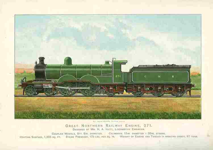
Includes No. 983 which had outside bearings on the bogie, and No.
271 which originated as a four cylinder simple ,but was rebuilt firstly as
an outide two cylinder locomtive with Walschaerts valve gear and then as
an inside-cylinder locomotive. These are illustrated. The large Atlantics
are also described, but not illustrated.
Maskelyne, J.N. Locomotives
I have known. London: Percival Marshall, 1959. 133pp.
No. 990 is illustrated..
Nock, O.S.
Great Northern 4-4-2 'Atlantics'. 1984. 136pp. (Classic
Locomotives No. 2)
Concentrates upon locomotive performance
Nock, O.S. Historical
steam locomotives. 1959. Chapter 10.
Obviously overtaken by later work.
Perceived with the benefit of a now very long hindsight the original Ivatt Atlantics had a marked similarity to the Sirling eight-foot singles: the long boiler coupled with outside cylinders: elsewhere boilers looked shorter and were frequently combined with inside cylinders. Groves (3A) pp. 163-87 cover the development of this class. A prototype (No. 990) was constructed: this had 18¾in x 24 in cylinders; a grate area of 26.75 ft2; 6ft 8in coupled wheels and 175 psi boiler pressure. They were fitted with balanced slide valves and the prototype was fitted with lever reverse. An unusual feature was that the connecting and coupling rod pins were turned with the big-end section ½in. eccentric to the inner section taking the coupling rod: this differential throw enabled the 24in piston stroke to be reduced 23in in the circle traced by the coupling rod, thus reducing stress in the rods at high speed.
The leading bogie was of the standard pattern with swing-link suspension. Nock notes that the design of the trailing-wheel mountings remained standard throughout the entire range of Great Northern 'Atlantics' and which he believed, was also used on the Marsh Atlantics on the LBSCR, was not a trailing 'truck' in the usually understood form. The spring, mounted externally on the supplementary frame-plate, rested on a plate that was free to slide over the top of the axle-box. There was no side control by springs or other means to keep the trailing wheels central when the locomotive was running on a straight road. As vehicles these 'Atlantics' rode well and were easy on the track.. Allen takes a completely contrary view (and is higly indicative of Nock's lack of reading skill): Allen stated that the Atlantics were prone to roll at speed, sometimes quite prodigiously. This was the product of several factors in combination. First was the lengthy frame, second the very tight spacing of the driving wheels-only 6 ft. 10 in., centre to centre, against a diameter of 6 ft. 7½ in.; in consequence flange depth had to be reduced from 11/8in. normal for wheels of this size to 29/32in., and a special type of brake hanger had to be devised to fit between the wheels. Finally the trailing axle was carried in fixed outside axleboxes, so that it had no lateral control, and little more check of side play came from the swing link leading bogie. Whatever the reasons, the crew were subjected to a vigorous lateral motion in the cab, the spartan shelter of which aggravated their discomfort.
According to Nock the boiler looked longer than it really was, because the leading end of the barrel was recessed by 1 ft 11 in, to provide an extension of the smokebox capacity and, although the overall length externally was 14 ft 8½in, the distance between the tube plates was no more than 13 ft 0 in. Aspinall did exactly the same on his L & YR 'Highflyers', with the same distance between the tubeplates; but although both friends used tubes of 2 in outside diameter, the Horwich boiler of larger diameter had 233 of them, against 191 on No 990. It was considered that the free gas area through the tubes, related to the grate area, was a measure — other things being equal — of the freedom with which an engine would steam. The Aspinall engine, with 26 sq ft of grate area, was the better of the two, with a ratio of 16:1, against the 13:1 of No 990; but the latter, fired on best quality, . hard, Yorkshire coal steamed well enough for all current requirements on the GNR.
Poultney's British express locomotive development considered that the principal dimensions of the Ivatt and the Baldwin Atlantics built for the Atlantic Coast Lines in 1894 were very similar: both had grate areas of 26ft2. "The Great Narthern Atlantic was not only based an American design in respect to the wheel and cylinder arrangements adapted, but contained also other features found in American practice, namely the swing-link pattern of leading bagie and semi-balanced Richardson pattern slide valves (Nock considered that only this last followed American practice). The slide valves were operated by Stephenson's motion and incorporated four strips let into four planed grooves on the back of the valve; these strips, projecting upwards, bore upon a plate held so as to be parallel to the valve face. The strips making contact with this plate were pressed up by springs. The area enclosed was under exhaust pressure only, because the back of the valve was kept in free communication with the blast pipe through a hole in the crown of the valve.
The prototype had 1¾in wide water legs in the firebox and this led to a rapid accumulation of sediment and 3in water legs were fitted on the production series. In June 1900 No. 990 was named Henry Oakley.
Twenty locomotives were ordered in January 1999, but subsequently this was reduced to ten turned out between March and June 1900. In January 1902 a further ten were ordered with rear-end framing capable of accepting wide fireboxes (but these were never fitted). These had screw reverse. The boiler was used as the basis for those fitted to the K1 0-8-0s and L1 0-8-2Ts.
Wintour, F. discussion on Hughes, George
Locomotives designed and built at Horwich with some results. Proc. Instn
Mech. Engrs, 1910, 77, 561-653. (via
Bulleid' Master builders of steam)
Presented at IME Meeting in Liverpool on 27 July 1909. Wintour, speaking
on behalf of Ivatt noted, "As Mr. Churchward has stated, it is absolutely
necessary there shall be some check on the lubrication which, if it once
gets slack, will cause a great smash on the engine. In one case where the
lubrication failed, the piston and the cylinder were quite broken up, and
we find it very necessary to have a reliable lubricator and a good cylinder
oil, with steam superheated to 650°F. If these precautions are not taken,
more cost may be incurred in five minutes than will be saved in two years."
Like many others, Ivatt patented an arrangement of steam pipes in the smokebox,
to provide a low degree of superheat in older engines where new tubeplates
were hard to justify: but their complication militated against their
advantage-they were mounted on trunnions to permit swinging them clear for
tube-cleaning.
Groves (3A) pp. 170-5 cover the development of superheating for this class (although some of the more general aspects of superheater development were considered when it was applied initially to the 0-8-0s). In October 1905 the Board was approached to seek the purchase of an American Loco. Co. superheater costing £250 and approval was receivedd on3 November 1905, but the purchase was not made. In 1906 the Schmidt type was evaluated on the 0-8-0s. In May 1909 No. 988 was fitted with an 18 element Schmidt superheater and the boiler pressure was reduced to 160 psi, piston valves fitted, and the cylinders were enlarged to 20in diameter. In February 1914 Gresley fitted Robinson superheaters to Nos. 982 and 986. In August 1914 consideration was given to fitting a Swindon superheater to the class, but no action appears to have been taken. The Gresley superheater was fitted to some and by 1924 all of the remainder had been fitted with Robinson type superheaters.
No. 988 was the subject of several experiments: with superheater dampers. Between February and August 1912 it was fitted with a Hill Patent locomotive furnace in which steam was discharged into special conduits below the grate. This device was also fitted to D2 class 4-4-0 No. 1311 and to some 0-8-0s.
In September 1903, No. 988, later No. 983 (Fig. 150) was fitted with a special bogie with outside frames (Groves 3 p. 177) and wagon-type axleboxes. The springing was also changed, but was later adjusted.
No. 252 was fitted with Notter's patented spark arrester in 1912, but the apparatus was ineffective in January 1913. No. 256 was fitted with Schleyder's Patent smoke consumer. Trials were made with Silvertown lubricators, but the Wakefield type was found to be cheaper and more effective.
Nock summarizing considered that on the lighter trains, like the 'Manchesters', via Retford, and the special 2:00 pm up from Leeds there was plenty of fast running; but it was only on special occasions, when Mr Ivatt himself or other high dignitaries of the GNR were travelling, that the engines of both varieties were exerted uphill. It was still a time when drivers had their own engines and they took pride, not only in immaculate appearance but in reliable mechanical performance; and while not out of balance to the same extent as the larger boilered class, so far as disparity between boiler and cylinder power was concerned, the 'Klondikes' were not powerful engines by the standards of the early 1900s. Cecil J. Allen summed them up, in 1914, as 'curiously variable engines, as far as performance goes; at times they can be record-breakers of the first water, but on other occasions they are unaccountably sluggish'. Sluggish is perhaps not quite the correct term to use for these engines, because it might suggest some inherent weakness, such as a restriction in the steam circuit that induced unduly high back pressure. This was certainly not the case with any of Ivatt's engines. Instances when they seemed to be 'dragging their feet' would almost certainly be due to the temperament of the driver, who was disinclined to hurry. It would equally not be due to any shortage of steam, for the 'Klondikes' were excellent in this respect.
Allen seemed content in retrospect to note his recollections to be dominated by their merry chirrup when working hard and the absence of any flurry of rods and motion at speed. The combination of short stroke and an unusual arrangement of eccentric crankpins gave the engines an economical gait that always made their pace look effortless. Doubtless to reduce stress on the rods at higher speed, the crankpins were turned to differing, eccentric diameters, so that the coupling rods traced a diameter an inch less than that of the stroke. If the intent was as suggested, the concept was certainly successful, for overheated big ends were a rarity both on the "Klondykes"
No. 271 experimental 4-cylinder locomotive
Groves (3A) 182-3 and Figs 156-8 cover the locomotive constructed to test four-cylinder propulsion with four 15in x 20in in-line cylinders which drove the leading coupled axle. As constructed it had Stephenson link motion and piston valves. In 1903 it was rebuilt with Walschaerts valve gear and balanced slide valves. In 1911 it was rebuilt with two inside cylinders, piston valves and Stephenson link motion and ran in this form until withdrawn in June 1936. Further information is given about this unique locomotive in RCTS Locomotives of the LNER Part 3A (pp. 59-61 and Figs. 46/7). Macnair Backtrack, 2012, 26, 756 suggests that the design may have been intended to reduce slipping by improving the torque pattern on starting..
Preserved No. 990 Henry Oakley
Groves (3A) 186-7 cover the preservation of No. 990 at York Railway Museum from 21 January 1938 and its emergence in the summer of 1953 to work the Plant Centenarian specials with the preserved No. 251.
Contemporary
Supports for wide fireboxes, G.N.R. Locomotive Mag., 1908, 14, 32. diagram
Allen, Cecil J. British
Atlantic locomotives, revised & enlarged by G. Freeman Allan..
1976.
Allen, Cecil J. A famous locomotive Class: the Great Northern Atlantics.
Trains Annual 1948,
68-74.
Checkley, Sid. Memories of Colwick.
in Hughes, Geoffrey.
A Gresley anthology. Didcot: Wild Swan/Gresley Society, 1994.
pp. 77-82.
Fitter at the end of WW2 and thereafter. The Ivatt Atlantics were
then very run-down, and difficulties were experienced with maintaining the
balanced D-type valves which were heavy. To remove the driving wheels involved
disconnecting all the service pipes which ran underneath.
Fullagar, L.A. Comparison of slide bar pressures.
Trans Instn Loco. Engrs., 1915,
5, 1-10. + 4 plates (diagrs.) (Paper No. 34)
The engine types selected were the GWR County class and the Great
Northern large Atlantics. The former, with other of the Great Western 30in.
stroke classes, were those whose oscillation at starting was noticed. The
latter, which represent the other extreme in connecting rod and stroke ratio,
are amongst the steadiest running engines known to the Author. For the purpose
of comparison an ipdicator diagram was taken belonging to what may be termed
a neutral engine of not dissimilar dimensions, LTSR 4-4-2 tank of the No.
80 class, now MR Nos. 2176-9.
Gresley, H.N. discussion on R.P. Wagner Paper
J. Instn Loco. Engrs, 1935,
25, 275.
Another thing is why have you such a very small superheater—24
elements—on that great big engine? We have heard it suggested here that
one of the important. things is to get high superheat. I have 42 elements
in my engine, nearly double the number and do not get a very high degree
of superheat. As for 800°F. superheat, Lord Monkswell may not be aware
that 15 years ago we were runnmg engrnes on the Great Northern Railway with
800°F. of superheat—the old Atlantic engines wIth. a 32 element
superheater; that is when they were working pretty hard. I often observed
over 800°F. indicated by the pyrometers; it may be suggested that the
pyrometers were not quite correct. I had them checked and rechecked before
and after, and they were correct. So there is nothing unusual in 800°F.
of superheat.
Harvey, D.W. Bill Harvey's
60 years of steam. 1986.
Page 13: H.G. Ivatt told Harvey on the last run of the C1 in 1950
that the cost of the original large Atlantic had ben £2548 in
1902.
Maskelyne, J.N. Locomotives I have known. London: Percival
Marshall, 1959. 133pp.
No. 1442 is illustrated. In the accompanying text it is noted that
some of their performances must rank for ever among the very finest exploits
ever recorded by steam locomotives...
Nock, O.S. Great Northern
4-4-2 'Atlantics'. 1984. 136pp. (Classic Locomotives No. 2)
Concentrates upon locomotive performance, but on page 83 Nock stated
that he had often wondered whether Gresley had considered an experimental
three-cylinder rebuild with conjugated valve gear, especially as the
four-cylinder rebuild did not appear to be entirely successful
Nock, O.S. Historical
steam locomotives. 1959. Chapter 10.
Obviously overtaken by later work.
Tuplin. W.A. Reflections on firing an Ivatt Atlantic.
Trains Annual, 1965,
16-19+
Author fired one on the stretch between Nottingham and Sheffield and
noted that the grate was very large. Also commented on the high speed with
high load achieved by No. 4404 when it substituted for an A3 Pacific. The
high power output between Barkston and Selby was especially noteworthy.
Groves (3A) pp.188-232 cover the development of the large Atlantics, with a digression between page 205 and about page 213 to examine 4-cylinder compound (and four-cylinder simple) designs. Groves also dwells at considerable length on the mysterious Grantham accident on 9 September 1906. This happened to involve an Ivatt Atlantic, but was probably due to some emergency on the footplate (such as the sudden collapse of the driver): Nock also considers this accident at some length. At the end of this digression booster experiments on No. 1419 begin on pages 213-15 to be continued as part of the LNER story. Those who saw the small and large Atlantics coupled together must have found it difficult to associate the closeness of the two designs. The larger boiler transformed the appearance in a far greater way than that made in the rebuilt Royal Scots (where the new boiler looked smaller), for instance. The earlier Atlantics could be perceived as enlargements of the Stirling singles (van Riemsdijk actually states this on page 54, whereas the new Atlantics (as Poultney makes abundantly clear) belong to the twentieth century. Ivatt's own response to a Midland compound design submitted by Robert Stephenson is most interesting (and makes early locomotive development on the LMS appear to even more extraordinary). Moreover, Poultney incorporates a table from Churchwards's classic paper on large locomotive boilers which includes the Ivatt large Atlantic which had the greatest grate area of any in the table.
No. 251
Groves (3A) pp. 190-5 note that the prototype was the subject of draughting trials both before the production series began and following their introduction to further experiments by Bulleid when the locomotive was fitted with a stovepipe chimney, This locomotive was fitted with lever reverse as were the succeeding locomotives, although Groves fails to make this clear. Indeed there is little justification for giving especial prominence to No. 251. A batch of twenty followed in 1904 Further batches followed and the final batch of 1910 was superheated and fitted with piston valves. If the Vulcan locomotive is included then the total of large Atlantics built was 94.
Atkins, Philip. Crewe at home and
away. BackTrack, 1989, 3, 11-80.
Includes results from the 1909 comparative tests against a GNR
large Atlantic between King's Cross and Leeds and between Euston and Crewe;
and with McIntosh Cardean type between Crewe and Carlisle and between Carlisle
and Glasgow: illus shows 1405 City of Manchester at Glasgow Cnetral
and 903 Cardean alongside Crewe Works; Ivatt 1449 on fourteen coaches
south of Crewe
Brewer, F.W. The Great Northern Atlantic type express locomotives.
Loco. Rly Carr. Wagon Rev., 1923, 29, 329-33; 362-5: 1924,
30, 15-17; 50-3. 14 illus.
A detailed technical history of pre-1923 development.
Churchward, G.J. Large locomotive
boilers. Proc. Instn Mech. Engrs, 1906, 70, 165-75. Discussion:
176-255.
Significantly Churchward included the Ivatt large Atlantic in a table
of "large locomotive boilers", although he questioned the usefulness of the
type within the British context.
Nock, O.S. British locomotives
of the 20th century. Volume 1. 1900-1930. 1983.
Page 81: general arrangement drawings: side elevational cross section
and plan.
Scott, Ron. G.N. Large Atlantics in Reed, B. Locomotives in profile; No. 30. Volume 3 pp. 125-48
Experimental locomotives
Van Riemsdijk's Compound locomotives notes that the Great Northern Railway had three experimental four-cylinder compound Atlantics, "none of which achieved any distinction, but which perhaps merit inclusion in the historical record" (it is worth noting that Riemsdijk only appeared to be interested in locomotives which added to the overall development of compounding).
Ivatt, Henry A. Notes on road trials of three express
passenger-engines, carried out on the Great Northern Railway in 1906.
Proc. Instn Mech. Engrs., 1907,
72, 525-32.
With No. 1300 (a four-cylinder compound); No. 292 (combined 4-cylinder
compound or simple) and No. 294 (2-cylinder simple). All were Atlantics.
Nock considered these tests to be
highly inconclusive., but were
reproduced in his book on the class.
No. 292 (four-cylinder compound)
No. 292 entered service in March 1905. "The design of this locomotive
was distinctly odd. While it was superficially very similar to a standard
Atlantic, the evident desire for this similarity resulted in the inside cylinders
having extremely short connecting rods, only 4ft 8in between centres. As
the piston stroke was 26in the angularity of these rods was acute, but
fortunately the inside cylinders had separate valve gear (Stephenson's),
the outside cylinders having Walschaert's. It would have seemed normal to
make the low pressure cylinders at least as large as the cylinders of a standard
two-cylinder simple, but in fact their diameter was only 16in as against
the 19in of the standard engines at that time. The high pressure outside
cylinders were 13 inches in diameter and to achieve a volume ratio of
approximately 1: 2 between high pressure and low pressure sides the high
pressure stoke was only 20in. The boiler pressure was 200psi although the
boiler had actually been designed to withstand 225psi. This engine lasted
longest of the three compound Atlantics, in compound form. It was broken
up in 1928 without having received any significant modifications, not even
a superheater.
Nock in his British locomotives of the twentieth century Volume 1 (page 90) noted that he came across the only details he had ever seen about the working of this engine quite accidentally, in the Darlington drawing office of the former North Eastern Railway. In 1953 he was browsing through some tests made in pre-grouping days with the NER dynamometer car, and came across a test made in 1909 with the new East Coast Royal Train, prior to a visit to Edinburgh by King Edward VII, and it began at Doncaster. The test was primarily to record the rolling resistance of the new train, and so did not include any details of the engine working. This was unfortunate, for the GNR locomotive was No 1421 and the performance was spectacular to a degree. The load was 302 tons behind the tender, and with this a speed of 60 mph was attained in 4¾ miles from the start; and then, gradually working up to a sustained speed of 73 mph on the level the train passed Selby, 18.4 miles, in the unprecedented time, for that period of 19½ minutes. Checks spoiled the continuation of the run to York, where the North Eastern Railway took over the haulage. This run is also recorded on page 48 of Nock's monograph on the Ivatt Atlantics where it is noted that a drawbar pull of 1½ tons was registered at 70 mile/h.
Illus (p. 79) Riemsdijk "Action pictures of Ivatt's first compound GN Atlantic are rare."
Le Fleming, Hugh M.
International locomotives, Plate 34
Painting of locomotive backing down to King's Cross
Groves (3A) page 206 notes that the GNR Board
sought a wide range of proposals for designs, including compounds, from outside
builders:
see also Gresley page
| Manufacturer | Type | Comments |
| Beyer Peacock | 4-6-0 | Al (7ft 0in. wheels and 20in. by 28in. cylinders); A2 (6ft. 3in. wheels and 20in. by 26in. cylinders). |
| 2-6-2 | A3/4 alternative design | |
| 2-4-4 | A5 (7ft 0in. wheels): all Beyer Peacock simple expansion | |
| Vulcan Foundry | 4-6-0 | B1 4-cylinder de Glehn compound with 6ft. 7½in. wheels. 225psi boiler pressure. Weight 73½ tons. |
| 4-4-2 | B2 4-cylinder de Glehn compound with 6ft. 7½in. wheels. 225 psi boiler pressure. Weight 72 tons. | |
| N.B. Loco. Co. | 4-6-0 | C1 4-cylinder compound. (firm also produced schemes for a 4-cylinder compound 4-4-2 and a 3-cylinder 4-6-0 which were not considered) |
| R. Stephenson | 4-4-0 | 3-cylinder engine based on the Midland Railway compounds. |
| Kitson | 4-6-0 | El/2 compound and E3/4 non-compound, with alternately 190 psi and 210 psi boiler pressures. |
Alexander Ross, the Civil Engineer, was involved and many of the designs were dismissed as either being too heavy or too long. The MR compound type offered by R. Stephenson was dismissed by Ivatt as lacking sufficient power, and Oliver Bury persuaded the Board to accept the Vulcan 4-4-2 design, and this required modification to meet GNR requirements. Groves (3A) notess that Serve tubes were fitted and that the intended Belpaire firebox had to be replaced by a narrow firebox with a raised configuration.
Riemsdijk noted that No. 1300 was the proposal of the Vulcan Foundry on the basis of an approach made by the Great Northern directors to some locomotive manufacturers in 1904. This engine, No.1300, is better known than No.292, perhaps because it underwent several transformations and acquired an exceedingly bad, though deserved, reputation. In the discussion following the second part of the author's paper to the Newcomen Society, W.O. Skeat gave, an amusing account of the troubles of No.1300. It appears that it was impossible to ensure the steam tightness of the various joints of the smoke box and around it, a condition arising partly from the unsatisfactory design of the pipework itself but also from the fact that this engine had a de Glehn/du Bousquet cylinder layout but lacked the very important bracing of the frames employed in French practice. As a result the front end was too flexible. This problem was never cured. Early in Gresley's regime the engine was superheated and some alterations were made at this time in the other front end arrangements but these did not suffice and in 1917 Gresley rebuilt it as a two-cylinder simple. This involved a fairly substantial redesign: even the wheelbase was altered, and the result was a less ramshackle looking machine. However, the engine was still not satisfactory and was scrapped late in 1924.
The Vulcan Foundry had at least copied fairly closely the French cylinder dimensions and the volume ratio between high and low pressure sides was 1: 2.7. All four cylinders had a common stroke of 26in. The inside, low pressure cylinders had a diameter of 23in and the outside, high pressure cylinders had a diameter of 14in. There were four sets of Walschaert's valve gear. It is best to sum up the original design of No.1300 as a crude imitation of a Nord Atlantic.
Contemporary
Great Northern Ry.
Locomomtive Mag., 1905,
11, 129.
Accompanying illustration shows then new four-cylinder compound express
locomotive recently completed by the Vulcan Foundry, Ltd., which bore No.
1300 (WN 2025). It had many features of resemblance to the de Glehn type.
The h. p. cylinders were placed outside, and had piston valves on top, actuated
by Walschaert gear. The h.p. and l.p. reversing gears were independent. The
coupled axles were spaced further apart than in the standard G.N.R. Atlantks,
in consequence the wide firebox of the 251 class had not been adopted, but
the firebox shell was raised and had a larger diameter than the boiler barre1.
The leading dimensions were: h.p. cylinders 14in. by 20in; l.p. cylinders
23in. by 26in.; diameter of driving wheels, 6ft. 8in., total heating surface
2514 ft2.; grate area 31ft2; working pressure 200
psi.
The compound locomotives of the G.N.R.
Loco. Mag., 1908, 14,
89-90. 3 diagrams (side elevations)
Comparison of the dimensions of the de Glehn dimensioned Vulcan
Foundry locomotive No. 1300 with those of the more "Ivatt" dimensioned (smaller
cylinders) of the Doncaster built Nos. 292 and 1421.
Bazin, J.R. discussion on Selby, F.W.
Compound locomotives. J.
Instn Loco. Engrs., 1931, 21, 99-101. (Paper No.
257)
experience of the Ivatt experiments with the Vulcan Foundry de Glehn
type compound: condensation was experienced in the low pressure cylinders
on the GNR compounds..
No. 1421 (four-cylinder compound)
Groves (3A) 210-11. Riemsdijk: The third compound Atlantic was No.1421 which appeared in 1907. This was again an Ivatt engine and closely followed the Atlantic's design. The outside, high pressure cylinders were almost identical to those of No.292 but the inside, low pressure cylinders were enlarged to a diameter of 18in, this being made possible by their valves being placed on top of them instead of between them. The volume ratio was thus increased to roughly 1:2.5. The boiler pressure was again 200psi as in the other two compound Atlantics. Not surprisingly, this engine was an improvement on No.292 and the rearrangement of the low pressure cylinders resulted in a layout of pipe-work which made it an easier matter to fit a superheater and this was done in 1914. But it remained less satisfactory than the standard Atlantic and gave a fair amount of mechanical trouble so in 1920 it was rebuilt with two cylinders and piston valves to match the other Atlantics which were being converted from slide to piston valves in this period.
Results of trials in 1906 communicated (without comment) to Instn Mech. Engrs.
| Locomotives | No 1300 | No 292 | No 294 |
| Miles run, engine | 11,286 | 11,670 | 11,673 |
| Miles run, train | 11,405 | 11,415 | 11,415 |
| Speed, average, mph | 49.02 | 49.9 | 49.58 |
| Weight of train, average, tons | 229.98 | 238.03 | 234.29 |
| Ton-miles | |||
| Total train | 2,540,130 | 2,717,112.5 | 2,674,420 |
| Including engine and tender | 3,803,030 | 3,993,812 | 3,949,110 |
| Per hour, engine and tender | 16,759 | 17,337 | 17,030 |
| Coal used | |||
| per engine-mile, lbs | 44.86 | 43.02 | 44.31 |
| per train-mile, lbs | 45.84 | 43.98 | 45.31 |
| per ton-mile, lbs | 0.133 | 0.126 | 0.131 |
| Oil used | |||
| per 100 engine-miles, pints | 7.34 | 7.18 | 6.22 |
| per 100 ton-miles, pints | 0.022 | 0.021 | 0.0184 |
| Costs | |||
| Coal | |||
| per engine-mile, pence | 2.4 | 2.3 | 2.37 |
| per ton-mile, pence | 0.0071 | 0.0067 | 0.007 |
| Oil | |||
| per engine-mile, pence | 1.165 | 0.16 | 0.14 |
| per ton-mile, pence | 0.00049 | 0.00047 | 0.00041 |
| Repairs | |||
| per engine-mile,. pence | 0.56 | 0.45 | 0.37 |
| per ton-mile, pence | 0.0017 | 0.0013 | 0.0011 |
| Total | |||
| per engine-mile, pence | 3.125 | 2.91 | 2.88 |
| per ton-mile, pence | 0.0092 | 0.0085 | 0.0085 |
It is generally agreed that superheating transformed the performance of the large Atlantics. Nock in his monograph on the Ivatt Atlantics (Chapter 5) gives a somewhat wayward account of the application of superheaters of various types to the class and cites an article by J.R. Bazin in Rly Mag. for "1911" (somewhere in its 1200 pp in 2 volumes). On page 58 there is a diagram of the superheaters originally fitted to the 1452-61 series and on page 63 of the Gresley twin-tube superheaters fitted to the H2 class 2-6-0s fitted to three small Atlantics and to ten of the larger type. The data relating to the various boiler/superheater types is summarized in a table on page 13 of RCTS Locomotives of the LNER Part 3A.
Exhaust steam injectors
G.W. Phillips J. Instn Loco
Engrs, 1950, 40, 670-1 in discussion on paper
by T.H. Shields noted his experience of the exhaust steam injector c1909?
with Ivatt Atlantic superheated boilers fitted to Nos. 1452-61
Exchange trials against LNWR Precursor class
In June 1909 there were month long trials between Euston and Crewe and Kings Cross and Doncaster of two Ivatt Atlantics against two members of the Precurosr class (the locomotives selected were restricted to one or othe routes for the trials. The trials lasted one month and both types of locomotive performed well. These tests are briefly summarized by Allen (p. 18-19) and on page 48 et seq by Nock who notes the involvement of Ivatt's son in the tests whilst he was working as a junior engineer at Crewe. Nock gives more extensive details of the tests than Allen.
Performance
Rous-Marten, Charles British
locomotive practice and performance. Rly Mag., 1903, 13, 124-31.
Describes special journey made on 1 July 1903 between Leeds and Kings
Cross behind No. 253 performed in 3hr 20min from Holbeck to Kings Cross with
a stop at Wakefield.
The most astounding performances occurred late in the history of the class when Atlantics were called upon to deputise for failed Pacifics. Runs recorded by C.J. Allen and by A,F. Webber (but not credited by Allen) are reproduced on page 31 in Allen's British Atlantic locomotives: these both involved the haulage of very heavy trains between Grantham and York and were performed within the schedule. Nock (p. 107) also records a run from Doncaster to Kings Cross behind No. 4452 on the Silver Jubilee when the further loss of time was minimized through hard running. The best of the everyday Atlantic performance was on the Pullman services bewteen Leeds and Kings Cross during the early 1930s and the best of this is recorded in Chapter 10.
No. 279
Groves 211-13 this was a substantial rebuild under Gresley in anticipation of his Pacific designs and is considered as a Gresley locomotive.
Groves (3A) notes (p. 127) that Ivatt was responsible for 136 6ft 8in 4-4-0 passenger locomotives constructed between 1896 and 1911. These belonged to three classes: GNR D1, D2 and D3. The first type was derived from the Stirling 2-4-0s but was fitted with a swing link bogie and 4ft 5in domed boiler. 51 locomotives of this type were constructed between 1896 and 1899. A larger boiler was developed in 1898 and this was fitted to seventy new engines between 1898 and 1909. The final class of fifteen emerged in 1911 and these were built with piston valves and superheaters. As usual there is confusion between the GNR and LNER classifications.
This type was originally envisaged as a 6ft 6in 2-4-0, similar to the Stirling type, but with a 4ft 5in domed boiler, and approval for twenty of these was obtained on 27 July 1896, but a prototype 4-4-0 emerged later in 1896, and a batch of ten followed in 1897 and fifty one had been constructed by 1899. Like the Ivatt singles the bogies suffered from fractures and thicker bogie frames were substituted. These became GNR class D2, and when rebuilt with 4ft 8in boilers became class D3. Rebuilding with larger boilers continued after the Grouping. Extended smokeboxes were fitted to some of the locomotives which retained the smaller boiler. Withdrawal of the unrebuilt locomotives began in 1935, but some of the reboilered locomotives lasted into the BR period. Groves (3A) pp. 128-38. Page 133 notes that Driver Plumtree of Lincoln invented a spark arrester and this was fitted to No. 1313 for a few months trial in 1910..
Four-coupled bogie express engine for the Great Northern Railway. Locomotive Mag., 1895, 2, 45. illustration
In 1898 a 4-4-0 with a larger boiler than the 400 type was introduced: the grate area was approximately 17% larger. A total of 70 was constructed between 1898 and 1909. Groves 3A pp. 139-55 describe this class. No. 1331 was fitted with J.T. Marshall's valve gear, but the experiment lasted for only about six months. Nos. 1384 and 1385 were fitted with Drummond spark arresters (Groves 3A p. 140). No. 1383 was fitted with a Baldwin superheater of the Vauclain type (this involved an extended smokebox see Groves Fig. 123: No. 1383 at Boston in 1911) and No. 1319 was fitted with an Ivatt combined U-tube superheater and spark arrester. No. 1381 was the only member of the class to receive a conventional superheater in GNR days (this was under Gresley and was of the Robinson type).
Four-coupled bogie engine, Great Northern Ry.
Locomotive Mag., 1896, 3,
137. illustration
No. 1326 extended smokebox
G.N.R. loomotives.
Locomotive Mag., 1896,
3, 161
Later use
Hardy, R.H.N. Steam in the blood. page 70
"The Joint men [at South Lynn] thrashed work out of these old things that
had not been coaxed out of them for many a year on their own territory".
Then notes that the pioneer locomotive No. 3400 was one of the "wildest riders"
he had travelled on up to that time and at speed was "downright dangerous"
McKillop, N. The lighted
flame. 1950.
"When running at speed they had the most diabolical and varied repertoire
of bangs, thuds, jerks and jumps of any locomotive I have ever stood
on"
Groves (3A pp. 155-63) describes the fifteen locomotives supplied in a single batch: they had superheaters and piston valves and shared the same boiler as the J21. J22 and N2 classes. Nos. 60 and 61 were built with Ross pop safety valves. They had screw type reversing gear. For a time they were used on light Leeds to King's Cross dining car trains. Fig. 1145 shows No. 60 on a heavy down express at Wood Green in about 1912. Towards the end of the GNR the class worked expresses to Cambridge and leave trains from RAF Cranwell.
4-2-2 singles: classes A4 and A5
Groves (3A) pp. 114-26 cover the final 4-2-2 singles to be manufactured for use on a British mainline company. They had similar front ends to the Stirling 7ft 6in singles (and shared their driving wheel size), but had bigger boilers. No. 266 constructed in 1898 had 18¼ in bore cylinders (later 18½) and was classified as A4 whilst No. 267 of 1900 and the batch of ten in 1901 had 19in (later bored out to 19¼ to 20in) cylinders (all had 26in stroke) with balanced slide valves. Interestingly the Locomotive Mag. (1905 15 May) could write that a new series of single was "contemplated" at Doncaster. All were withdrawn in 1917. Investigations performed by Ivatt in 1904 on the 0-8-0s and on the 4-2-2s showed that in the case of the former drawbar pull declined to a low level at 40 mile/h whilst a similar state was reached with the singles at 80 mile/h: in both cases this was due to internal resistance. The singles were capable of a drawbar pull of 3 tons at 20 mile/h. In 1910 No. 265 was fitted with Ivatt's patent crank axle and Joy valve gear (the only use of this valve gear by the GNR) (Grove 3A p. 120). They appear to have been happiest on the light competitive expresses which the GNR ran to important places like Bradford, Cromer (via West Runton) and Manchester. On the other hand, they were sometimes entrusted with heavy Royal Trains. A speed of 88½ mile/h was achieved between Little Bytham and Essendine by No. 268 on 20 December 1902 whilst hauling an up Scottish express. Fig. 108 shows No. 269 on the 10.35 King's Cross to West Runton (and Cromer) express at Peterborough on 29 July 1914.
Contemporary
G.N.R. locomotives. Locomottive
Mag., 1898, 3, 161.
Great Northern engines. 172.
New bogie single express locomotives stationed at Grantham: Nos. 92,
100, 261 and 262 (WN 934-7) and Nos. 103-4 (WN 938-9) at London.
Rous-Marten, Charles British
locomotive practice and performance. Rly Mag., 1903, 13, 124-31.
Describes special journey made on 1 July 1903 between Kings Cross
and Doncaster behind No. 261 non-stop in 2hr 47 min..
Ivatt passenger tank engines
The suburban routes to the Northern suburbs, notably the line from Finsbury Park to High Barnet, were steeply graded and attracted heavily loaded trains. Electrification was considered but rejected on the ronds of cost, and rather in the manner of the Great Eastern Decapod a high accelaration steam locomotive was conceived. This was an 0-8-2T No. 116 completed on 11 June 1903 and was a tank engine version of the K1 0-8-0 class.
Great Northern Railway eight-wheel
coupled tank engine. Rly Mag., 1903, 13, 369.
Official photograph of No. 116 in photographic grey, leading dimensions
and intended use for suburban traffic over heavy gradients.
The Civil Engineer considered that the weight (79 tons) was excessive and the locomotive was returned to Doncaster for rebuilding with a smaller boiler and shorter side tanks. This reduced the maximum axle load from 17 tons to 15¼ tons without greatly damaging performance. Three batches were constructed between 1904 and 1906 to give a total of 41 locomotives, but only the first eleven were fitted with condensing apparatus. The non-condensing locomotives were sent either to Colwick or to the West Riding and were joined by the eleven from London in 1907. From 1909 the class was re-equipped with the original type of boiler, but this programme was not completed until after the Grouping. This transfer led to a surplus of the small boilers and in 1913 Gresley introduced the J23 class of 0-6-0Ts to exploit these boilers (p. 75). Seven locomotives were fitted with superheaters (pp. 76-9): four received he Robinson type, two the Schmidt type and No. 131 with a Gresley twin-tube superheater. The entire class was withdrawn by 1934. Groves (3A) pp 69-86 cover the whole life of the class and this may be supplemented by the RCTS Locomotives of the LNER Part 9B pp. 12-21 which complete their relatively brief existence under class R1. Goslin, Geoff. Steam on the Widened Lines. Volume 1: The Great Northern and Midland Railways and their successors. 1997 includes pictures of locomotives in service on London suburban trains. A diagram on page 18 shows the proposal to rebuild the locomotives with diesel engines and compressed air transmission. Robin Barnes illustrates this proposal in his Locomotives that never were (pp. 58-9).
The superheated locomotives were used for a time on Colwick to Peterborough coal trains. In 1919 some of the locomotives returned to London to handle empty stock trains. They were very successful at this task and Groves mentions the distinctive "bark" which characterized their progress. The originally intended task of King's Cross suburban services failed due to their excessive weight and length causing problems at Moorgate and their sluggish overall performance on the faster mainline suburban services. During the period of coal shortage in 1921 Gresley equipped No. 131 with the Scarab system of oil-firing see Topham, J. Instn Loco. Engrs., 1935, 25 Paper 345, .
Eight wheels coupled side tank locomotive, G.N.R. Loco. Mag., 1903, 9, 83-4. illustration, diagram (side & front elevations)
Eight-coupled radial tank locomotive, G.N.R.
Loco. Mag., 1904, 10,
32. diagr. (s. el.)
diagram of modified form
[GNR 0-8-2T]. Loco Mag.,
1909, 15, 106
illustration of No. 144
0-8-2 superheater tank locomotives, Great Northern Ry.
Loco. Mag., 1917, 23,
217-19. illustration, diagram (side elevation)
Gresley modifications
[GNR 0-8-2T modified to burn oil fuel].
Loco. Mag., 1921, 27,
140
No. 131: Scarab system
The 0-8-2 tank engine. Loco. Mag.,
1941, 47, 131.
cites earlier Locomotive Magazine references:
9, 83
10, 32
15, 106
23, 140 Scarab oil firing
Groves (3A) pp. 86-98 cover the Great Northern history of this design which like the L1 0-8-2T began with a prototype No. 190 which proved to be unsuitable for working into Moorgate. Figures 74 and 75 show No. 150 in its original condition with its side tanks extending beyond the middle driving wheel splashers. RCTS Locomotives of the LNER Part 9A Fig. 37 shows it still in this condition at Hatfield lettered LNER before the removal of its condensing gear in 1927. In 1906 a 2-6-2T design had been considered (the LMS eventually used this type into Moorgate but with shorter trains). Fifty five of the modified design were constructed between 1907 and 1912 and were fitted with condensing gear. They were highly successful on the London suburban services, but suffered from excessive flange wear on the leading wheels. Like their counterparts in the Welsh Valleys the N1s worked downhill with the radial wheels at the front.
Francis Wintour was involved in design of N1 class (where his earlier experience at Kings Cross was useful): alleged to have said "That's what I call a good engine (Bulleid' Master builders of steam page 42)
N1 boilers were also fitted to some 4-4-0s and 0-6-0s, but were not necessarily interchangeable, depending on the height of the dome casing. However, the 4-4-0s turned out in 1909 also had the shorter 2ft. 2in. high dome casings with their boilers although they were hidden under tall dome covers. The height of the dome casing on new N1 boilers was reduced to 1 ft. 11¼in. from 1911 to make it correspond with the superheated class J22 0-6-0s introduced in August of that year. There were no external differences with these later N1s as the usual dome covers were fitted and the height remained unchanged on all the saturated and 18-element superheated boilers until after Grouping. Washout plugs were fitted on the sides of the firebox. In Grouping days these were replaced by two inspection covers on each side when new firebox casings were required and when the engines were fitted with new boilers. Goslin, Geoff. Steam on the Widened Lines. Volume 1: The Great Northern and Midland Railways and their successors. 1997: several illustrations in natural haunts. .
Superheating:
No. 1598 received a Schmidt-type superheater in February 1918: this had remained spare since January 1913, after removal and replacement by a Doncaster-type on Gresley's J22 0-6-0 No. 542. No. 1598 was fitted with balanced slide valves and a mechanical lubricator. The heating surface particulars differed slightly at first from standard. The engine was tested in the London area during 1918-19 alongside Groves stated 3-cylinder (but this is clearly incorrect) 2-6-0 No. 1646 (H2 class see Groves 3B page ) on trials with High Barnet trains; this led to the Gresley N2 class which differed from the superheated N1 primarily in the fitting of piston valves instead of balanced slide valves. In May 1922 Gresley compared the average coal consumption of No. 1598 with that of the remaining members of the class in the London area. The latter burned 64.4 lb. per mile against the superheated engine's figure of 52.3 lb. (Fig. 83 shows No. 1598 at King's Cross in February 1919).
In December 1922 a second N1, No. 1557, was superheated using second-hand Schmidt-type equipment. Unlike No. 1598 the original slide-valve arrangement was retained. The. two N1's with Schmidt superheaters were converted to the Robinson-type after Grouping. Additionally five new boilers with Robinson superheaters were ordered in 1922 but these, together with four others, were fitted after Grouping so that a further nine N1s received this type of superheater between February 1924 and June 1928. All these later conversions as in the case of No. 1557 retained their original slide-valve arrangements. On the superheated engines vertical twin "pepper-pot" -type anti-vacuum valves were fitted behind the chimney instead of the standard "mushroom"-type usually found on Gresley engines.
Gresley, H.N. Discussion on Hookham, J.A. Comparison between superheated
and non-superheated tank engines. J.
Instn Loco. Engrs, 1922, 12, 613-16
Gresley commented on the use of snifting valves, and his own experience
of superheating on 0-6-2Ts (includes side elevation of N1 0-6-2T No. 1598),
Details
A constructional detail applicable to the whole class as built was
the fitting of 1ft. 6in. long buffers with thin bases. Afterwards, to afford
adequate protection, a 1½in. thick packing ring was inserted between
the base and bufferbeam. The bunker tops were flared out, making the distance
across the coal rails 8ft. 6in. and therefore 1ft. 4in. wider than the cab.
This difference in width called for plates at the front of the cab keyhole
to deflect sparks and prevent them from being drawn into the cab. The spark
plates were 1ft. 2in. deep on Nos. 1551-60 and 1ft. 6in. on the later engines.
No. 190 was fitted before alterations had been made to its original cab.
It then received a spark plate 10in. deep (Fig. 75). Except for No. 190,
the usual step bracket was provided on the fireman's (left-hand) side of
the bunker to assist in climbing to the top of the bunker, with a short handgrip
later fitted high up on the cab side though the actual position and angle
of this handgrip varied. An extra handrail was fitted around the bunker shortly
after Grouping. The windows at the back were 1ft. 6in. diameter except on
Nos. 1561-70 which were fitted when built with surplus 1ft. 2in. frames taken
from stock. Protection grids comprising five vertical bars (four in the case
of Nos. 1561-70) were fitted over the windows to prevent breakages.
Conforming to usual Ivatt practice the driving wheels had helical bearing springs whilst the leading and trailing coupled wheels had springs comprised of nine plates 4in. wide and 5/8in. deep at 3ft. 6in. centres, but from early 1920 new sets having fourteen ½in. plates and one 5/8in. plate superseded the original specification. The engines were built with ordinary siphon oil boxes and displacement lubricators were provided for the cylinders. On No. 190 the latter were located on the smokebox front plate one at each side below the door. On the later engines they were fitted on the sides of the smoke box but the pioneer engine was not brought into line until Grouping days. The vessels were removed from the superheated engines which were instead fitted with a Wakefield mechanical lubricator on the right-hand side behind the front splasher.
Unlike earlier Ivatt classes, the handrail on the smokebox door was positioned just below the top hinge strap. From early in 1920 however the handrails were gradually repositioned above the hinge straps because the original position was too close to the door locking handle. Destination board brackets were fitted to the smoke box doors and on the rear of the bunkers on the engines in the London area. These were generally removed from the engines transferred to the provinces. When new No. 190 had the whistle above the cab roof, the top being only just within the Metropolitan load gauge. Curiously on both occasions when the engine was transferred from London to the West Riding a longer stem was fitted and the height to the top of the whistle was shown as 12ft. 11¾in. on the engine diagrams. On all the later engines the whistle was in front of the cab.
Steam-operated sanders for forward running were fitted in front of the leading coupled wheels and gravity sanders for reverse running behind the trailing coupled wheels. On the superheated condensing engines the inclusion of the header to the superheater required the chimney and blastpipe to be positioned further forward. This in turn made it necessary to reposition the condensing pipes likewise and so the tops of the sandboxes in front of the leading splashers were shortened by 4in. to accommodate them. Most if not all of the engines concerned retained the shortened sandboxes when the condensing gear was later removed.
During a General repair from 20th April to 15th July, 1910 Ivatt fitted No. 1556 with experimental condensing pipes. Instead of the usual form of one large pipe either side, each was split up into a "nest" of smaller diameter ones, like the inside of a surface condenser. The purpose was to obtain a greater radiating area in order to cool the steam as much as possible before entering the tank. To gain maximum cooling surface the pipes were not placed in a horizontal position but arranged in a large curve set higher than usual so that there was a distinct slope down to the tank top, but after a short trial these were quickly replaced by conventional ones. All N1s (except Nos. 1592-5 intended for the West Riding) were built fitted for condensing the exhaust steam back into their side tanks. A further nine engines were sent to the West Riding in 1921 and had their condensing gear removed. Eleven engines, transferred north after Grouping, also lost their condensing gear. Twoway transfers made in the thirties were responsible for No. 4595 being fitted for the first time, and No. 4554 being refitted, with condensing gear. Many of the engines had their condensers blanked off in later years before the actual removal of their condensing pipes.
As built Nos. 1551-70 had an air-valve in the U-bend of the condensing pipe to prevent water in the side tanks surging up through the pipes and into the cylinders. These valves frequently failed to work through being choked up with dirt. On No. 1571 onwards the valve was dispensed with and to serve the same purpose a ½in. diameter drain pipe was fitted instead to the lowest part of the condenser pipe just outside the smokebox. Nos. 1571-80 had the earlier style U-bend casting, with the air-valve blanked off (fig. 78), but all engines from No. 1581 onwards were provided with plain castings (Fig. 77). From 1921 the diameter of the drain pipe was increased to lin. to prevent a vacuum being created in the condenser pipes. An air vent pipe was provided at the rear end of the side tanks to permit the escape of air and steam when condensing. These were originally straight at the top but in Grouping days the top was curved over to prevent blockage by small pieces of coal. This pipe was normally removed when the condensing gear was dismantled, but many engines retained their air vent pipes to the end. The rod for operating the condensing gear was placed low down along the right-hand side of the engine behind the wheel splashers and ran to the smokebox, where it was connected to the condenser valve in the blastpipe. To open the valve the rod was pulled horizontally. When No. 1598 was superheated in 1918 it was found necessary to raise the rod to clear the mechanical lubricator with which it was fitted. The leverage at the smokebox end was reversed so that it was then necessary to push the rod to open the valve.
Feed pumps driven from the crossheads were fitted between the frames, one at each side, which delivered the water into the boiler through clack valves placed a little in front of the side tanks on the second ring of the boiler (the front ring in the case of No. 190). Ordinary faceplate combination injectors were also provided in the cab.
Nos. 1587 and 1590 were purchased by the War Office in 1914 for service during WW1 in armoured trains constructed at Crewe from parts supplied by the Great Western and Caledonian Railways. (Groves 3A pp. 93-4). Fig. 80 shows No. 1590 in this condition at Peascliffe on 1 June 1919. The armoured trains were known as HMT Norna and HMT Alice. After the War the locomotives languished at Catterick and then at Longmoor until the LNER bought them for £1000 in 1923. The train worked by No. 1587 worked in Norfolk (from North Walsham) and the other from Edinburgh St Margaret's in Berwickshire and in Fife.
In February 1920 No. 1589 was fitted with a Westinghouse feed pump on the right-hand side just in front of the side tank (Fig. 82). The steam cylinder was 6in. diameter and the water cylinder 5in. Feed water entered the boiler through the clack valve on the front barrel ring. The crosshead pumps were removed. Tests showed that the Westinghouse pump was too big for the boiler. No further Nls were fitted with steam pumps. With improvement in design of injectors, the whole class was gradually fitted instead with under-footplate hot water injectors. The crosshead pumps now no longer needed were removed soon after Grouping although No. 1589 (as LNER No. 9469) retained the Westinghouse feed pump until nationalisation. Fig 41 (RCTS Locomotives of the LNER Part 9A) shows No. 4589 in this condition in about 1933.
Vacuum brakes were standard for the class but in October 1921 Nos. 1581/2 were fitted with Westinghouse brake pumps for testing East Coast Joint Stock. No. 1581 received the pump which had been removed in 1920 from class Gl 0-4-4T No. 767. These pumps were fitted on the right-hand side in front of the side tank and remained so after Grouping. On the engines as built the vacuum ejector exhaust pipe was out of sight. In later years, when new tubeplates were fitted these pipes were arranged to run externally on the right-hand side of the boiler.
Darley, G.H. discussion on Kastner, L.J. The exhaust
steam injector. J. Instn Loco.
Engrs., 1939, 39, 97. (Paper No. 396)
Condensing 0-6-2Ts on the GNR no longer used towels, and used hot
water injectors and grease separators.;.
Ivatt's first design for the Great Northern Railway was very similar to a design which Ivatt had produced for the Great Southern & Western Railway (Class 37) in 1894. Groves states that this was a "tank engine version" of the 400 class 4-4-0, but to an extent this is putting the cart before the horse. It was intended as a replacement for the Stirling 0-4-4Ts on the London suburban services. The 4-4-2T with outside cylinders is usually associated with Adams, but the Ivatt design had inside cylinders. The C2 class was intended for London suburban services and condensing apparatus was fitted to all on construction, except for the first ten. Groves (3A) 52-69.
Ten-wheeled tank engine for G.N.R. Locomotive Mag., 1898, 3, 33.
Injectors were originally of the faceplate type on the non-condensing locomotives, whilst the condensing engines had feed pumps. Later all were fitted with flood injectors below the cab foot-steps. Four-sided revolving destination indicators were fitted to the first batches, but these were later replaced by brackets to house steel destination plates.
Fig. 36 shows No. 1009 in original condition with square-cornered tanks and without coal rails above the bunker top, which was also square-edged. At this stage No. 1009 was fitted with a "translated" trailing axle with outside plate springs, but it was rapidly discovered that this was rigid axle was unsatisfactory and Bottomley's radial axle-boxes were substituted. The frames for Nos. 1010, 1013 and 1014 appear to have been cut already and welded frame extensions had to be added to accommodate the new trailing axle arrangement. Figures 37-9 show locomotives with coal rails but still with square edges to bunkers and tanks. Figure 39 clearly shows the bogie brakes fitted for work in the West Riding. The bogie brakes were vacuum operated and some locomotives modified in this way worked in the London area.
No. 1520 was fitted with J.T. Marshall valve gear from March 1903 until April 1907.
Injectors were originally of the faceplate type on the non-condensing engines but those fitted with condensers had feed pumps. In later years all engines had flood injectors fitted below the cab foot-steps.
Four-sided revolving destination indicators were fitted on the running plate behind the front buffer beams of the first batches of engines (figs. 44 and 53) but this arrangement was gradually superseded after an announcement in January 1899 that brackets to contain steel plates would become standard. At first the front brackets were situated beneath the lower hinge strap of the smokebox door but to obtain better identification they were later placed above the top hinge strap (fig. 48). The rear brackets were placed about mid-way on the back of the bunker and the engine number was painted above them. The majority of the brackets were removed when the engines left London for provincial sheds.
What Groves called "recent research" showed that Nos. 1009/10/3-20 were all built with square-cornered tanks and squarecornered bunkers without coal rails (Fig. 36) but soon afterwards acquired two coal rails (Fig. 38). Nos. 1501-29 had rounded tank and bunker ends also without coal rails (Fig. 42), but were given two coal rails and later had spark plates added. To increase coal capacity flared-top bunkers were adopted plus two coal rails from 1900 (Fig. 44). As built Nos. 1531-50 all had flared top bunkers and two coal rails (Fig. 47). In later years the coal rails were often increased to three (Fig. 39) or, in some cases, four on the square-bunker engines. In all cases the rails appear to have been eventually filled in with steel backing plates. One engine, No. 1530, was built new with a unique feature in which the flared portion of its bunker projected forward to a point about mid-way along the rear cab sheets instead of terminating flush with the back of the cab. In 1907 No. 1509 was fitted experimentally with a bunker altered to afford a better look-out for enginemen when working bunker first. This consisted of a back plate curved upwards at the centre and grids turned inwards to conform to the shape of the back plate thus keeping coal clear of the cab rear windows which were altered in shape. As the necessarily reduced size of the rear windows partially defeated the object this bunker arrangement was later removed but the engine retained the altered windows to the end.
No. 1520 was equipped with J.T. Marshall's valve gear for trial purposes in March 1903, although no external change was visible.
The first ten engines were later fined with vacuum-operated bogie brake gear to give added brake power when used for occasional goods train working in the West Riding. Previously certain condenser engines had carried bogie brakes for similar work in the London area, but only three are recorded as so fitted, Nos. 1501 (May 1901), 1533 (April 1906) and 1514 (January 1907) (Figs. 46 and 57). The Detail Alteration Book records that feed-water heating apparatus (floating feed) was fitted to No. 1532 in May 1913. Exhaust steam was tak~n from each side of the base of the blast-pipe through valves controllable by the driver and through grease separators to the side tanks, heating the water in the front sections which were divided from the rear sections by baffle plates extending to within one inch of the bonom. A float in each tank kept the perforated ends of a pair of swinging pipes approximately three inches below the surface, so supplying the hottest water to the pumps without drawing in grease or oil floaung on the surface. The water in the rear ponions of the side tanks and the bunker tank remained cool so that the left-hand injector which was fed from the bottom of the bunker tank could be used. A hinged section at the bonom of the tank dividing plate lifted when the tank filler was opened so permitting a free flow of water during filling. This apparatus was removed soon after Grouping.
Nos. 1522 and 1524 carried armour plating during the latter part of WW1. This was removed from the engines in May and February 1921 respectively. No. 1524 is shown in Fig. 52 after removal of condenser and armour plate.
Allocation and Work The first ten engines were put to work on their intended duties hauling West Riding local passenger trains (fig. 38), replacing Stirling 0-4-4T's, and Nos. 1501-50 were sent up to the London district for use on inner suburban services (fig. 44). Because its long chimney ruled out working to Moorgate Street No. 1501 was shedded at Hatfield for a shon while whence it was able to work local passenger trains to and from Kings Cross terminus and on the branches radiating from Hatfield, before being sent North in 1901. The inner suburban trains operated between Moorgate Street, Kings Cross, Alexandra Palace, High Barnet, Enfield and Hatfield and in addition to them engines undenook some goods or coal train transfer trips across London via Farringdon Street, Snow Hill and on to South London depots. In 1905 the fifty engines then existing were allocated to the following sheds. The 16.30 Kings Cross to Hertford was non-stop between Finsbury Park and Potters Bar and the 10.3 miles were covered in 14 minutes.Goslin, Geoff. Steam on the Widened Lines. Volume 1: The Great Northern and Midland Railways and their successors. 1997 page 19 shows No. 1540 in King's Cross Metropolitan station.
Hardy, R.H.N. Stratford
forever! Part 26. Steam Wld, 2007 (236) 48-51.
With a reasonable load they would run like the wind, and if the fire
was right, level and thin all over the 16 sq ft grate, they would steam very
freely. .. When notched up, they bounced up and down on the leading bogie
springs.
Departmental 0-4-0T (vertical boiler) tram engine
Groves (3A) page 99 describes a locomotive built from the former motive power for a traverser in the carriage works. This had been constructed in 1892, but the unit was displaced by an electric traverser in 1906 and the remains were converted into a "locomotive" for the Civil Engineer's Yard at Peterborough. The cylinders were 7in x 8in and the drive was through gears. The device was cut-up on 5 March 1927. Illustrated as in 1926. It is also described (slightly more fully) and illustrated (different illus. Fig 26) in RCTS Locomotives of the LNER Part 10A page 31.
Rail cars
Daimler petrol-driven car
Groves (3A) pp. 100-2 describes this light weight railbus manufactured by Dick, Kerr in 1904 and run on the Hatfield to Hertford branch under the supervision of the young Bulleid. Groves cites Tramway & Railway World for 12 January 1905 for technical details of the car. Halts at Hatfield Hyde and Attimore Hall were opened briefly in 1905 in the quest for passengers. The Rly Mag. for 1905 (no volume number cited) described the vehicle. Another report appeared in The Locomotive for April 1909, but by this time the vehicle had been withdrawn. Jenkinson and Lane British railcars contains a brief description and illustration.
Ivatt steam rail motors (railcars)
On 21 January 1905 J.R. Bazin and T. Smith of the Traffic Dept reported on vists to the GWR and to the TVR to inspect their railcars and it was suggested that 27 cars should be put into service. Six cars were eventually operated, of three different designs. In all cases there was a four-wheel locomotive with outside cylinders actvated by Walschaerts gear joined to a carriage body which could be detached when repairs were required. Nos. 1 and 2 were constructed at Doncaster and Gresley designed the carriage bodies. Kitson supplied Nos 5 and 6. These had Belpaire boilers and the carriage work was supplied by Birmingham Carriage & Wagon. Nos 7 and 8 were supplied by Avonside and the locomotives were totally enclosed. Bristol Carriage & Wagon supplied the bodywork. These entered service in 1906, the others in 1905. All were withdrawn in 1927. No. 6 illustrated in Macnair's From road unto rail in Backtrack, 2020, 34, 164, but locomotive shows more of narrow gauge railways than of road locomotives
Groves (3A) pp. 102-113 appears to give a comprehensive account. They worked in Lincolnshire: Louth - Grimsby; Louth - Mablethorpe - Willoughby; from Finchley to Edgware and between Ottley and Batley. A service between Baldock and Knebworth was operated during WW1 and Fig. 95 shows No. 5 at Baldock in about 1916. The coach portions were eventually converted into articulated vehicles for use on branch lines. An Appendix in Groves (3A pp. 233-5) shows various unfulfilled projects: a 1916 proposal to remove the bodies and convert the units into steam motor wagons; two proposals to convert the engines into 0-4-0Ts and conversion into articulated units (i.e. articulated carriage units as distinct from articulation to locomotive).
RCTS Locomotives of the LNER Part 10B pp. 7-11 firmly states that much of the inaccurate information published about the railcars stems from Bird's Locomotives of the Great Northern Railway. Fig 5 shows unit No. 5 with locomotive still in GNR livery but with carriage lettered "LNER" leaving Langley Junction with a Hitchin to Hertford working. Jenkinson and Lane British railcars contains an interior view, drawings and plans..
2020-03-04